
Related Manuals for Haemonetics ACP 215


Summary of Contents for Haemonetics ACP 215
- Page 1 Service Manual 0123 HAEMONETICS CORPORATION 400 Wood Road, Braintree, MA 02184, USA SM-ACP215-01-EN(AB) January 2016...
-
Page 2: Publication Information
© 2003, 2012, 2016 Haemonetics Corporation. All rights reserved. Notice The contents of this manual are the property of the Haemonetics Corporation. Any information or descriptions contained in this manual may not be reproduced and released to any of the general public, or used in conjunction with any professional instruction without written consent of Haemonetics Corporation, USA. -
Page 3: Document Updates
The document is furnished for information use only, is subject to change Updates without notice and should not be construed as a commitment by Haemonetics Corporation. Haemonetics Corporation assumes no responsibility or liability for any errors or inaccuracies that may appear in the informational content contained in this material. -
Page 4: Symbols Found In This Document
Document Note: provides useful information regarding a procedure or operating technique when using Haemonetics material. Caution: advises the operator against initiating an action or creating a situation that could result in damage to equipment, or impair the quality of the blood products;... -
Page 5: Table Of Contents
Haemonetics Worldwide ........ - Page 6 Hardware Inspection ........68 P/N SM-ACP215-01-EN, Manual revision: AB Haemonetics ®...
- Page 7 Rear Panel..........130 Haemonetics ®...
- Page 8 Shaker ..........149 P/N SM-ACP215-01-EN, Manual revision: AB Haemonetics ®...
- Page 9 Pneumatic Schematic.........184 Line Sensor Fixture Schematic........185 Haemonetics ®...
-
Page 11: Introduction
Additional Support ..........14 ® ® Haemonetics ACP-215 Service Manual... -
Page 12: General
Introduction General Who Should This manual is intended for use by Haemonetics trained service engineers who Read This perform installation, service, and maintenance activities on the ACP 215 device. Manual? What is the This service manual provides detailed information about the installation and... -
Page 13: System Overview
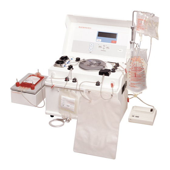
Introduction System Overview The ACP 215 device is an automated cell processor. The device has two pumps controlling the flow of fluids to the spinning centrifuge and the shaker. The device also has a thermal printer for the printing of reports at the end of the procedures. -
Page 14: Additional Support
Introduction Additional Support Many factors affect the performance of ACP 215 device, including the functional integrity of the instrument, the consistency of the disposable set, and the quality of the blood from the donor or freezer. When the device is properly calibrated and maintained, the instrument is very reliable and predictable and is designed to withstand substantial abuse. -
Page 15: Equipment Description
Air Detectors ..........37 ® ® Haemonetics ACP-215 Service Manual... -
Page 16: General
General The purpose of this chapter is to describe both the principles of operation and the internal and external components of the Haemonetics ACP 215 device. For detailed information on the use of the instrument and installation of the disposable, refer to your device’s Owner’s Operating and Maintenance Manual. -
Page 17: Specifications
Standard The device will meet the following standards: Requirements IEC 601-1, IEC 601-1-2, IEC 601-1-4 ASTM D5276 Drop test for loaded containers. ASTM D-999 Vibration testing for shipping containers. ® ® Haemonetics ACP-215 Service Manual P/N: SM-ACP215-01-EN(AB) -
Page 18: Environmental Conditions
The following symbols are found on the power switch located on the side of the device: Power OFF Power ON ® ® P/N: SM-ACP215-01-EN(AB) Haemonetics ACP-215 Service Manual... -
Page 19: Disposable Sets
Note: The bacteria barrier filter allows the attachment of the glycerol using a spike, while still maintaining a functionally closed system and allows the extension of the expiration date of the product. The filter does not restrict the flow of glycerol. ® ® Haemonetics ACP-215 Service Manual P/N: SM-ACP215-01-EN(AB) -
Page 20: Elements Of The Deglycerol-Ization Disposable Kit
Additive solution line: The orange-coded solution line contains a male luer connector to attach the selected additive solution bag to the disposable set. ® ® P/N: SM-ACP215-01-EN(AB) Haemonetics ACP-215 Service Manual... - Page 21 Product waste bag: This bag has a 5 liter capacity and collects the effluent that exits the bowl. This effluent is the waste of the different solutions used to wash the RBCs. ® ® Haemonetics ACP-215 Service Manual P/N: SM-ACP215-01-EN(AB)
-
Page 22: Biohazard Waste Bag
Two biohazard waste bags are supplied with the delivery of each ACP 215 device. A bag must be attached at all times to the centrifuge drain tube, located at the rear of the device. -
Page 23: Hardware Descriptions
Figure 4, ACP 215 top deck view Air Detectors The ACP 215 device is equipped with two ultrasonic sensors designed to detect the presence of air, bubbles or foam in the fluids flowing through the disposable set tubing. The solution line air detector (SLAD) is located to the right of the solution pump. -
Page 24: Pumps
During Prime, adding hypertonic solution, and dilution, the blood pump rotates counterclockwise (CCW) simultaneously with the solution pump to drive the solution to the RBC bag located on the shaker. See Figure 4 on page 23 Figure 5 on page ® ® P/N: SM-ACP215-01-EN(AB) Haemonetics ACP-215 Service Manual... - Page 25 ±2.25 A to the motor. To insure reliability, the heat sink temperature is measured and compared to a 90 degree Celsius threshold by U13 and U23. The CPU monitors the compare signal and can respond to an overheating condition. ® ® Haemonetics ACP-215 Service Manual P/N: SM-ACP215-01-EN(AB)
-
Page 26: Pinch Valves
Pinch Valves There are six pneumatic pinch valves located on the ACP 215 top deck which automatically control the flow of fluids through the disposable set tubing. These valves are color-coded to facilitate accurate tubing installation. -
Page 27: Centrifuge
+28 VDC signal. The +28 VDC is used by the centrifuge distribution card to energize a relay, which directly controls the +48 VDC centrifuge drive source. Both signals are then optically isolated and monitored on the CPU card through an I/O port. ® ® Haemonetics ACP-215 Service Manual P/N: SM-ACP215-01-EN(AB) -
Page 28: Fluid Detector
If the line sensor is found to be out of calibration, the device stops all activities and requests the user to contact Haemonetics for repair. -
Page 29: Shaker
(peak-to-peak). Note: The shaker unit is not repairable in the field. For technical assistance or to have your shaker serviced in the USA, call Haemonetics Customer Care Service at 1-800-537-2802. For technical assistance or to have your shaker serviced in other countries, please contact your local Haemonetics representative. -
Page 30: Printer
The device controls the printer but it has an independent power source via a wall unit adapter that converts 110 VAC or 230VAC into DC. ® ® P/N: SM-ACP215-01-EN(AB) Haemonetics ACP-215 Service Manual... -
Page 31: Card Cage
The valve drive and position feedback circuitry are identical to the drive PCB electronics. The add valve card communicates to the CPU through the backplane PCB and a ribbon cable between the backplane card and the add- valve PCB. ® ® Haemonetics ACP-215 Service Manual P/N: SM-ACP215-01-EN(AB) -
Page 32: Top Deck Distribution Board
The tachometer pulses (two per revolution) are optically isolated and fed to a counter on the drive board which can be read by the CPU. ® ® P/N: SM-ACP215-01-EN(AB) Haemonetics ACP-215 Service Manual... -
Page 33: Power Entry Module
200 - 240 Volts AC: 2.5 A, 250 V, Type F, 5 mm x 20 mm Input power receptacle: Allows the connection to the power cord. Electrical line filter: Reduces the effects of power surge on the device operation. ® ® Haemonetics ACP-215 Service Manual P/N: SM-ACP215-01-EN(AB) -
Page 34: Power Supply
All outputs are protected against overload and short circuit. Recovery is automatic when the fault is removed. The supply is cooled by a self-mounted fan; this improves the stability of the voltage levels. ® ® P/N: SM-ACP215-01-EN(AB) Haemonetics ACP-215 Service Manual... -
Page 35: Control Panel
The membrane panel is a key matrix membrane mounted to a printed circuit card. The matrix is electrically connected to the display distribution board. The vacuum display ® ® Haemonetics ACP-215 Service Manual P/N: SM-ACP215-01-EN(AB) -
Page 36: Dpm/Spm
Hall effect sensors detect the magnetic field of a magnet mounted on the sliding filter sleeve. When the sleeve is extended, the interlock signals measure +5 VDC. When the sleeve is depressed and the hall effect sensors detect the ® ® P/N: SM-ACP215-01-EN(AB) Haemonetics ACP-215 Service Manual... -
Page 37: Air Detectors
Two one-second timers will be started whenever air is present. If time-out occurs, the corresponding faults will be presented to the fault registers and the procedure will be aborted by opening the relays. ® ® Haemonetics ACP-215 Service Manual P/N: SM-ACP215-01-EN(AB) -
Page 39: Principles Of Operation
Protocol selection ......... .93 ® ® Haemonetics ACP-215 Service Manual... -
Page 40: General
Principles of Operation General The ACP 215 device operates in three modes: System Start-up Test mode Application mode Utilities mode The System Start-up Test mode is executed automatically when the device is powered on. It consists of hidden and displayed system tests that test the viability of the computer functions. -
Page 41: System Start-Up Tests
The test names are displayed in a group resembling a chart and are listed in the order they occur. The tests displayed in the left column are system and peripheral tests, and the tests displayed in the right ® ® Haemonetics ACP-215 Service Manual P/N: SM-ACP215-01-EN(AB) - Page 42 If the calibration variables have changed since the calibration values were set or if the CRC value stored in the NVRAM has changed, the computed CRC will not match the stored CRC, ® ® P/N: SM-ACP215-01-EN(AB) Haemonetics ACP-215 Service Manual...
- Page 43 (Protocol variables are user modifiable options that are protocol specific, and are accessed by using the MODIFY PROGRAM key during the Application mode.) The following error ® ® Haemonetics ACP-215 Service Manual P/N: SM-ACP215-01-EN(AB)
- Page 44 Only the donor pressure monitor (DPM) and system pressure monitor (SPM) channels are tested. Note: Both the A/D converter and the multiplexer are located on the CPU PCB. ® ® P/N: SM-ACP215-01-EN(AB) Haemonetics ACP-215 Service Manual...
- Page 45 If the filter is not removed within fifty seconds, the interlock will be presumed defective and the test will fail. DPM FILTER INTERLOCK FAILURE CODE = 507 PLEASE POWER OFF. DPM FILTER INTERLOCK FAILURE CODE = 507 PLEASE POWER OFF. ® ® Haemonetics ACP-215 Service Manual P/N: SM-ACP215-01-EN(AB)
- Page 46 DPM FAILED 20% ANALOG TEST CODE = 10 PLEASE POWER OFF. DPM FAILED 50% ANALOG TEST CODE = 10 PLEASE POWER OFF. DPM FAILED 80% ANALOG TEST CODE = 10 PLEASE POWER OFF. ® ® P/N: SM-ACP215-01-EN(AB) Haemonetics ACP-215 Service Manual...
- Page 47 One of the following error messages will be displayed: DPM OUT OF TOLERANCE CODE = 514 PLEASE POWER OFF. SPM OUT OF TOLERANCE CODE = 515 PLEASE POWER OFF. ® ® Haemonetics ACP-215 Service Manual P/N: SM-ACP215-01-EN(AB)
- Page 48 LINE SENSOR MAY HAVE A BLOCKAGE PLEASE REMOVE TUBING OR CLEAN LINE SENSOR PRESS YES TO CONTINUE. ® ® P/N: SM-ACP215-01-EN(AB) Haemonetics ACP-215 Service Manual...
- Page 49 The following error message will be displayed if switch position confirmation fails. RED VALVE POSITION FAULT CODE = 12 PLEASE POWER OFF. ® ® Haemonetics ACP-215 Service Manual P/N: SM-ACP215-01-EN(AB)
- Page 50 PLEASE POWER OFF. BLUE VALVE POSITION FAULT CODE = 12 PLEASE POWER OFF. YELLOW VALVE POSITION FAULT CODE = 12 PLEASE POWER OFF. ORANGE VALVE POSITION FAULT CODE = 12 PLEASE POWER OFF. ® ® P/N: SM-ACP215-01-EN(AB) Haemonetics ACP-215 Service Manual...
- Page 51 PLEASE POWER OFF. GREEN VALVE CURRENT FAULT CODE = 13 PLEASE POWER OFF. BLUE VALVE CURRENT FAULT CODE = 13 LEASE POWER OFF YELLOW VALVE CURRENT FAULT CODE = 13 PLEASE POWER OFF. ® ® Haemonetics ACP-215 Service Manual P/N: SM-ACP215-01-EN(AB)
-
Page 52: Centrifuge Cover Test
(cover locked or unlocked) to determine what message to display. The cover lock state must be switched three times to satisfy the test requirements. If the optical sensors fail to transition states, no error message ® ® P/N: SM-ACP215-01-EN(AB) Haemonetics ACP-215 Service Manual... - Page 53 Principles of Operation is generated. The test process simply will not continue. PLEASE OPEN CENTRIFUGE COVER PLEASE CLOSE CENTRIFUGE COVER then THANK YOU! The start-up system tests are now complete. ® ® Haemonetics ACP-215 Service Manual P/N: SM-ACP215-01-EN(AB)
-
Page 54: Utilities Mode
Machine market International International, North America Note: Once the market has been selected the default market values are set into the memory of the machine as displayed in the market tables below. ® ® P/N: SM-ACP215-01-EN(AB) Haemonetics ACP-215 Service Manual... - Page 55 The following flow chart detail the User interface within the protocol configuration of the ACP215. These are market dependent and will be available once the market configuration has been set under the machine configuration menu. Note: See configuration setup procedure in Chapter ® ® Haemonetics ACP-215 Service Manual P/N: SM-ACP215-01-EN(AB)
- Page 56 Large Bowl Without Both With Addi ve User Select 275 ml 325 ml Addi ve Store in Store in Store in Store in Store in Store in NVRAM NVRAM NVRAM NVRAM NVRAM NVRAM ® ® P/N: SM-ACP215-01-EN(AB) Haemonetics ACP-215 Service Manual...
- Page 57 Display De- NO OPTIONS NO OPTIONS Glyc. Op ons AVAILABLE AVAILABLE Bowl Size Op on Small Bowl Large Bowl Both 275 ml 325 ml Store in Store in Store in NVRAM NVRAM NVRAM ® ® Haemonetics ACP-215 Service Manual P/N: SM-ACP215-01-EN(AB)
-
Page 59: Preventive Maintenance And Installation
DPM and SPM Sensor Test........97 ® ® Haemonetics ACP-215 Service Manual... - Page 60 Service Report ..........102 ® ® P/N: SM-ACP215-01-EN(AB) Haemonetics ACP-215 Service Manual...
-
Page 61: General
Any time the device is disassembled to any extent beyond removing the access panels. Any time there is a fluid spill on the device or other potential physical damage that may have affected the integrity of the unit. ® ® Haemonetics ACP-215 Service Manual P/N: SM-ACP215-01-EN(AB) -
Page 62: Initial Inspection
Integrity doubt as to whether the service technician’s adjustments caused a problem should the device fail to operate properly after the preventive maintenance is complete. ® ® P/N: SM-ACP215-01-EN(AB) Haemonetics ACP-215 Service Manual... -
Page 63: Record The Program Revision Level
Record this revision level and ensure that the device is operating at the current revision level. In the U. S., direct inquires about the current revision level to the Haemonetics hotline at 1-800- 537-2802. Outside the U.S. contact the appropriate Haemonetics office. -
Page 64: System Cleaning
This list is not intended to be all inclusive. For cleaning agents that are not on the above list and you are not sure about, please call Haemonetics Corporation to determine if the cleaning agent is appropriate for use in daily maintenance. -
Page 65: Cleaning Overview
Cleaning agent’s material safety data sheet (MSDS) Cleaning As with any precision instrument, the ACP 215 device must be cleaned Overview periodically. The frequency and type of cleaning depends on the number of procedures performed with the device. -
Page 66: Pumps
Using disinfectant cleaner applied to a paper towel or soft cloth dampened with Panel water, clean any contamination from the membrane panel and display. Do not use spray cleaner directly on the front panel display. ® ® P/N: SM-ACP215-01-EN(AB) Haemonetics ACP-215 Service Manual... -
Page 67: Deck
If the sleeve is installed at angle, it is not installed correctly and should reinstalled. Outside of Clean any contamination from the outside of the cabinet using disinfectant Cabinet cleaner applied to a paper towel or soft cloth dampened with water. ® ® Haemonetics ACP-215 Service Manual P/N: SM-ACP215-01-EN(AB) -
Page 68: Equipment Integrity Inspection
There should be a clearance of at least 1/8” between the centrifuge and the deck cavity all the way around the centrifuge and a visible gap between the base of the centrifuge rim and the deck surface. ® ® P/N: SM-ACP215-01-EN(AB) Haemonetics ACP-215 Service Manual... -
Page 69: Consumables Replacement
The three air filters on the bottom of the device. The filter on the inlet of the compressor for the pneumatic valve system, part number 17400-00. (The compressor is mounted above the power supply.) ® ® Haemonetics ACP-215 Service Manual P/N: SM-ACP215-01-EN(AB) -
Page 70: Printer Installation
0 to the position marked l. Note: If doing a device installation, or CPU replacement, complete the configuration steps in Chapter 5, Calibration and Configuration. ® ® P/N: SM-ACP215-01-EN(AB) Haemonetics ACP-215 Service Manual... -
Page 71: Loading Paper
Note: The receptacle is located at the back of the device. It is positioned 3.5 inches from the bottom, left of center, above and to the right of the receptacle marked SHAKER. ® ® Haemonetics ACP-215 Service Manual P/N: SM-ACP215-01-EN(AB) - Page 72 Figure 17, AC adapter 5. Turn the printer on by moving the slider switch located on the left hand side of the printer from the position marked 0 to the position marked l. ® ® P/N: SM-ACP215-01-EN(AB) Haemonetics ACP-215 Service Manual...
-
Page 73: Printer Test
2. Press MODIFY PROGRAM until the arrow points to PRINT CALIB, then press START. 3. Press MODIFY PROGRAM until the arrow points to PRINT CALIB VALUES, then press START. 4. Verify that the printer prints out the calibration values. ® ® Haemonetics ACP-215 Service Manual P/N: SM-ACP215-01-EN(AB) -
Page 74: Diagnostic Testing
1. Turn the printer on by moving the slider switch located on the left-hand side of the printer from the position marked “0” to the position marked “l”. 2. Ensure that the green online LED illuminates. See Figure 19 on page ® ® P/N: SM-ACP215-01-EN(AB) Haemonetics ACP-215 Service Manual... -
Page 75: Functional/Pump/Shaker Check
6. Verify that the printer prints out the calibration values. Functional/ Functional Test Pump/Shaker 1. Power on the device. Check After completion of system tests and cover lock test, the screen displays: HAEMONETICS ACP 215 PLEASE SELECT PROTOCOL -> GLYCEROLIZATION DE-GLYCEROLIZATION ® ® Haemonetics... - Page 76 The device emits a beeping alert sound. 6. Attach the pressure monitor test harness to DPM. 7. Attach a Bio-Tek Model DPM-11 (or equivalent) pressure meter the pressure monitor test harness. and press YES to continue. The screen ® ® P/N: SM-ACP215-01-EN(AB) Haemonetics ACP-215 Service Manual...
- Page 77 YES to continue. the screen displays: CALIBRATION OF LINE SENSOR PRESS YES TO CALIBRATE PRESS NO TO BYPASS CALIBRATION PUMP TIME HYPE NACL ADDI REAL: TARG: 1470 The device continues beeping. ® ® Haemonetics ACP-215 Service Manual P/N: SM-ACP215-01-EN(AB)
- Page 78 PRESS YES OR NO TO CONTINUE PUMP TIME HYPE NACL ADDI REAL: TARG: 1470 The device continues beeping. Note: If the bowl makes noise replace it with a new bowl and close and lock the centrifuge cover. ® ® P/N: SM-ACP215-01-EN(AB) Haemonetics ACP-215 Service Manual...
- Page 79 BOWL SEATING TEST DID BOWL PRODUCE UNUSUAL NOISE PRESS YES OR NO TO CONTINUE PUMP TIME HYPE NACL ADDI REAL: TARG: 1470 The device continues beeping. ® ® Haemonetics ACP-215 Service Manual P/N: SM-ACP215-01-EN(AB)
- Page 80 BLUE Striped tubing connected to Hypertonic Solution bag. PUMP TIME HYPE NACL ADDI REAL: TARG: 1470 19.Press YES to continue. 20.Repeat for the wash solution, additive solution, and solution air detector screens. ® ® P/N: SM-ACP215-01-EN(AB) Haemonetics ACP-215 Service Manual...
- Page 81 Blood tubing Laced in Blood Air Detector. PUMP TIME HYPE NACL ADDI REAL: TARG: 1470 25.Ensure that the water-filled tubing is laced in the blood air detector and the light is on. ® ® Haemonetics ACP-215 Service Manual P/N: SM-ACP215-01-EN(AB)
- Page 82 NACL ADDI REAL: TARG: 1470 28.Press YES to continue. The screen displays: Check, Press YES To Continue Sterile connect RBC bag to RED Striped tubing. PUMP TIME HYPE NACL ADDI REAL: TARG: 1470 ® ® P/N: SM-ACP215-01-EN(AB) Haemonetics ACP-215 Service Manual...
- Page 83 1470 The first “A” blinks. 31.Press SAVE PROGRAM twice. The screen displays: OPERATOR INITIALS A A PRESS YES to CONTINUE PRESS NO to RE-ENTER PUMP TIME HYPE NACL ADDI REAL: TARG: 1470 ® ® Haemonetics ACP-215 Service Manual P/N: SM-ACP215-01-EN(AB)
- Page 84 RPM. 3. Measure the speed of the BLOOD pump and verify the reading is 100 +/- 2 rpm. ® ® P/N: SM-ACP215-01-EN(AB) Haemonetics ACP-215 Service Manual...
- Page 85 The BLOOD pump SOLUTION pump and the SHAKER will start. 7. Quickly measure the speed of the Blood and the Solution Pumps. They will be running at 150 +/- 2 RPM. Record these values. ® ® Haemonetics ACP-215 Service Manual P/N: SM-ACP215-01-EN(AB)
- Page 86 1. Unplug the shaker. After a time the screen displays: DE-GLYCEROLIZATION PROTOCOL Check Shaker Connection Press YES to continue PUMP TIME HYPE NACL ADDI REAL: TARG: 1470 The device emits a beeping alert sound. ® ® P/N: SM-ACP215-01-EN(AB) Haemonetics ACP-215 Service Manual...
-
Page 87: Rotor Durometer Test
6. Use a Meylan, Model 109 Digital Tachometer (or equivalent) to measure the operating speed (RPM). Verify that it is 180 +/- 2 RPM. Rotor Note: This test is performed during the annual preventive maintenance by Durometer Haemonetics personnel only. Test Procedure - Method 1 Materials Required Hexagonal head wrench ... - Page 88 Figure 21, Note: Ensure the pump rotor and the fixture are engaged by introducing the fixture’s stud into the slit of the rotor. By design, one of the rotor rollers will be ® ® P/N: SM-ACP215-01-EN(AB) Haemonetics ACP-215 Service Manual...
- Page 89 Preventive Maintenance and Installation exposed at the fixture opening. Figure 22, 2. Gently grip the gauge with the opposite hand. Note: Reset the gauge before taking each measurement by pressing the reset button. Figure 23, ® ® Haemonetics ACP-215 Service Manual P/N: SM-ACP215-01-EN(AB)
- Page 90 Note: Inspect for deformity on the roller surface. If deformity is found then replace the rotor or roller. 6. Rotate the rotor 180 degrees and repeat the procedure with the second roller. ® ® P/N: SM-ACP215-01-EN(AB) Haemonetics ACP-215 Service Manual...
-
Page 91: Maintenance
Continue rocking until the indenter is no longer in contact with the foot. The contact time of the tool to the roller will be about 1-2 full ® ® Haemonetics ACP-215 Service Manual P/N: SM-ACP215-01-EN(AB) - Page 92 Replace rotor assembly or the roller if either of the average measurements fall outside of the specification for durometer or if the roller is sticky. The specification is 63 to 75 Shore A Durometer. ® ® P/N: SM-ACP215-01-EN(AB) Haemonetics ACP-215 Service Manual...
-
Page 93: Valves Test
5. Pressurize the sphygmomanometer, or digital pressure meter, to 200 mmHg and verify that there is not a leak as evidenced by a decrease in pressure. Press PUMP UP ARROW and remove the tubing. ® ® Haemonetics ACP-215 Service Manual P/N: SM-ACP215-01-EN(AB) - Page 94 3. Verify that valve 3 opens and its LED is lit. 4. Press PUMP DOWN ARROW and the valve closes. 5. Verify that valve 3 closes and its LED is not lit. ® ® P/N: SM-ACP215-01-EN(AB) Haemonetics ACP-215 Service Manual...
- Page 95 200 mmHg and verify that there is not a leak as evidenced by a decrease in pressure. Press HIDDEN KEY #3 and remove the tubing. 7. Press HIDDEN KEY #3 and the valve closes. ® ® Haemonetics ACP-215 Service Manual P/N: SM-ACP215-01-EN(AB)
- Page 96 Isolate problem to power (Eng./De-eng.), position switch (Open/ Closed), or valve current (High-current). See Chapter 7. Haemonetics does not recommend adjusting the valve position switch. 5. Exit the valves test by pressing MODIFY PROGRAM. Pneumatic Pinch Valve Pressure Test Note: Power on the device in the Utilities mode of operation by pressing and holding SHAKER while switching the power on.
-
Page 97: Dpm And Spm Sensor Test
Connect a calibrated electronic/digital measuring device or equivalent device to the filter tubing. Pressurize the DPM to 100mmHg +/- 5mmHg and verify that the displayed pressure reading is within the range of 95–105 mmHg. ® ® Haemonetics ACP-215 Service Manual P/N: SM-ACP215-01-EN(AB) -
Page 98: Display
8. Install a new DPM/SPM filter with about 4” of tubing onto the SPM. Connect a calibrated electronic/digital measuring device or equivalent device to the filter tubing. Pressurize the SPM to 100mmHg +/- 5mmHg and verify that the displayed pressure reading is within the range of 95– 105 mmHg. -
Page 99: Fluid Sensor Test
Note: Power on the device in the Utilities mode of operation by pressing and Test holding SHAKER while switching the power on. Hold SHAKER until the UTILITIES menu appears on the display. On the UTILITIES menu, press ® ® Haemonetics ACP-215 Service Manual P/N: SM-ACP215-01-EN(AB) -
Page 100: Line Sensor Test
5. Exit the Air Detector test by pressing MODIFY PROGRAM. Leakage 1. Plug the PCS2 into the leakage tester (Dale Technologies LT544D Lite Current or equivalent). 2. Plug the leakage tester into a grounded electrical outlet. ® ® P/N: SM-ACP215-01-EN(AB) Haemonetics ACP-215 Service Manual... -
Page 101: Ground Continuity
3. Attach the clip to the following exposed metal locations. Verify that there is continuity. Rear panel hardware Front panel hardware Pinch valve plungers 4. Verify the highest reading is less than 0.3 Ohm. ® ® Haemonetics ACP-215 Service Manual P/N: SM-ACP215-01-EN(AB) -
Page 102: Service Report
Preventive Maintenance and Installation Service Report The following page contains a blank sample service report for the ACP 215 device. ® ® P/N: SM-ACP215-01-EN(AB) Haemonetics ACP-215 Service Manual... - Page 103 Preventive Maintenance and Installation ® ® Haemonetics ACP-215 Service Manual P/N: SM-ACP215-01-EN(AB)
- Page 104 Preventive Maintenance and Installation ® ® P/N: SM-ACP215-01-EN(AB) Haemonetics ACP-215 Service Manual...
-
Page 105: Calibration And Configuration
Clock and Date Setting ........125 ® ® Haemonetics ACP-215 Service Manual... -
Page 106: Calibration Procedures
12.Check to ensure that the value is within tolerance and readjust if necessary. 13.Press PUMP UP ARROW to release the pneumatic pressure. 14.Remove the pressure meter and reconnect the red tubing. 15.Proceed to pinch valve occlusion test. ® ® P/N: SM-ACP215-01-EN(AB) Haemonetics ACP-215 Service Manual... -
Page 107: Line Sensor Signal
(the left-most card cage board, looking from the rear of the unit) to the Protect Off mode (down). The calibration screen appears with two choices: A/D and CENTRIFUGE. 5. Press MODIFY PROGRAM to move the arrow to A/D. 6. Press START. ® ® Haemonetics ACP-215 Service Manual P/N: SM-ACP215-01-EN(AB) - Page 108 Figure 29 on page 94 for the locations of hidden keys). This stores the SPM full scale value. 5. Record the full scale value. Remove the pressure meter and test harness. 6. Press the STOP key. ® ® P/N: SM-ACP215-01-EN(AB) Haemonetics ACP-215 Service Manual...
- Page 109 13.Press SAVE PROGRAM, which stores the value. 14.Press STOP. 15.Press MODIFY PROGRAM. 16.Press STOP. 17.The message REPLACE MEMORY PROTECTION appears. 18.Switch the memory protect switch on the CPU board to the Protect On mode (up). ® ® Haemonetics ACP-215 Service Manual P/N: SM-ACP215-01-EN(AB)
-
Page 110: Market Configuration Procedure - International/North America
Protect Off mode (down). The device displays: CONFIGURATION PROTOCOLS CONFIGURATION LANGUAGE —> MACHINE 4. Press MODIFY PROGRAM until MACHINE is selected and press START. The device displays: MACHINE CONFIGURATION SERIAL # RS232 DEVICE DATA LOGGING —> MARKET ® ® P/N: SM-ACP215-01-EN(AB) Haemonetics ACP-215 Service Manual... - Page 111 Protect On mode (up). The device displays: UTILITIES CALIBRATION DIAGNOSTICS —> CONFIGURATION MAINTENANCE AUTO-CYCLE TEST Note: The market configuration must be set prior to entering the protocol configuration (see Configuration Parameter Default Settings tables) ® ® Haemonetics ACP-215 Service Manual P/N: SM-ACP215-01-EN(AB)
- Page 112 Glycerolization De-Glycerolization 12.Press START. The screen displays: CELL WASH CONFIGURATION International -> Additive Figure 32, Additive option in cell wash Note: This option is not available in the North American market configuration. ® ® P/N: SM-ACP215-01-EN(AB) Haemonetics ACP-215 Service Manual...
- Page 113 Glycerolization protocol option parameter. 17.Press START. The screen displays: GLYCEROLIZATION CONFIGURATION International NO OPTIONS AVAILABLE PRESS STOP TO CONTINUE Figure 33, Glycerolization options 18.Press STOP. The International Market Protocol Configuration screen is displayed: ® ® Haemonetics ACP-215 Service Manual P/N: SM-ACP215-01-EN(AB)
- Page 114 23.Press MODIFY PROGRAM to change the of the Bowl Size setting within the deglycerolization protocol if necessary, then press START to confirm. 24.Press STOP five times to return to the Main Configuration screen. CONFIGURATION -> PROTOCOLS CONFIGURATION LANGUAGE MACHINE ® ® P/N: SM-ACP215-01-EN(AB) Haemonetics ACP-215 Service Manual...
- Page 115 Only (275ml) Only (275ml) *Sterile Check in Cell Wash Enabled *Sterile Check in Cell Wash Disabled Note: These parameters are market dependent and are only changed if the “Machine Market” configuration is changed. ® ® Haemonetics ACP-215 Service Manual P/N: SM-ACP215-01-EN(AB)
- Page 116 Large Bowl Without Both With Addi ve User Select 275 ml 325 ml Addi ve Store in Store in Store in Store in Store in Store in NVRAM NVRAM NVRAM NVRAM NVRAM NVRAM ® ® P/N: SM-ACP215-01-EN(AB) Haemonetics ACP-215 Service Manual...
- Page 117 Display De- NO OPTIONS NO OPTIONS Glyc. Op ons AVAILABLE AVAILABLE Bowl Size Op on Small Bowl Large Bowl Both 275 ml 325 ml Store in Store in Store in NVRAM NVRAM NVRAM ® ® Haemonetics ACP-215 Service Manual P/N: SM-ACP215-01-EN(AB)
-
Page 118: Language
—> ENGLISH ITALIAN FRENCH DUTCH GERMAN Language = ENGLISH 8. Press the STOP key two times to exit. The following message appears: CONFIGURATION PROTOCOLS CONFIGURATION —> LANGUAGE ****************************** REPLACE MEMORY** PROTECTION** ****************************** ® ® P/N: SM-ACP215-01-EN(AB) Haemonetics ACP-215 Service Manual... -
Page 119: Machine
—> Serial RS232 Device Data Logging 6. Press MODIFY PROGRAM until the arrow points to Serial # and then press START. The following is displayed: MACHINE SERIAL # MACHINE SERIAL # XXXXXX ® ® Haemonetics ACP-215 Service Manual P/N: SM-ACP215-01-EN(AB) - Page 120 (the left-most card cage board, looking from the rear of the unit) to the Protect Off mode (down). The CALIBRATION screen appears with three choices: PROTOCOLS CONFIGURATION, LANGUAGE, and MACHINE. 5. Press MODIFY PROGRAM to move the arrow to MACHINE, then press START. ® ® P/N: SM-ACP215-01-EN(AB) Haemonetics ACP-215 Service Manual...
-
Page 121: Device
MAINTENANCE 10.Press STOP and the device restarts and performs the self test. Device Data Logging Note: Data logging, recording of procedures, is not an active option on the device at this time. ® ® Haemonetics ACP-215 Service Manual P/N: SM-ACP215-01-EN(AB) - Page 122 START. The following screen is displayed: Data Logging ENABLE —> DISABLE Status = XXXXX 8. Press STOP three times. The following screen is displayed: CONFIGURATION PROTOCOLS CONFIGURATION —> LANGUAGE ****************************** REPLACE MEMORY** PROTECTION** ****************************** ® ® P/N: SM-ACP215-01-EN(AB) Haemonetics ACP-215 Service Manual...
- Page 123 9. Switch the memory protect switch on the CPU board to the Protect On mode (up) and the following display appears: UTILITIES CALIBRATION DIAGNOSTICS —> CONFIGURATION MAINTENANCE 10.Press STOP and the device restarts and performs the self test. ® ® Haemonetics ACP-215 Service Manual P/N: SM-ACP215-01-EN(AB)
-
Page 124: Maintenance Procedures
4. Press START and the following display appears: EXECUTED PROCEDURES #Executed Procedures XXXX PRESS START AGAIN TO RESET TO 0 OR PRESS STOP TO EXIT 5. Press START and the following display appears: EXECUTED PROCEDURES #Executed Procedures 0 ® ® P/N: SM-ACP215-01-EN(AB) Haemonetics ACP-215 Service Manual... -
Page 125: Clock And Date Setting
Note: To verify that calibration procedure values were stored correctly, proceed to DIAGNOSTICS in the UTLITIES menu. Perform all the tests listed in the diagnostics section and record all values before using the device. For more information, see “Diagnostic Testing” on page ® ® Haemonetics ACP-215 Service Manual P/N: SM-ACP215-01-EN(AB) -
Page 127: Disassembly
Fluid Detector Assembly ........144 ® ® Haemonetics ACP-215 Service Manual... - Page 128 Shaker ..........149 ® ® P/N: SM-ACP215-01-EN(AB) Haemonetics ACP-215 Service Manual...
-
Page 129: General
Whenever possible, AC power should be disconnected from the device before opening the cabinet. Static The ACP 215 device uses static-sensitive electronics. Serious damage may Discharge occur to the unit’s electronic systems if static discharge is not controlled. Internal components should only be handled after proper precautions have been taken to prevent static discharge. -
Page 130: Rear Panel Assembly
3. If removing less than all four fans, cut the wires so that they can be reconnected by using crimp style connectors. Cover Stops 1. Remove the rear panel. 2. Remove (2) Phillips head screws for each cover stop to be removed. ® ® P/N: SM-ACP215-01-EN(AB) Haemonetics ACP-215 Service Manual... -
Page 131: Front Panel Assembly
(3) Phillips head screws from the bottom edge of the front panel. Note: The ACP 215 device weighs approximately 56 lbs. Use extreme caution whenever tilting or moving the device to avoid dropping the device and causing damage to the device and to prevent injury to the operator or technician. -
Page 132: Card Cage Assembly
The CPU PCB is located in the first slot on the left, facing the rear of the device. 1. Remove the rear panel. 2. Unclasp the PCB levers and unplug the processor PCB from the backplane PCB. 3. Slide the PCB out of the card cage. ® ® P/N: SM-ACP215-01-EN(AB) Haemonetics ACP-215 Service Manual... -
Page 133: Main Program Assembly
3. Move the frame toward the rear of the cabinet, and rotate the base of the backplane PCB out the front cavity of the cabinet. 4. Slide the frame out the back cavity of the cabinet. ® ® Haemonetics ACP-215 Service Manual P/N: SM-ACP215-01-EN(AB) -
Page 134: Top Deck Assembly
2. If both top deck air detectors are removed, be sure to return them to the correct locations. The plugs are keyed, so use the descriptions on the top deck distribution PCB for identification. ® ® P/N: SM-ACP215-01-EN(AB) Haemonetics ACP-215 Service Manual... -
Page 135: Line Sensor
3. Slide the pinch valve into the gasket and mount into place. 4. Wipe excess grease from the pinch valve. 5. Be sure to install the electrical connector in the proper location on the top deck distribution PCB. ® ® Haemonetics ACP-215 Service Manual P/N: SM-ACP215-01-EN(AB) -
Page 136: Air Tank
3. Install the #10 hex screw to the center of the rotor and tighten until snug. DO NOT overtighten this screw. ® ® P/N: SM-ACP215-01-EN(AB) Haemonetics ACP-215 Service Manual... -
Page 137: Pump Rotor
3. The rotor should easily slip onto and off of the pump shaft. If not, determine if rotor or pump motor shaft is at fault and replace as necessary. ® ® Haemonetics ACP-215 Service Manual P/N: SM-ACP215-01-EN(AB) - Page 138 Dowel pin is perpendicular to the dowel pin hole and does not bind as you push into the rotor. If you have any binding, remove the dowel pin and inspect for damage. Ensure the correct part number dowel pin is being used. ® ® P/N: SM-ACP215-01-EN(AB) Haemonetics ACP-215 Service Manual...
- Page 139 Figure 35, Pump Rotor 7. Carefully push in the dowel pin until it comes to stop, then use the 7/32 pin punch and hammer to tap into place, through the following: a. Rotor Base ® ® Haemonetics ACP-215 Service Manual P/N: SM-ACP215-01-EN(AB)
-
Page 140: Spm/Dpm Detector Assembly
Note: With a thin wall socket and a bit of experience, you may be able to Detector remove these detectors without removing the top deck. Otherwise, see “Top Assembly Deck” on page 134 ® ® P/N: SM-ACP215-01-EN(AB) Haemonetics ACP-215 Service Manual... - Page 141 PCB to the SPM/DPM detector assembly. 6. Gently twist and pull the SPM/DPM detector PCB from the SPM/DPM pressure fitting. 7. We do not advise further disassembly of the SPM/DPM detector assembly. ® ® Haemonetics ACP-215 Service Manual P/N: SM-ACP215-01-EN(AB)
-
Page 142: Centrifuge Assembly
7. Install the centrifuge on the centrifuge mount, leaving the four mounting screws loose. 8. Adjust the centrifuge location, then tighten all eight screws and recheck the location of centrifuge. 9. Replace the waste bag mounting tray. ® ® P/N: SM-ACP215-01-EN(AB) Haemonetics ACP-215 Service Manual... -
Page 143: Cover Switch
Be sure that no Loctite has spread to the threads above the centrifuge shaft spacer and that no Loctite is touching the centrifuge cap assembly where the shaft and the spacer come into contact with the centrifuge cap assembly. ® ® Haemonetics ACP-215 Service Manual P/N: SM-ACP215-01-EN(AB) -
Page 144: Fluid Detector Assembly
1. Disconnect the connector from the centrifuge distribution board. Assembly 2. Remove the (1) center Phillips head screw from the fluid detector assembly pcb. 3. Gently twist the fluid detector assembly out of the centrifuge well. ® ® P/N: SM-ACP215-01-EN(AB) Haemonetics ACP-215 Service Manual... -
Page 145: Top Cover Assembly
4. Carefully pry the display distribution PCB up to disconnect it from the membrane panel at the connector. Note: If the display distribution PCB was elevated by nylon washers, be sure to replace them before installing the display distribution PCB. ® ® Haemonetics ACP-215 Service Manual P/N: SM-ACP215-01-EN(AB) -
Page 146: Vacuum Display
Note: If the vacuum display was elevated by nylon washers, be sure to replace them before installing the vacuum display. Note: When replacing the vacuum display, call the Haemonetics Hotline and verify the correct parts to order. Depending on the present display configuration, it may be necessary to add a shim between the vacuum display and the membrane panel. -
Page 147: Power Entry Module
3. Replace with same size and rating fuse (5A 250V for 120VAC devices and 2.5A 250V for 240VAC devices). Note: When replacing fuse holders, be sure the arrows on the fuse holder and power entry module face the same direction. ® ® Haemonetics ACP-215 Service Manual P/N: SM-ACP215-01-EN(AB) -
Page 148: Power Supply Assembly
1. Remove the front panel. Motor 2. Disconnect the connectors from the centrifuge motor controller PCB. Controller PCB 3. Remove the (4) Phillips head screws securing the centrifuge motor controller PCB to the power supply cage. ® ® P/N: SM-ACP215-01-EN(AB) Haemonetics ACP-215 Service Manual... -
Page 149: Drain Tube Assembly
The shaker unit is not repairable in the field. For technical assistance, or to have your shaker serviced in the USA, call Haemonetics Customer Care Center at 1-800-537-2802. For technical assistance, or to have your shaker serviced in other countries, please contact your local Haemonetics representative. -
Page 151: Troubleshooting
CPU Error Messages........154 ® ® Haemonetics ACP-215 Service Manual... -
Page 152: General
Operation". Note: The shaker unit is not repairable in the field. For technical assistance, or to have your shaker serviced in the USA, call Haemonetics Customer Care Service at 1-800-537-2802. For technical assistance or to have your shaker serviced in other countries, please contact your local Haemonetics representative. -
Page 153: Status Messages
This chapter lists status messages that could be displayed if a hardware failure occurs, although such messages do not usually indicate a hardware failure. These status messages are listed along with the CPU generated error messages. ® ® Haemonetics ACP-215 Service Manual P/N: SM-ACP215-01-EN(AB) -
Page 154: Error Messages
Replace CPU PCB. Using Utilities, ERROR are not operating calibrate all components under A/D, and correctly. CENTRIFUGE, and configure the language. Reset protocol parameters (MODIFY PROGRAM) if parameters were different from the default values. ® ® P/N: SM-ACP215-01-EN(AB) Haemonetics ACP-215 Service Manual... - Page 155 ANALOG TEST converter failed 20% calibrate all components under A/D, and analog voltage load test. CENTRIFUGE, and configure the language. Reset protocol parameters (MODIFY PROGRAM) if parameters were different from the default values. ® ® Haemonetics ACP-215 Service Manual P/N: SM-ACP215-01-EN(AB)
- Page 156 ANALOG TEST converter failed 80% calibrate all components under A/D, and analog voltage load test. CENTRIFUGE, and configure the language. Reset protocol parameters (MODIFY PROGRAM) if parameters were different from the default values. ® ® P/N: SM-ACP215-01-EN(AB) Haemonetics ACP-215 Service Manual...
- Page 157 9. Replace driver or CPU PCB. Using Utilities, calibrate all components under A/D, and centrifuge, and configure the language. Reset protocol parameters (MODIFY PROGRAM) if parameters were different from default values. ® ® Haemonetics ACP-215 Service Manual P/N: SM-ACP215-01-EN(AB)
- Page 158 9. Replace driver or CPU PCB. Using Utilities, calibrate all components under A/D, and centrifuge, and configure the language. Reset protocol parameters (MODIFY PROGRAM) if parameters were different from default values. ® ® P/N: SM-ACP215-01-EN(AB) Haemonetics ACP-215 Service Manual...
- Page 159 9. Replace driver or CPU PCB. Using Utilities, calibrate all components under A/D, and centrifuge, and configure the language. Reset protocol parameters (MODIFY PROGRAM) if parameters were different from default values. ® ® Haemonetics ACP-215 Service Manual P/N: SM-ACP215-01-EN(AB)
- Page 160 9. Replace driver or CPU PCB. Using Utilities, calibrate all components under A/D, and centrifuge, and configure the language. Reset protocol parameters (MODIFY PROGRAM) if parameters were different from default values. ® ® P/N: SM-ACP215-01-EN(AB) Haemonetics ACP-215 Service Manual...
- Page 161 9. Replace driver or CPU PCB. Using Utilities, calibrate all components under A/D, and centrifuge, and configure the language. Reset protocol parameters (MODIFY PROGRAM) if parameters were different from default values. ® ® Haemonetics ACP-215 Service Manual P/N: SM-ACP215-01-EN(AB)
- Page 162 9. Replace driver PCB or CPU PCB. Using Utilities, calibrate all components under A/D, and centrifuge, and configure the language. Reset protocol parameters (MODIFY PROGRAM) if parameters were different from default values. ® ® P/N: SM-ACP215-01-EN(AB) Haemonetics ACP-215 Service Manual...
- Page 163 4. If not, replace driver PCB. 5. Replace CPU PCB. Using Utilities, calibrate all components under A/D, and centrifuge, and configure the language. Reset protocol parameters (MODIFY PROGRAM) if parameters were different from default values. ® ® Haemonetics ACP-215 Service Manual P/N: SM-ACP215-01-EN(AB)
- Page 164 4. If not, replace driver PCB. 5. Replace CPU PCB. Using Utilities, calibrate all components under A/D, and centrifuge, and configure the language. Reset protocol parameters (MODIFY PROGRAM) if parameters were different from default values. ® ® P/N: SM-ACP215-01-EN(AB) Haemonetics ACP-215 Service Manual...
- Page 165 4. If not, replace ADD valve PCB. 5. Replace CPU PCB. Using Utilities, calibrate all components under A/D, and centrifuge, and configure the language. Reset protocol parameters (MODIFY PROGRAM) if parameters were different from default values. ® ® Haemonetics ACP-215 Service Manual P/N: SM-ACP215-01-EN(AB)
- Page 166 A/D, and during system start-up centrifuge, and configure the language. watchdog test. Reset protocol parameters (MODIFY PROGRAM) if parameters were different from default values. ® ® P/N: SM-ACP215-01-EN(AB) Haemonetics ACP-215 Service Manual...
- Page 167 4. If digital values differ significantly, replace CPU PCB. Using Utilities, calibrate all components under A/D, and centrifuge, and configure the language. Reset protocol parameters (MODIFY PROGRAM) if parameters were different from default values. ® ® Haemonetics ACP-215 Service Manual P/N: SM-ACP215-01-EN(AB)
- Page 168 Use Utilities to re-calibrate A/D. 3. Replace CPU PCB. Using Utilities, calibrate all components under A/D, and centrifuge, and configure the language. Reset protocol parameters (MODIFY PROGRAM) if parameters were different from default values. ® ® P/N: SM-ACP215-01-EN(AB) Haemonetics ACP-215 Service Manual...
- Page 169 Use Utilities to re-calibrate A/D. 3. Replace CPU PCB. Using Utilities, calibrate all components under A/D, and centrifuge, and configure the language. Reset protocol parameters (MODIFY PROGRAM) if parameters were different from default values. ® ® Haemonetics ACP-215 Service Manual P/N: SM-ACP215-01-EN(AB)
- Page 170 3. Replace BLAD air detector. 4. Replace CPU PCB. Using Utilities, calibrate all components under A/D, and centrifuge, and configure the language. Reset protocol parameters (MODIFY PROGRAM) if parameters were different from default values. ® ® P/N: SM-ACP215-01-EN(AB) Haemonetics ACP-215 Service Manual...
- Page 171 2. Replace CPU PCB. Using Utilities, calibrate all components under A/D, and centrifuge, and configure the language. Reset protocol parameters (MODIFY PROGRAM) if parameters were different from default values. ® ® Haemonetics ACP-215 Service Manual P/N: SM-ACP215-01-EN(AB)
- Page 172 FAILURE test. 2. Replace CPU PCB. Using Utilities, calibrate all components under A/D, and centrifuge, and configure the language. Reset protocol parameters (MODIFY PROGRAM) if parameters were different from default values. ® ® P/N: SM-ACP215-01-EN(AB) Haemonetics ACP-215 Service Manual...
-
Page 173: Repair Parts List
Parts List...........176 ® ® Haemonetics ACP-215 Service Manual... -
Page 174: General
Repair Parts List General This chapter lists repair parts available for the ACP 215 device. For technical assistance or to schedule service in the USA, call Haemonetics Customer Care Center at 1-800-537-2802. For technical assistance, or to schedule service in other countries, please contact your local Haemonetics representative. -
Page 175: Rohs Parts
RoHS compliant machines will have a G at the end of the machine serial RoHS number. Compliant Caution: When repairing machines please ensure that only RoHS parts are Devices used in RoHS machines in order to stay RoHS compliant. ® ® Haemonetics ACP-215 Service Manual P/N: SM-ACP215-01-EN(AB) -
Page 176: Parts List
06 -Spanish, 07 -Portuguese, 08 -Dutch, 09 -Swedish,10 -Danish, 11-Finnish, 12 -Norwegian, 13 -Greek Display power cable assembly (3 pin) 50443-00 Display vacuum fluorescent 110460-00 Display sig cable assembly (20 pin) 35232-00 ® ® P/N: SM-ACP215-01-EN(AB) Haemonetics ACP-215 Service Manual... - Page 177 Pinch valve assembly (02K085 and newer) 37136-00 Pinch Valve Extension cable (02K085 and 51342-00 newer) Bl/AC/xfer pump assembly 37607-00 Pump rotor assembly 37606-00 Motor assembly 35367-00 Line sensor assembly 73048-10 48073-00 Line sensor gasket 48074-00 ® ® Haemonetics ACP-215 Service Manual P/N: SM-ACP215-01-EN(AB)
- Page 178 Parts description Non-RoHS Returnable Part No. DPM sensor assembly 79403-10 37049-00 DPM sensor PCB assembly 36965-10 36965-00 Rear panel assembly 48064-00 EMC gasket (UOM ft - 2 ft per panel 102246-02 needed) Fan assembly 35830-00 CPU To serial port cable assembly 49984-00 European caution label 50966-XX...
- Page 179 48221-00 Mother (backplane) PCB assembly 36443-10 36443-02 Main program assembly 49900-00 CPU PCB assembly 39208-12 39208-02 Centrifuge dist. PCB assembly 35215-10 35215-00 Rework driver PCB assembly 50050-00 Driver PCB assembly 36557-12 36557-04 ® ® Haemonetics ACP-215 Service Manual P/N: SM-ACP215-01-EN(AB)
- Page 180 Cable Assembly Shaker Bulkhead 48194-00 Cable Assembly Unit To Shaker 48195-00 Thermal Printer 50063-01 Printer Power Supply 110 Vac 50064-00 Printer Power Supply 220 Vac 50065-00 Printer PaperQ 50222-00 Printer Data Cable 49982-00 ® ® P/N: SM-ACP215-01-EN(AB) Haemonetics ACP-215 Service Manual...
-
Page 181: System Schematics
Line Sensor Fixture Schematic........185 ® ® Haemonetics ACP-215 Service Manual... -
Page 182: System Schematic
System Schematics System Schematic P/N: SM-ACP215-01-EN(AB) Haemonetics ® ACP-215 ® Service Manual... -
Page 183: Family Tree
System Schematics Family Tree Haemonetics ® ACP-215 ® Service Manual P/N: SM-ACP215-01-EN(AB) -
Page 184: Pneumatic Schematic
System Schematics Pneumatic Schematic P/N: SM-ACP215-01-EN(AB) Haemonetics ® ACP-215 ® Service Manual... -
Page 185: Line Sensor Fixture Schematic
System Schematics Line Sensor Fixture Schematic Table 10 Connector Wire reference Wire Color Number (Wx) Pin 4 Green Pin 5 Black Pin 8 ® ® Haemonetics ACP-215 Service Manual P/N: SM-ACP215-01-EN(AB)
Need help?
Do you have a question about the ACP 215 and is the answer not in the manual?
Questions and answers