Table of Contents
Advertisement
Quick Links
Advertisement
Table of Contents

Related Manuals for Haemonetics PCS2


Summary of Contents for Haemonetics PCS2
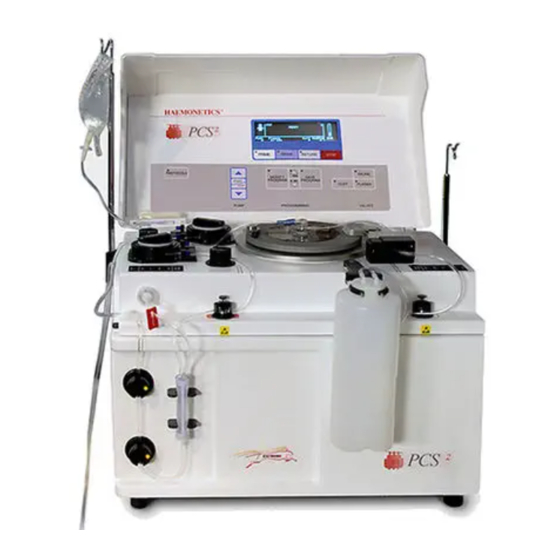
- Page 1 HAEMONETICS ® ® S e r v i c e a n d M a i n t e n a n c e M a n u a l...
- Page 2 HAEMONETICS ® ® Service and Maintenance Manual HAEMONETICS CORPORATION Part Number 38855-00 400 Wood Road, Braintree, MA 02184 Rev. D, June 2003...
- Page 3 PROPRIETARY MATERIAL Information and descriptions contained herein are the property of Haemonetics Corporation. Except where indicated, such information and descriptions may not be copied or reproduced by any means, or disseminated or distributed without the express prior written permission of Haemonetics Corporation.
-
Page 4: Table Of Contents
Table of Contents Chapter 1, Introduction General............................1-1 Additional Support ........................1-2 Chapter 2, Machine Part Replacement Reference Cautions ............................2-1 Static Discharge ..........................2-1 Notes.............................2-1 Rear Panel.............................2-2 Fan Assembly .........................2-2 Cover Stops..........................2-2 Cuff Connector ........................2-2 Front Panel............................2-2 Donor Line Air Detectors 1 and 2 ..................2-3 Compressor..........................2-3 Front Panel Distribution Board....................2-4 Card Cage .............................2-4... - Page 5 AC and Saline Pole Holder Assembly..................2-24 Drain Tube Assembly .........................2-24 Photoelectric Assembly ......................2-24 Line Conditioner.........................2-25 Table 2-1, PCS2 Component Calibration and Diagnostic Matrix ..........2-26 Chapter 3, Basic Care and Preventive Maintenance Initial Inspection ...........................3-1 Visual Inspection ........................3-1 Ensure Initial Operational Integrity ..................3-2 Record the Program Revision Level..................3-2...
- Page 6 Centrifuge Speed and Bowl Vibration Test ................3-7 Donor Lights Test ........................3-7 Line Sensor Test ........................3-8 Bowl Optics Signal Test ......................3-8 Air Detector Test ........................3-10 PCS2 Functional Test ......................3-10 Safety Testing ..........................3-12 Leakage Current ........................3-12 Ground Continuity........................3-12 Chapter 4, Calibration Calibration Procedures .........................4-1 Power Supply Voltages ......................4-1...
- Page 7 Donor Lights Test ........................5-9 Line Sensor Test ........................5-9 Bowl Optics Signal Test ......................5-9 Air Detector Test ........................5-11 PCS2 Functional Test ......................5-11 Leakage Current ........................5-13 Ground Continuity........................5-13 Machine Transfers ........................5-14 Source Plasma Customers Only ...................5-14 PCS2 Machine Transfer Verfication Form ................5-15...
- Page 8 PCS2 Exploded View with Callouts .....................7-3 PCS2 Centrifuge Exploded Views with Callouts .................7-4 PCS2 Card Cage and Air Filters Exploded Views with Callouts ..........7-5 PCS2 Power Supply Assembly Exploded Views with Callouts ...........7-6 PCS2 Pump Assembly Exploded View with Callouts..............7-7 Parts List by Assembly .........................7-8...
- Page 9 PCS2 Service Manual Chapter 8, Cleaning and Maintenance, cont. Air Filters..........................8-9 Internal Chassis.........................8-9 Leakage Current Check ......................8-10 Return Goods Authorization (RGA)...................8-11 RGA Procedure........................8-11 Haemonetics Quality Program....................8-12 Chapter 9, Technical Bulletins...
-
Page 10: Chapter 1, Introduction
Chapter 1 Introduction This Service Manual is designed to provide detailed information for the General installation and maintenance of the PCS2, which is a plasma collection system. The manual contains nine chapters, including: Chapter 1, Introduction Describes the PCS2 Service Manual. -
Page 11: Additional Support
Support disposable set, and the quality of the blood from the donor. When the PCS2 is properly calibrated and maintained, the instrument is very reliable and predictable and is designed to withstand substantial abuse. There may be times, however, that a component may fail prematurely, or damage may occur during transport or as the result of fluid contamination. -
Page 12: Chapter 2, Machine Part Replacement Reference
Whenever possible, AC power should be disconnected from the PCS2 before opening the cabinet. The PCS2 uses static sensitive electronics. Serious damage may occur to Static the sensitive electronics if static discharge is not controlled. Internal... -
Page 13: Rear Panel
PCS2 Service Manual Rear Panel 1. Remove (3) Phillips head screws from the bottom edge of the rear panel. 2. Pull bottom edge 6" away from the cabinet, then pull the rear panel down and away from the upper lip of the cabinet. -
Page 14: Donor Line Air Detectors 1 And 2
Chapter 2, Machine Part Replacement Reference Donor Line Air Detectors 1 and 2 1. Remove the front panel. (See page 2-2.) 2. Disconnect air detector from P701 for DLAD1 and/or P702 for DLAD2 on the front panel distribution board. 3. Remove (2) Phillips head screws from each air detector. Be aware of nylon spacers between air detector mounting holes and front panel. -
Page 15: Front Panel Distribution Board
PCS2 Service Manual Note: The filters should be replaced when a new compressor is installed. Front Panel Distribution Board 1. Remove the front panel. (See page 2-2.) 2. Disconnect P701, 702, 703, and 704 from the front panel distribution board. -
Page 16: Processor Card
U26 prior to reassembly. Also, verify that the correct program version for your facility is installed. If program version is not correct contact the Haemonetics Hot Line. Main Program Chip Assembly 1. Remove the processor card. (See above.) 2. -
Page 17: Driver Card
PCS2 Service Manual Driver Card 1. Remove the rear panel. (See page 2-2.) 2. Unclasp the card levers and unplug the driver card from the backplane card (located as third card from the left in the card cage). 3. Slide the card out of the card cage. -
Page 18: Blood Line Air Detector
Chapter 2, Machine Part Replacement Reference Blood Line Air Detector 1. Remove the front and rear panels. (See page 2-2.) 2. Remove blood pump assembly for easier access. (See page 2-10.) 3. Disconnect P606 from the top deck distribution board. 4. -
Page 19: Plasma Weigher Assembly
PCS2 Service Manual 5. Disconnect all electrical connections on the top deck distribution board including the ground. 6. Remove the (6) Phillips head screws securing the top deck distribution board to the top deck. Note: The top deck assembly may be removed as an alternative method. -
Page 20: Pinch Valves
Load Cell Lower Standoff Replacement Note: The load cell lower standoff replacement should only be performed by Haemonetics personnel. 1. Remove the load cell assembly. (See page 2-8.) 2. Using a 1/4" wrench, secure the load cell’s upper standoff and using a 5/64"... -
Page 21: Ac/Blood Pump Assembly
2. Pull the rotor out of the pump housing. Note: If the rotor cannot be removed easily, contact the Haemonetics Hot Line. Serious damage may occur to the pump assembly if too much... -
Page 22: Motor
SPM/DPM Sensor Assembly Note: List number 06002-110-NA machines do not have the SPM. Note: The SPM/DPM is not utilized by the PCS2 safety system for Platelet Poor Plasma (PPP) collection. Note: With a thin wall socket, and a bit of experience, you may be able to remove these sensors without removing the top deck. -
Page 23: Centrifuge Assembly
2-12 PCS2 Service Manual Centrifuge 1. Remove the front and rear panels. (See page 2-2.) 2. Using a #8 hex bit, remove the (4) shoulder screws securing the Assembly centrifuge base to the centrifuge mounting fluid drain assembly. 3. Disconnect P404 and P406 from the centrifuge distribution card. -
Page 24: Bushing Adjustment Kit
Chapter 2, Machine Part Replacement Reference 2-13 Bushing Adjustment Kit Note: For this procedure you should have the following equipment: Screwdriver 1/8" L-hex wrench or equivalent 1/2" box wrench or equivalent Primer “T” P/N 10425-01 Loctite #222 (purple) P/N 10422-00 Hinge Bushing Adjustment Kit P/N 38064-00 Torque wrench (set to 15/16 in./lb) with a regular 6-point 1/2"... - Page 25 2-14 PCS2 Service Manual 4. Using the 1/2" box wrench, fasten the left side of the cover hinge using the Bushing Press Tool, P/N 38067-02, and tighten until the bushing makes contact against the base hinge. (This tool will physically push the bushing into the cover hinge.) Next, tighten the Bushing Press Tool with a torque wrench set to 15/16 in./lb., until the...
-
Page 26: Cover Switch Assembly
Chapter 2, Machine Part Replacement Reference 2-15 8. Test the position of the two cover halves when closed against the cover latch. Cover Switch Assembly 1. Remove the centrifuge from the cabinet. 2. Remove the (2) #4 socket head screws or Phillips head screws securing the cover switch assembly to the centrifuge well. -
Page 27: Fluid Sensor Assembly
2-16 PCS2 Service Manual 8. Thread the large knurled centrifuge knob (flat side up) onto the lock shaft. 9. Install the o-ring into the channel of the centrifuge knob cap. Apply a light coating of vacuum grease or o-ring lubricant. -
Page 28: Top Cover Assembly
Chapter 2, Machine Part Replacement Reference 2-17 Bowl Optics Reassembly Notes Refer to Chapter 4, Calibration, to properly adjust and calibrate the optics after reassembly. 1. Remove the front and rear panels. (See page 2-2.) Top Cover 2. Disconnect P504 from the backplane card (located in the lower right Assembly hand corner). -
Page 29: Control Panel Distribution Cable
2-18 PCS2 Service Manual Control Panel Distribution Cable Note: The old-style cable is a multicolored ribbon cable and the new-style cable is a solid blue ribbon cable. Removal of the old cable. 1. Remove front and rear panel assembly. 2. Remove decorative and membrane panel assembly. - Page 30 Chapter 2, Machine Part Replacement Reference 2-19 Remove the protective paper from the other piece of tape and attach it in the same manner inline with the other hinge nut plate. 6. Reinstall the membrane panel onto the top cover. 7.
-
Page 31: Display Distribution Board
2-20 PCS2 Service Manual Display Distribution Board 1. Remove the membrane panel assembly from the top cover assembly. (See page 2-17.) 2. Disconnect P801 and P804 from the display distribution board. 3. Place the membrane panel on a flat level surface and remove the (4) Phillips head screws securing the display distribution board to the top cover mounting plate. -
Page 32: Power Entry Module
Chapter 2, Machine Part Replacement Reference 2-21 Power Entry 1. Remove the rear panel. (See page 2-2.) 2. Using a 1/4" wrench (or equivalent), remove (2) #4-40 nuts on either Module side of the power input module. 3. Disconnect the left top (blue) and bottom (brown) AC power lines from the power input module and disconnect the ground lug from the ground bus on the cabinet. -
Page 33: Replace Todd Power Supply With Condor Power Supply
GND terminal block of the PCS2 cabinet. 3. Remove the centrifuge controller card from the power supply cage. (See page 2-24.) 4. -
Page 34: Replace Condor Power Supply With Condor Power Supply
Quickslide (brown wire) to L terminal of the line conditioner and attach the green wire to the GND terminal block of the PCS2 cabinet using (1) Phillips head screw and star washer. 10. Reattach P1, P2, and P3 to the centrifuge controller card. -
Page 35: Centrifuge Controller Card
2-24 PCS2 Service Manual 7. Remove the (2) Phillips head screws securing the power supply assembly to the cabinet. 8. Pull the power supply assembly out the rear cabinet cavity by lifting the rear edge and pulling the front edge away from the plastic edge clips on the cabinet base. -
Page 36: Line Conditioner
Chapter 2, Machine Part Replacement Reference 2-25 Line 1. Remove the rear panel. (See page 2-2.) 2. Unplug the brown and blue AC power lines from the line conditioner Conditioner top & bottom. 3. Using a 11/32" wrench, remove the (2) #8-32 hex nuts securing the line conditioner to the cabinet, pull the line conditioner away from the cabinet. - Page 37 T T a a b b l l e e 2 2 -1 1 , , P P C C S S 2 2 C C o o m m p p o o n n e e n n t t C C a a l l i i b b r r a a t t i i o o n n a a n n d d D D i i a a g g n n o o s s t t i i c c M M a a t t r r i i x x CALIBRATE Replaced Part A/D: Cuff...
-
Page 38: Chapter 3, Basic Care And Preventive Maintenance
Chapter 3 Basic Care and Preventive Maintenance Initial Visual Inspection Inspection Visually inspect the following items to ensure that they appear to be in good working order and do not have obvious scratches, dents, or broken or missing hardware. Note physical damage. Note missing or loose hardware. -
Page 39: Ensure Initial Operational Integrity
PCS2 Service Manual Ensure Initial Operational Integrity Power on the PCS2 and ensure that it passes the initialization and safety system test before going on to test the machine. (This will ensure that the machine was operational before it was tested and alleviate any doubt whether the service technician’s adjustments caused a problem should the... -
Page 40: Consumables Replacement
Power Supply Voltages Test 1. Power on the PCS2 in the Utilities mode of operation by pressing and holding the PLASMA key while switching the power on. Hold the PLASMA key until the Utilities menu appears on the display. -
Page 41: Valves Test
4. Open all three valves by pressing the SALINE, PLASMA, and CUFF keys. 5. Insert tubing from a PCS2 harness set, LN 620, into each valve and press the DRAW key to start cycling the valves. 6. Allow valves to cycle for at least one minute, then press the STOP key. -
Page 42: Weigher Test
Chapter 3, Basic Care and Preventive Maintenance 5. Press the SALINE key and the valve will close. 6. Pressurize the sphygmomanometer to 200 mmHg and verify that there is no leakage evidenced by a decrease in pressure. Press the SALINE key and remove the tubing. -
Page 43: Cuff Test
PCS2 Service Manual 4. Grasp the DPM white plunger and twist clockwise while sliding in the plunger. Verify that both interlock switch status indicators change to IN. Release the plunger and verify that both indicators return to OUT. 5. Install a DPM filter with about 4" of tubing onto the DPM. Connect a calibrated sphygmomanometer or equivalent device to the filter tubing. -
Page 44: Centrifuge Testing
Chapter 3, Basic Care and Preventive Maintenance Fluid Sensor Test Centrifuge Testing 1. Select the Centrifuge test in Diagnostics using the MODIFY PROGRAM and DRAW keys. 2. Open the centrifuge cover and place a moist paper towel or cotton swab on the fluid sensor located in the centrifuge well. Verify that the SPILL value changes to TRUE. -
Page 45: Line Sensor Test
PCS2 Service Manual Line Sensor Test 1. The PCS2 must be powered on for a minimum of 15 consecutive minutes before proceeding with this test. When 15 minutes has elapsed, proceed with the Line Sensor testing. 2. Select the Transducers test in Diagnostics using the MODIFY PROGRAM and DRAW keys. - Page 46 Chapter 3, Basic Care Preventive Maintenance 9. Close the centrifuge cover to allow the cover’s bowl collars to lock around the optic fixture’s square alignment tabs. 10.Make a note of the actual digital or analog voltage optic gray card reading. 11.Use the Correction Factor printed on the back of the gray card and the formula below to calculate the optic gain being measured.
-
Page 47: Air Detector Test
6. Exit Diagnostics by pressing the STOP key. PCS2 Functional Test 1. Exit Utilities by pressing the STOP key. The PCS2 will reboot and execute the system start-up sequence. Respond to any questions or warning as the test progresses. Select a new procedure if prompted. - Page 48 • Install a DPM filter in the DPM. • Floss a segment of clear LN620 harness tubing through the line sensor. • Verify that the PCS2 display advances to the Load Pump/Test Centrifuge screen. 8. Press the PRIME key and verify the following: •...
-
Page 49: Safety Testing
Systems Test screen. Safety Leakage Current Testing 1. Plug the PCS2 into the Leakage Tester (Dale Technologies LT544D Lite or equivalent). 2. Plug the Leakage Tester into a grounded electrical outlet. 3. Set the meter switch settings as follows: • Leakage •... -
Page 50: Chapter 4 Calibration
Chapter 4 Calibration Calibration Prior to calibration, ensure the PCS2 internal temperature has stabilized by allowing the machine to power on continuously at least 15 minutes. Procedures The rear panel should always be left in place and removed only prior to performing calibration. - Page 51 PCS2 Service Manual Note: The labeling of P507 test points located on the backplane card are for reference in this illustration and do not appear on the backplane card. 2. If calibration is required, the removal of the cage cover is necessary to gain access to the power supply trim pots.
-
Page 52: Condor Power Supply
Figure 4-1. Figure 4-3, Condor Power Supply (front view) 1. Power on the PCS2 in the Diagnostic mode of operation. The PCS2 Bowl Optics must be powered on for a minimum of 15 consecutive minutes to Signal stabilize the optic circuit before proceeding with calibration. - Page 53 11. Use the Correction Factor printed on the back of the gray card and the formula below to calculate the optic gain to be calibrated. The PCS2 bowl optics calibration value is 2891 ± 25 digital units or +3.53 ±...
- Page 54 Chapter 4, Calibration Example: Calibrate the optics to 2891 digital units or +3.53 VDC: Correction Factor printed on the back of the gray card = 0.829 Optic Digital Gain to be Adjusted = 0.829 x 2891 = 2397 digital units Optic Voltage Gain to be Adjusted = 0.829 x 3.53 VDC = 2.926 VDC Note: The bowl optics signal calibration range differs from the bowl optics signal test (operational) range.
-
Page 55: Line Sensor Signal
PCS2 Service Manual Line Sensor 1. Power on the PCS2 into the Utilities mode of operation by pressing and holding the PLASMA key during power up until the Utilities Signal menu appears. The PCS2 must be powered on a minimum of 15 minutes before proceeding with this test. -
Page 56: Weigher
Note: Use the following calibration procedure if the unit has a PN 36924-00 Weigher Arm installed. 1. Power on the PCS2 into the Utilities mode of operation by pressing and holding the PLASMA key during power up until the Utilities menu appears. -
Page 57: Pn 52025-00 Weigher Arm
Note: Use the following calibration procedure if the unit has a PN 52025-00 Weigher Arm installed. 1. Power on the PCS2 into the Utilities mode of operation by pressing and holding the PLASMA key during power up until the Utilities menu appears. -
Page 58: Weigher Calibration When Using Collection Bags
10. Exit Utilities by pressing the STOP key. 1. Power on the PCS2 into the Utilities mode of operation by pressing and holding the PLASMA key during power up until the Utilities menu appears. The PCS2 must be powered on a minimum of 15 minutes before proceeding with calibration. -
Page 59: Centrifuge
10. Exit Utilities by pressing the STOP key. Centrifuge 1. Power on the PCS2 into the Utilities mode of operation by pressing and holding the PLASMA key during power up until the Utilities menu appears. 2. Select Calibration using the MODIFY PROGRAM and DRAW keys. -
Page 60: Safety System
14. Exit Utilities by pressing the STOP key. 1. Power on the PCS2 into the Utilities mode of operation by pressing Safety System and holding the PLASMA key during power up until the Utilities menu appears. -
Page 61: Chapter 5, Installation And Configuration
3. Check all pneumatic lines for evidence of kinked lines. 4. Check for loose or missing mounting hardware. Language Configuration Configuration 1. Power on the PCS2 in the Utilities mode of operation by pressing and of Protocol holding the PLASMA key while switching the power on. Hold the Parameters PLASMA key until the Utilities menu appears on the display. -
Page 62: Protocol Selection
9. Exit Utilities by pressing the STOP key. Protocol Selection 1. Power on the PCS2 in the Utilities mode of operation by pressing and holding the PLASMA key while switching the power on. Hold the PLASMA key until the Utilities menu appears on the display. -
Page 63: Machine Settings
Note: Machine settings do not require configuration unless the RS232 port is being utilized with an external communications device. 1. Power on the PCS2 in the Utilities mode of operation by pressing and holding the PLASMA key while switching the power on. Hold the PLASMA key until the Utilities menu appears on the display. -
Page 64: Serial Number Configuration
10.Exit Utilities by pressing the STOP key. Serial Number Configuration 1. Power on the PCS2 in the Utilities mode of operation by pressing and holding the PLASMA key while switching the power on. Hold the PLASMA key until the Utilities menu appears on the display. -
Page 65: Bowl Configuration
13. Exit Utilities by pressing the STOP key. Bowl Configuration 1. Power on the PCS2 in the Utilities mode of operation by pressing and holding the PLASMA key while switching the power on. Hold the PLASMA key until the Utilities menu appears on the display. -
Page 66: Testing
4. Open all three valves by pressing the SALINE, PLASMA, and CUFF keys. 5. Insert tubing from a PCS2 harness set, LN 620, into each valve and press the DRAW key to start cycling the valves. 6. Allow valves to cycle for at least one minute, then press the STOP key. -
Page 67: Dpm Sensor Test
Chapter 5, Installation and Configuration 6. Remove the weights and verify that the displayed weight returns to ZERO ±1. 7. If calibration is required, refer to Chapter 4. 8. Exit the weigher test by pressing the MODIFY PROGRAM key. DPM Sensor Test 1. -
Page 68: Keyboard Test
PCS2 Service Manual Keyboard Test 1. Select the Keyboard test using the MODIFY PROGRAM and DRAW keys. 2. Press each key (save MODIFY PROGRAM key for last) and verify that LED extinguishes (if equipped) and Key Pressed value indicates the correct key name. -
Page 69: Donor Lights Test
3. Exit the Donor Lights test by pressing the MODIFY PROGRAM key. Line Sensor Test 1. Be sure the PCS2 has been powered on for at least 15 minutes before proceeding with this test. 2. Select the Transducers test using the MODIFY PROGRAM and DRAW keys. - Page 70 5-10 PCS2 Service Manual b) If testing the optics signal to an analog voltage, connect a digital voltage meter, (greater than 3½ digit resolution), to J105 (top plug) pin 9 (signal) and pin 5 (ground) on the Processor Card. 8. Ensure the centrifuge chuck is empty. Verify the average analog or digital reading for the bowl optics offset signal is between 1 and 82 digital units or -0.10 to +0.10 Vdc.
-
Page 71: Air Detector Test
5. Exit the Air Detector test by pressing the MODIFY PROGRAM key. PCS2 Functional Test 1. Exit Utilities by pressing the STOP key. The PCS2 will reboot and execute the system start-up sequence. Respond to any questions or warning as the test progresses. Select a new procedure if prompted. - Page 72 • Install a DPM filter in the DPM • Floss a segment of clear LN620 harness tubing through the line sensor. Verify the PCS2 display advances to the Load Pump/Test Centrifuge screen. 8. Press the PRIME key and verify the following: •...
-
Page 73: Leakage Current
24.Remove the test disposable set and verify the machine advances to the Systems Test screen. Leakage Current 1. Plug the PCS2 into the Leakage Tester (Dale Technologies LT544D Lite or equivalent). 2. Plug the Leakage Tester into a grounded electrical outlet. -
Page 74: Machine Transfers
Chapter 5, excluding Leakage Current and Ground Continuity, should be performed. The testing and configuration must be performed at the center it is being transferred to. The PCS2 Machine Transfer Verification Sheet, on page 5-15, should be completed and kept in the... -
Page 75: Pcs2 Machine Transfer Verfication Form
Chapter 5, Installation and Configuration 5-15 PCS2 Machine Transfer Verification Form Customer Name: City/State: PCS-2 Serial # VALVES Functional WEIGHER Zero Reading 0 gm ± 1 1000 gm ± 5 PRESSURE Offset (1984 - 2112) 300 mmHg ± 8 CUFF 50 mmHg ±... - Page 76 Most hardware or electrical failures will be reported by one system or the other. The inventory of messages the PCS2 has to report information to the user MESSAGES is vast. This functionality is an important diagnostic tool when trying to...
- Page 77 PCS2 Service Manual Status messages are alerts that indicate that attention is needed to resolve Status an operational problem. Status messages usually do not indicate that a Messages malfunction has occurred, but in some cases a status message that cannot be cleared is an indication of a malfunction.
- Page 78 Chapter 6, Troubleshooting A safety system generated error message does not have a text description. Instead, five safety system registers report information in hexadecimal format. Safety system generated error messages resemble this example, where each XXXXXX represents a hexadecimal code: SAFETY SYSTEM FAULT DETECTION COMMAND: XXXXXX CHANNEL 1...
- Page 79 PCS2 Service Manual ✍ Notes ✍...
- Page 80 Chapter 6, Troubleshooting CODE TEXT MESSAGE DESCRIPTION SUGGESTED RESOLUTION CPU OPERATION CPU opcodes or 1. Replace processor card. Using Utilities, calibrate all the ERROR registers are not components under A/D, centrifuge, safety system, and operating correctly. configure the language. Reset protocol parameters (MODIFY key), if parameters were different from default values.
- Page 81 PCS2 Service Manual CODE TEXT MESSAGE DESCRIPTION SUGGESTED RESOLUTION DPM FAILED 80% DPM channel of A/D 1. Replace processor card. Using Utilities, calibrate all the ANALOG TEST converter failed 80% components under A/D, centrifuge, safety system, and analog voltage load configure the language.
- Page 82 Chapter 6, Troubleshooting CODE TEXT MESSAGE DESCRIPTION SUGGESTED RESOLUTION DONOR VALVE Donor valve current 1. Use the valve test in Diagnostics to manually transition CURRENT FAULT sense circuit indicates valves and monitor the valve and switch response. that current did not 2.
- Page 83 PCS2 Service Manual CODE TEXT MESSAGE DESCRIPTION SUGGESTED RESOLUTION WATCHDOG Safety system did not 1. Replace safety card. ERROR post fault to register 2. Replace processor card. Using Utilities, calibrate all the during system start- components under A/D, centrifuge, safety system, and up watchdog test.
- Page 84 Chapter 6, Troubleshooting CODE TEXT MESSAGE DESCRIPTION SUGGESTED RESOLUTION 1. Replace driver card. HIGH PRESSURE Safety system relay 2. Replace safety card. ERROR did not open during system start-up high pressure test. 1. Replace driver card. HIGH PRESSURE Safety system relay 2.
- Page 85 6-10 PCS2 Service Manual CODE TEXT MESSAGE DESCRIPTION SUGGESTED RESOLUTION 1. Replace driver card. CHANNEL 1 Safety system relay 2. Replace safety card. STATE ERROR did not close during system start-up Channel 1 state test. 1. Replace safety card. CHANNEL 1 Safety system did not 2.
- Page 86 Chapter 6, Troubleshooting 6-11 CODE TEXT MESSAGE DESCRIPTION SUGGESTED RESOLUTION CHANNEL 2 Safety system relay 1. Replace driver card. STATE ERROR did not close during 2. Replace safety card. (AIR STATE TEST) system start-up Channel 1 and 2 air detector state test. CHANNEL 2 Safety system did not 1.
- Page 87 6-12 PCS2 Service Manual CODE TEXT MESSAGE DESCRIPTION SUGGESTED RESOLUTION CHANNEL 2 TIME Safety system did not 1. Replace safety card. BASE ERROR post fault to register 2. Replace processor card. Using Utilities, calibrate all the during system start- components under A/D, centrifuge, safety system, and up Channel 2 time configure the language.
- Page 88 Board. Not Allowed During to gain access to the 2. Replace processor card. Using Utilities, calibrate all the Normal PCS2 Usage. extended components under A/D, centrifuge, safety system and Remove Ext conf configuration configuration.
- Page 89 6-14 PCS2 Service Manual CODE TEXT MESSAGE DESCRIPTION SUGGESTED RESOLUTION CENTRIFUGE Centrifuge encoder 1. Check bowl installation for misaligned base, or check UNDERSPEED signals indicate that that bowl seal is not binding by spinning bowl by hand spindle speed is 300 while holding bowl header stationary.
- Page 90 Chapter 6, Troubleshooting 6-15 CODE TEXT MESSAGE DESCRIPTION SUGGESTED RESOLUTION AC PUMP NO AC pump encoder 1. Check, repair, or replace all electrical connections SIGNAL signals indicate that associated with the pump drive circuit. pump is not moving 2. Swap motor and encoder plugs at top deck distribution when in a running card to isolate problem.
- Page 91 6-16 PCS2 Service Manual CODE TEXT MESSAGE DESCRIPTION SUGGESTED RESOLUTION RATIO FAULT Blood and AC pump 1. Swap motor and encoder plugs at top deck distribution TOO HIGH encoder signals card to isolate problem. indicate that pump 2. Replace pump motor, or driver or processor card. If...
- Page 92 Chapter 6, Troubleshooting 6-17 CODE TEXT MESSAGE DESCRIPTION SUGGESTED RESOLUTION SPM FILTER 50 second time-out 1. If request to remove filter remains displayed after INTERLOCK has occurred after removing SPM filter from SPM within 50 seconds, FAILURE request to remove check, repair, or replace all electrical connections SPM filter.
- Page 93 6-18 PCS2 Service Manual CODE TEXT MESSAGE DESCRIPTION SUGGESTED RESOLUTION AIR DETECTOR ACAD does not 1. Use air detector test in Diagnostics to verify problem. FAULT (ACAD) sense air during 2. Check, repair, or replace all electrical connections system start-up air associated with the ACAD.
- Page 94 Chapter 6, Troubleshooting 6-19 CODE TEXT MESSAGE DESCRIPTION SUGGESTED RESOLUTION DPM OUT OF DPM offset (ambient 1. Check, repair, or replace all electrical connections TOLERANCE pressure) is outside associated with the DPM. of acceptable range 2. Measure DPM signal offset (at ambient pressure) at (1902 - 2194) (2.32 - P502 pin 1 on the backplane card or check in 2.68 VDC).
- Page 95 6-20 PCS2 Service Manual CODE TEXT MESSAGE DESCRIPTION SUGGESTED RESOLUTION WEIGHER OUT OF Weigher offset is 1. Check, repair, or replace all electrical connections TOLERANCE greater than associated with the weigher. acceptable value after 2. Check weigher offset in Diagnostics and verify the confirming all weight problem.
- Page 96 Chapter 6, Troubleshooting 6-21 CODE TEXT MESSAGE DESCRIPTION SUGGESTED RESOLUTION AIR DETECTED BLAD air signal 1. Use air detector test in Diagnostics to confirm the EARLY indicates air before problem. 220 ml plus plasma 2. Check, repair, or replace all electrical connections return volume has associated with the BLAD air detector.
- Page 97 6-22 PCS2 Service Manual CODE TEXT MESSAGE DESCRIPTION SUGGESTED RESOLUTION AIR IN DONOR DLAD 1 air signal 1. Use air detector test in Diagnostics to confirm problem. LINE 1 indicates air when 2. Check, repair, or replace all electrical connections fluid is expected.
- Page 98 Chapter 6, Troubleshooting 6-23 CODE TEXT MESSAGE DESCRIPTION SUGGESTED RESOLUTION CENTRIFUGE Centrifuge cover 1. Check that centrifuge cover halves are closed COVER latch switches completely and that bowl header is aligned properly in UNLOCKED - indicate that cover is centrifuge cover halves. Listen for two distinctive clicks PLEASE LOCK open or unlocked from microswitches when cover latch knob secures the...
- Page 99 6-24 PCS2 Service Manual CODE TEXT MESSAGE DESCRIPTION SUGGESTED RESOLUTION HIGH PRESSURE DPM pressure 1. Check calibration of DPM in Diagnostics. IN DONOR LINE - measurement exceeds RELIEVE PRESS. acceptable limit in BEFORE Ready mode (>100 PHLEBOTOMY mmHg). ILLEGAL OPCODE Computer executed 1.
- Page 100 Chapter 6, Troubleshooting 6-25 CODE TEXT MESSAGE DESCRIPTION SUGGESTED RESOLUTION SOFTWARE CPU did not execute 1. Replace the processor card. Using Utilities, calibrate all WATCHDOG required steps the components under A/D, centrifuge, safety system, FAULT - CURRENT resulting in watchdog and configure the language.
- Page 101 This must be done even if the desired language is set to ENGLISH. value stored in English. Otherwise, this message will appear each time the RECONFIRM BY NVRAM. PCS2 is powered on. PRESSING YES Air Removed: The Machine has 1. Use air detector test in Diagnostics to confirm problem. (ACAD) detected air in the 2.
- Page 102 Chapter 6, Troubleshooting 6-27 CODE TEXT MESSAGE DESCRIPTION SUGGESTED RESOLUTION Weight is not The machines does 1. Ensure the machine is configured for the correct synchronized with not sense the protocol. the volume collection weight is 2. Ensure blood pump rotor is properly installed in pump processed.
- Page 103 2. Ensure collection container is not touching the side of the weight is not within machine. its tare range. 3. Press YES to resume the procedure. The PCS2 will tare the collection container on the weigher arm again. Centrifugation PCS2 senses a full Press RETURN to continue the procedure.
- Page 104 CODE TEXT MESSAGE DESCRIPTION SUGGESTED RESOLUTION No Pressure Change The PCS2 does not 1. Ensure the DPM white sleeve is correctly installed and at the DPM sense a change in the silver pressure port is clean. pressure at the DPM 2.
- Page 105 PRESS PRIME TO CONTINUE 4. Press PRIME to continue. Unexpected Fluid During the Prime 1. Power off the PCS2 and remove the disposable set. Detected sequence the machine 2. Power PCS2 on and install a new disposable set. Fluid Has Been senses fluid at the 3.
- Page 106 Chapter 6, Troubleshooting 6-31 CODE TEXT MESSAGE DESCRIPTION SUGGESTED RESOLUTION Air In Donor Line 2 Fluid not seen by 1. Ensure proper placement of tubing in DLAD2. Press Prime To DLAD2 after 40 ml 2. Ensure no kinks or twists in tubing from ACAD to Continue of anticoagulant DLAD2.
- Page 107 The operation Messages of the PCS2 is suspended until the operator forces a procedure recovery or powers the PCS2 off. The following is an example of the screen displayed when a safety system error is detected.
- Page 108 Critical Fault Description 000000 Start Test Phase Conducting system start-up tests. 000700 Stop PCS2 is in Ready mode or STOP or the PUMP START/STOP key has been pressed. 001C00 Start Application PCS2 is transitioning from the system Phase start-up to the application mode.
- Page 109 6-34 PCS2 Service Manual Table 6-2, Error Codes of the Fault Register Code Error Meaning Corrective Action The CPU has failed 1. If only one channel reports this fault, replace the safety 000400 AIR FAULT to respond to air card. Then recalibrate the DPM and safety system.
- Page 110 Chapter 6, Troubleshooting 6-35 The critical register is used to better define the occurrence of a critical Critical fault, flow fault or air fault. If one of these faults is identified in the fault Register register, then the critical register will provide more information about the fault.
- Page 111 This chapter is a reference for identifying the repair parts available for the PCS2. All available parts are listed on pages 7-8 to 7-11, while many of the parts are identified on pages 7-3 to 7-7 by callouts from illustrations.
- Page 112 PCS2 Service Manual...
- Page 113 Chapter 7, Repair Parts List 37108-00 Membrane Panel 37107-00 47242-00 Membrane Panel Top Cover Assy. Decorative Panel Assy. 36387-00 Vacuum Display 35218-00 Control Panel 36931-00 Distribution Card Top Cover Assy. 36917-00 Centrifuge Assy. 49730-00 Line Sensor 35159-02 Blood Line 52025-00 Weigher Arm Air Detector 11383-05 Air...
- Page 114 PCS2 Service Manual 19616-02 Centrifuge Cover 62310-506 Centrifuge Cover Knob Screw (2) 19582-03 19600-01 Cover Screw (4) Collar 37017-00 Lock 69110-504 Cover Bowl Screw (14) Collar, Left 35274-00 Cover Window 09578-02 Screw 36921-00 Cover Bowl Collar, Right 62310-907 Screw (2)
- Page 115 Chapter 7, Repair Parts List 37010-00 37009-00 CPU Card Card Cage 35203-00 Safety Card 35200-00 Driver Card 35206-00 Backplane Card 35215-00 Centrifuge Distribution Card 17548-00 Air Filter - 35634-00 Large Drain Tube Assy. 61620-904 Screw 18138-00 Air Filter - Small...
- Page 116 PCS2 Service Manual 37121-00 Todd Power Supply Assembly 35192-00 Optics 18878-00 Photoelectric Power Supply Assy. (Todd) 36823-00 Centrifuge Driver Card 48630-00 35358-00 Condor Power Supply Assembly Power Entry Module Assembly 36823-00 Centrifuge Driver Card 35192-00 Optics Photoelectric Assy. 35358-00 48102-00...
- Page 117 Chapter 7, Repair Parts List 62311-408 38536-00 Screw Self Loading Bushing 38671-00 Pump Rotor Assy. 61210-908 Screw 38071-02 Pump Tube Guide 37034-02 Pump Housing 35367-00 Pump Motor Assy. 37035-00 Pump Gasket 37040-00 Label, Blood Pump 37041-00 Label, AC Pump 36928-00 AC Pump Assy.
- Page 118 PCS2 Service Manual Parts Description Part No. Returnable Cabinet Final Assembly 36922-00 Top Deck Distribution Power Cable..........35227-00 Top Deck Distribution Signal Cable..........35228-00 Front Panel Distribution Cable............35226-00 Drain Bag ..................35643-00 IV Pole Assembly (AC) ..............36895-02 Saline Pole Assembly ...............47955-02 Power Cord Assembly..............19417-00 Top Cover Assembly 36931-00....X...
- Page 119 Screw, Socket Head Cap ............62310-506 Top Deck Assembly 36923-00 DPM/SPM Assembly.................37049-00....X Pinch Valve Assembly ..............36930-00 Pinch Valve Grommet ...............35466-00 Load Cell Assembly, PCS2...............39269-00....X Washer, Shoulder ...............38896-00 Load Cell Spring ................38895-00 Load Cell Nut ................34157-00 Square Spacer (lower standoff) ..........51910-12 Blood Line Air Detector ..............35159-02....X AC Line Air Detector.................35159-01....X...
- Page 120 7-10 PCS2 Service Manual Parts Description Part No. Returnable Self Loading Bushing ...............38536-00 Tube Guide (Top Deck) ..............35372-00 Screws..................18107-04 Cabinet Subassembly 36934-00 Handle ....................35364-00 Power Entry Module Assembly ............35358-00 Fuse, 5A 110V ................19296-01 Fuse Holder, 110V ................19951-00 Fuse Holder, 220V ................19642-00 Fuse, Fast Acting 2.5A, 220V ............19637-01...
- Page 121 Quick Disconnect Coupling, male ..........14037-00 Cuff Assembly (Large, Latex Free) ..........52304-03 Operator’s Manual ................37089-00 Service Manual.................38855-00 Purple Loctite (#222) ................10422-00 Green Loctite (#680) ................10421-00 Red Loctite (#271)................15565-00 Primer “T” Activator ................10425-01 Damaged Material Tag ..............49048-00 Power Cord..................19417-00 PCS2 Training CD................50435-00...
- Page 122 PCS2 parts to Haemonetics. Note: This procedure should be used for returnable parts only. Please see the PCS2 parts list earlier in this chapter for a list of PCS2 returnable parts, or refer to the packing list accompanying the part ordered.
- Page 123 The PCS2 is designed to require minimal maintenance. The maintenance Overview the operator must perform consists primarily of cleaning the PCS2. A record should be kept of the date and type of maintenance performed. Haemonetics also recommends that a full preventive maintenance checkup be performed annually by a Haemonetics Service Representative to assure maximum machine performance.
- Page 124 Material Safety Data Sheet (MSDS). Membrane Panel and Outer Cabinet The exterior of the PCS2, including the membrane panel, should be cleaned with a cleaning solution at regular intervals as well as any time a spill has occurred. Do not spray cleaning solution directly on the...
- Page 125 Chapter 8, Cleaning and Maintenance Donor Pressure Monitor (DPM) 1. Depress and hold the white lock ring of the DPM into the case. 2. Wipe the external surface of the silver metal DPM tube using lint-free gauze or toweling moistened with clear water. 3.
- Page 126 Figure 8-1 is a view of the centrifuge well with components labeled. Refer to this drawing to understand the cleaning instructions. Warning! Haemonetics recommends the use of rubber or vinyl gloves to avoid contact with any spilled blood. When handling or discarding potentially contaminated waste, comply with the policies and procedures dictated by the Center’s Infection Control Plan, as...
- Page 127 Chapter 8, Cleaning and Maintenance Two biohazard waste bags are included with each PCS2. The bags are located under the machine on a tray. One of the bags is connected to the centrifuge drain tube; a second is provided to replace the connected bag.
- Page 128 PCS2 Service Manual Warning! If the cleaning solution should come in contact with the bowl optics lens or fluid sensor, they should be wiped down with a towel moistened with clear water and then dried in order to remove any residue.
- Page 129 Chapter 8, Cleaning and Maintenance 3. Select Centrifuge test mode by pressing the MODIFY PROGRAM key until the cursor points to “Centrifuge” and then press DRAW. 4. Close and lock the centrifuge cover. A bowl is not required. 5. Press the DRAW key to start the centrifuge. Allow the centrifuge to spin for approximately 45 minutes.
- Page 130 PCS2 Service Manual Pump Rotor Screw Self-loading Upper Groove Figure 8-2, Pump Rotor Blood and Anticoagulant Pumps Note: Cleaning of the pump rotors and pump housing is recommended monthly and following fluid spills. A buildup of tubing debris or fluids may interfere with pump efficiency. The following cleaning method is recommended.
- Page 131 Air Filters The PCS2 is equipped with air filters to filter dust from incoming cool air. The filters are located on the bottom of the cabinet and should be cleaned once a month. Cleaning should be performed more frequently if machines are operated in an unusually dusty environment or when particulate matter is visible on the filters.
- Page 132 The Haemonetics PCS2 is checked for leakage current as part of its final Leakage inspection before release. It will be checked on a yearly basis as part of Current the Preventive Maintenance (PM) program.
- Page 133 Leakage current is a primary indication of electrical shock hazard. Each PCS2 is carefully checked during final factory inspection to verify that leakage current meets the values specified above in step 7, and is rechecked on a regular basis by Haemonetics as part of annual preventive maintenance. Return Goods The Returned Goods Authorization (RGA) system outlines the procedures to be followed when returning goods.
- Page 134 8-12 PCS2 Service Manual 4. The Haemonetics representative will inform you of what additional steps need to be taken at this point. 5. If the disposables have been exposed to blood, you must provide a detailed description of the problem you experienced. You must also supply the same information as detailed earlier, i.e., product list...
Need help?
Do you have a question about the PCS2 and is the answer not in the manual?
Questions and answers