Table of Contents

Related Manuals for Haemonetics PCS 2


Summary of Contents for Haemonetics PCS 2
- Page 1 ® ® Working with the Haemonetics - Operation Manual - 0123 Printed in France Haemonetics Corporation 400 Wood Road Braintree, MA, 02184, USA P/N 85266-30, Manual revision: A ©2002, Haemonetics International. All rights reserved. April 2002...
- Page 3 Haemonetics declines any responsibility for choices made by the consumer concerning the utilization of products and by-products. In addition, it is the responsibility of the apheresis center using Haemonetics equipment and material to inform the donor about the risks involved with any apheresis procedure.
- Page 4 Berlagasse 45/B2-02 D-81477 München, Germany A-1210 Wien, Austria Tel. +49-89-785-8070 Tel. +43-1-294-29-00 Fax +49-89-780-9779 Fax +43-1-294-29-05 Haemonetics Hong Kong Ltd. Haemonetics Belgium NV Suite 1314, Two Pacific Place Leuvensesteenweg 542-BP. 14 88 Queensway, Hong Kong Planet II Complex Tel. +852-286-89218...
- Page 5 Preface Haemonetics (UK) Ltd. Haemonetics S.A. Beechwood House Signy Centre Beechwood Estate P.O. Box 262 Elmete Lane, Roundhay CH-1274 Signy 2, Switzerland Leeds LS8 2LQ, United Kingdom Tel. +41-22-363- 9011 Tel. +44-113-273-7711 Fax +41-22-363- 9054 Fax +44-113-273-4055 P/N 85266-30, Manual revision: A...
-
Page 7: Table Of Contents
What is the purpose of this manual? ......1-2 What is the Haemonetics Plasma Collection System 2?... . . 1-3 What are the characteristics and features of the PCS2? . - Page 8 Returned Goods Authorization system ......3-6 HAEMONETICS® CLEANING AND MAINTENANCE RECORD ..3-8...
- Page 9 What is the purpose of this manual? ......1-2 What is the Haemonetics Plasma Collection System 2? ... . 1-3 What are the characteristics and features of the PCS2? .
-
Page 10: Providing An Overview
The subsequent return of the non-selected components to the donor or patient. What is the This manual is intended to supply anyone involved in using Haemonetics equip- ment with the essential tool for safe and successful operation – information. purpose of this... -
Page 11: What Are The Characteristics And Features Of The Pcs2
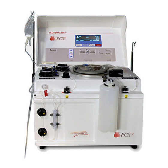
Explaining General Information What is the Using updated apheresis technology, Haemonetics has produced the PCS2 - a compact, lightweight plasmapheresis system which is as easy and safe to use as Haemonetics it is technologically advanced. Plasma The PCS2 automated apheresis technology provides the operator with a Collection maximum degree of flexibility in any type of plasmapheresis location. -
Page 12: What Are The Special Features Of The Pcs2
Explaining General Information What are the Haemonetics has incorporated advanced technological features into the portable PCS2 design. Examples of these features, which ensure safety for the donor and special features permit efficient time-management for the operator, are: of the PCS2? Self-loading pumps. -
Page 13: Understanding The Use Of Symbols
Note: Provides useful information regarding a procedure or operating tech- nique when using Haemonetics material. Caution: Advises the operator against initiating an action or creating a situa- tion which could result in damage to equipment, or impair the quality of the by-products;... - Page 14 Explaining General Information Alternating current Used to indicate on the rating plate that the device is suitable for alternating current only. Fuse symbol Used to identify fuse boxes or the location of a fuse box. Power OFF Position of the main power switch indicating disconnection from the mains. Power ON Position of the main power switch indicating connection to the mains.
- Page 15 Explaining General Information The following symbols have been designed for devices manufactured by Haemonetics: Bar-code reader connection RS232 connection RS232 connection with power to one pin Pressure cuff connection P/N 85266-30, Manual revision: A...
-
Page 16: Symbols Found On Disposable Packaging
Explaining General Information Symbols found on The following symbols are used by Haemonetics on disposable set packaging. disposable packaging CATALOG NUMBER EXPIRATION DATE Lot Number Sterilized by exposure to Ethylene Oxide Fluid path STERILE by exposure to Ethylene Oxide Sterilized by exposure to Gamma irradiation... -
Page 17: Listing Device Specifications
Operating frequency range 50 - 60 Hz 50 - 60 Hz Maximum leakage current 500 µA 100 µA Note: Haemonetics will regulate the proper voltage setting upon installation. The power source used must be properly grounded. P/N 85266-30, Manual revision: A... - Page 18 Mobile RF communication equipment not approved by Haemonetics and porta- ble communication equipment can affect the PCS2 device. Any accessories and cables not approved by Haemonetics used in conjunction with the device may increase hazards and influence compatibility with EMC requirements. Therefore, non-approved accessories and cables must not be used.
- Page 19 Chapter 2 Describing the PCS2 Device Components PRESENTING THE PCS2 DEVICE COMPONENTS ....2-3 DESCRIBING THE CENTRIFUGE SYSTEM ......2-4 System-sealing mechanism .
-
Page 20: Chapter 2 Describing The Pcs2 Device Components
Describing the PCS2 Device Components A. Cabinet 1. Centrifuge 2. Line sensor 3. Weigher 4. Anticoagulant (AC) pump 5. Blood pump 6. Donor valve (red) 7. Plasma valve (yellow) 8. Saline valve (white) 9. Donor flow lights (x2) 10. Anticoagulant line air de- tector (ACAD) 11. -
Page 21: Presenting The Pcs2 Device Components
Describing the PCS2 Device Components PCS2 RESENTING THE DEVICE COMPONENTS The components of the PCS2 device will be presented in this chapter according to where they are located on the device: The centrifuge system. The cabinet components. The control panel. 1. -
Page 22: Describing The Centrifuge System
Describing the PCS2 Device Components ESCRIBING THE CENTRIFUGE SYSTEM The centrifuge system of the PCS2 device is designed to hold a disposable bowl in which the blood components can be spun from a range of 3000 to 8000 revo- lutions per minute. This centrifugal force will separate anticoagulated whole blood into its various components. -
Page 23: System-Sealing Mechanism
Describing the PCS2 Device Components System-sealing The PCS2 centrifuge contains a split, hinged lid (or cover) and a locking knob. These components “seal” the system by: mechanism Securing the contact of the disposable bowl with the centrifuge base. Isolating the spinning bowl from the operator. Centrifuge cover The centrifuge lid, referred to as the cover, has tabs located on the rimmed portion of each split side. -
Page 24: Centrifuge Well
Describing the PCS2 Device Components Centrifuge well The PCS2 centrifuge well is designed with the following components: Optical bowl sensor There is an optical sensor located on the upper portion of the centrifuge well. The sensor is aimed at the core of the bowl and will measure optical reflection as the various blood components pass in front of the optical beam. -
Page 25: Describing The Pcs2 Cabinet Components
Weigher The weigher is the term used by Haemonetics to describe the PCS2 component which measures in grams the contents of the plasma collection container(s) placed on the weigher arm. When the Draw key is pressed to initiate a proce- dure, the weigher will automatically tare, or deduct the weight of the empty plasma collection container. -
Page 26: Pumps
Describing the PCS2 Device Components Pumps Located on the left side of the PCS2 top deck are two pumps which use peristaltic movements to displace fluids through the disposable-set tubing. Figure 2-6, PCS2 pump rotor Anticoagulant pump The AC pump, designated by the color blue, moves AC solution between the AC solution bag and the needle connector of the donor line tubing. -
Page 27: Valves
Describing the PCS2 Device Components Valves There are three valves located on the PCS2 top deck which automatically control the flow of fluids through the disposable set tubing. The valves are color-coded according to their specific functions. The PCS2 safety system will control the valves during the self-diagnostic tests. Once the operator has selected a collection procedure, the appropriate valves will automatically open, in preparation for loading the disposable set tubing. -
Page 28: Donor Flow Lights
2-10 Describing the PCS2 Device Components Donor flow lights These color-coded lights, located on both sides of the PCS2 top deck, indicate donor blood-flow status during the DRAW and RETURN modes. They are contained in a rectangular panel on the PCS2 top deck. DRAW mode Normal flow / Green Low flow / Yellow... -
Page 29: Air Detectors
Describing the PCS2 Device Components 2-11 Air detectors The PCS2 is equipped with an assembly of ultrasonic sensors designed to detect the presence of air, bubbles or foam in the fluids flowing through the disposable set tubing. If air is detected outside of the normal range during any mode (PRIME, DRAW OR RETURN), the detectors will: Alert the PCS2 safety system. - Page 30 Haemonetics recommends the following operator actions to remove any air bubbles detected in the tubing between the BLAD, DLAD1 and the DLAD2: Press the Draw key until blood enters the bowl, to send any air bubbles to the bowl.
-
Page 31: Pressure Monitors
Describing the PCS2 Device Components 2-13 Pressure The electronically controlled pressure monitors function with the correlating filter on the disposable set to measure pressure in the disposable tubing. The monitors pressure monitors provide feedback to the system about the flow of blood components. -
Page 32: Blood Filter Holder
2-14 Describing the PCS2 Device Components Warning: The operator must remain aware of the fact that a high pressure warning can indicate a possible flow obstruction and could cause red blood cell hemolysis, and/or damage the vein. Corrective action is necessary and the operator should consult the chapter “Troubleshooting During a PCS2 Procedure”, as well as the chapter “Ensuring Safety and Quality for a PCS2 Procedure“... -
Page 33: Power Entry Module
Describing the PCS2 Device Components 2-15 Power entry The power entry module is located on the left panel of the device. Externally, the module consists of an ON/OFF power switch and a power-input receptacle for module the power cord. Internally, the module contains the fuse panel. It will interrupt power supply to the system in the event of an electrical current surcharge. -
Page 34: Communication Box/Data Card (Optional)
Haemonetics communication network. HaemoNet provides any establishment (optional) using Haemonetics equipment with the possibility of linking several Haemon- etics apheresis devices to a central monitoring computer. Using HaemoNet, procedure data can be exchanged and stored in a database and/or viewed directly. -
Page 35: Describing The Pcs2 Control Panel
Describing the PCS2 Device Components 2-17 PCS2 ESCRIBING THE CONTROL PANEL The control panel, located on the inside of the hinged PCS2 cabinet cover, consists of a display screen and a keypad comprised of several groups of keys. The control panel allows the operator to interact with the system by entering appropriate data and observing feedback. - Page 36 2-18 Describing the PCS2 Device Components Procedure acronym The upper left portion of the display screen will contain the acronym selected to describe the type of procedure in progress. Display screen icons These symbols, located on the upper left side of the display screen, provide a pictorial representation of the operating state, or mode, in progress.
-
Page 37: Mode Control Keys
Describing the PCS2 Device Components 2-19 Procedure statistics area The lower portion of the screen communicates data to the operator concerning specific measurements and calculations made by the system during a PCS2 collection procedure. These statistics are updated throughout a procedure and concern the following component functions: Blood pump speed during the DRAW and RETURN modes. -
Page 38: Pump Control Keys
PCS2 procedure parameters. Certain system operating param- keys eters have been selected by Haemonetics as default values. These parameters provide optimal results in PCS2 plasmapheresis procedures with the average donor, as well as for average collection requirements. -
Page 39: Cuff Key
Describing the PCS2 Device Components 2-21 Modify Program key This key is used to access and scroll the list of procedure parameters; it can be pressed during any of the operating modes. Each time that this key is pressed, a different program parameter will be displayed on the screen, along with the current setting for that parameter. - Page 41 Returned Goods Authorization system ......3-6 HAEMONETICS® CLEANING AND MAINTENANCE RECORD ..3-8...
-
Page 42: Cleaning Procedures
The frequency of cleaning each individual PCS2 device will depend on the number of procedures performed. Special cleaning needs may arise and should be dealt with promptly. Haemonetics recommends the following routine cleaning schedule for each PCS2 device, based on an average of three collection procedures per day, or approximately sixty per month. -
Page 43: Pressure Monitors
Maintaining the PCS2 Equipment Pressure The pressure monitors (DPM/SPM) should be cleaned daily in the following manner: monitors Depress and hold the white ring as if installing the disposable filter. Wipe the silver rod thoroughly, using a circular motion and warm water. Dry the rod and release the pressure on the ring. -
Page 44: Fluid Detector
Haemonetics Technical Services provides silicon lubricant for the O-ring gasket, located at the base of the centrifuge chuck. After a major cleaning, the operator should apply a small amount of the lubricant to the gasket to prevent it from cracking. -
Page 45: Pumps
Maintaining the PCS2 Equipment Pumps The pump rotors should be removed from the well with the hexagonal head wrench. Debris should be removed from the rotors and the pump wells on a routine basis, as well as after any spills to contribute to efficient PCS2 operation. For routine cleaning, the operator should: Remove the pump rotor from the housing, using the hexagonal head wrench to remove the pump screw. -
Page 46: Customer Service
USTOMER SERVICE Clinical training Haemonetics employs a staff of Clinical Specialists to provide training for apher- esis personnel concerning the use of the PCS2 equipment. The local Haemon- etics representative will schedule staff training upon delivery of PCS2 equipment and should be contacted to organize further instruction when needed. - Page 47 Maintaining the PCS2 Equipment In some cases, it may be necessary to dispose of the contaminated goods after reporting the problem to the Haemonetics representative. This should be done according to the locally established guidelines pertaining to the disposal of biologically contaminated material.
- Page 49 Chapter 4 Ensuring Safety and Quality for a PCS2 Procedure HANDLING THE PCS2 EQUIPMENT ......4-2 Storing the PCS2 device and material .
-
Page 50: Chapter 4 Ensuring Safety And Quality For A Pcs2 Procedure
Ensuring Safety and Quality for a PCS2 Procedure PCS2 ANDLING THE EQUIPMENT Safe and successful PCS2 operation will depend in part on the proper routine handling of the PCS2 equipment. The operator should be aware of the problems which could result if the device or disposable material is stored, installed or used incorrectly. -
Page 51: Preventing Problems During A Pcs2 Procedure
“high return pressure” alarms during PCS2 operation. If there is any suspicion that hemolysis has occurred, the operator should not return the contents of the bowl to the donor. The local Haemonetics representa- tive should be informed of the problem to provide the operator with further instruction. -
Page 52: Avoiding Bowl Misalignment
Overheating could also result from a mechanical or maintenance-related problem, such as a defective bearing or seal within the centrifuge well. In this overheating due case, the operator should contact the local Haemonetics representative and to mechanical discontinue use of the PCS2 device until it is serviced. -
Page 53: Warnings For The Operator
The operator should never remove any of the PCS2 cabinet panels. Maintenance requiring access to the inner cabinet remains the responsibility of a Haemonetics- trained technician. Leakage current Each PCS2 device receives a careful inspection for leakage current prior to leaving the factory. -
Page 54: Communicable Disease Precautions
If any blood-contaminated material must be returned to Haemonetics for further inspection, the operator should consult the RGA Procedure as described in the chapter “Maintaining the PCS2 Equipment”.
Need help?
Do you have a question about the PCS 2 and is the answer not in the manual?
Questions and answers
Добрый деннь! Можно ли использовать одноразовый набор для забора крови иного производителя?