Table of Contents
Advertisement
Installation and
operating manual
WDAT-SL3 FC 200.2-580.2
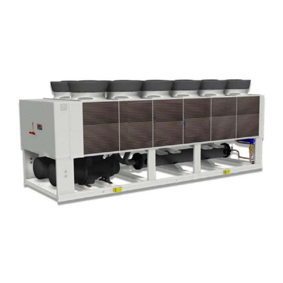
High efficiency air-cooled liquid chiller air-cooled for outdoor installation
WDAT-SL3 FC 200.2-580.2
22-05-18
M08S40E15-01
Advertisement
Table of Contents

Related Manuals for CLIVET WDAT-SL3 FC Series


Summary of Contents for CLIVET WDAT-SL3 FC Series
- Page 1 Installation and operating manual WDAT-SL3 FC 200.2-580.2 High efficiency air-cooled liquid chiller air-cooled for outdoor installation WDAT-SL3 FC 200.2-580.2 22-05-18 M08S40E15-01...
- Page 2 Yours faithfully. CLIVET Spa The data contained in this manual is not binding and may be changed by the manufacturer without prior notice. Reproduction, even is part, is FORBIDDEN © Copyright - CLIVET S.p.A. - Feltre (BL) - Italia...
- Page 3 Index of contents General description Reception Positioning Water connections Electrical connections Start-up Control Maintenance Status Accessories Decommissioning Residual risks Technical information Dimensional drawings M08S40E15-01 WDAT-SL3 FC 200.2-580.2...
- Page 4 General description 1.1 Manual The manual provides correct unit installation, use and maintenance. Pay particular attention to: Warning, identifies particularly important operations or information. Prohibited operations that must not be carried out, that compromise the operating of the unit or may cause damage to persons or things. •...
- Page 5 1.9 User training The installer has to train the user on: • Start-up/shutdown • Set points change • Standby mode • Maintenance • What to do / what not to do in case of breakdown 1.10 Data update Continual product improvements may imply manual data changes. Visit manufacturer web site for updated data.
- Page 6 Reception You have to check before accepting the delivery: • That the unit hasn’t been damaged during transport • That the materials delivered correspond with that indicated on the transport document comparing the data with the identification label positioned on the packaging. In case of damage or anomaly: •...
- Page 7 2.3 Packaging removing Be careful not to damage the unit. Keep packing material out of children’s reach it may be dangerous. Recycle and dispose of the packaging material in conformity with local regulations. M08S40E15-01 WDAT-SL3 FC 200.2-580.2...
- Page 8 Positioning During positioning consider these elements: • Technical spaces requested by the unit • Electrical connections • Water connections • Spaces for air exhaust and intake 3.1 Functional spaces Functional spaces are designed to: • guarantee good unit operation • carry out maintenance operations •...
- Page 9 3.5 AxiTop Click ! M08S40E15-01 WDAT-SL3 FC 200.2-580.2...
- Page 10 Water connections 4.1 Water quality Water features • confirming to local regulations • total hardness < 14°fr • within the limits indicated by table The water quality must be checked by qualified personnel. Water with inadequate characteristics can cause: • pressure drop increase •...
- Page 11 – to weld filettare – to thread A + B : fornito da Clivet - Clivet supplied Retirer le joint de connexion avant de souder le tuyau de l’installation. The rubber gasket might be irreparably damaged. 4.8 Flow Switch The flow switch must be present to ensure shutdown of the unit if water is not circulating.
- Page 12 4.9 Water filter Use filter with mesh pitch of 1,0 mm It must be installed immediately in the water input of the unit, in a position that is easily accessible for cleaning. The filter never should be removed, this operation invalidates the guaranty. 4.10 Operation sequence Close all vent valves in the high points of the unit hydraulic circuit Close all drain valves in the low points of the unit hydraulic circuit:...
- Page 13 Electrical connections The characteristics of the electrical lines must be determined by qualified electrica personnel able to design electrical installations; moreover, the lines must be in conformity with regulations in force. The protection devices of the unit power line must be able to stop all short circuit current, the value must be determined in accordance with system features.
- Page 14 5.5 Power supply cables section Size 200.2 210.2 220.2 240.2 260.2 280.2 320.2 Min. cable section Cu (mm²) 1x240 1x240 1x240 1x240 2x150 2x150 2x185 Max. cable section Cu (mm²) 1x240 1x240 1x240 1x240 2x300 2x300 2x300 Max. bar Cu width (mm) Tightening torque (Nm) Size 340.2...
- Page 15 5.8 Computer connection Service keypad RJ45: standard connection P.C.-not supplied P.C. connection, shift RJ45 from T-HI to T-IP Configure P.C. connect P.C. and main module with LAN cable check in the taskbar that the connection is active open Control Panel and select Network and sharing center select Modify board setting select Local area connection (LAN) select Internet protocol version 4 (TPC) IPV4 and enter Property...
- Page 16 5.9 Remote control Option Distance up to 350 mt User interface Distance up to 700 mt B = B1 KNX bus, max 350 mt twisted pair with shield, ø 0,8 mm EIB/KNX cable marking recommende PSX - Mains power supply unit pwer supply unit N125/11 5WG1 125-1AB11 AC 120...230V, 50...60Hz KNX bus, max 350 mt...
- Page 17 5.10 Modbus - RS485 Option LED BSP communication with AP1 module LED BUS communication with Modbus green communication ok green communication ok yellow software ok but communication with AP1 yellow startup / channel not communicating down flashing: software error communication down fixed: hardware error A.
- Page 18 5.11 LonWorks Option LED BSP communication with AP1 module LED BUS communication with LonWorks green communication ok green ready for communication yellow software ok but communication with AP1 yellow startup down flashing: software error flashing: communicating not possible fixed: hardware error communication down 5.12 BACnet IP Option...
- Page 19 Start-up 6.1 General description The indicated operations should be done by qualified technician with specific training on the product. Upon request, the service centres performing the start-up. The electrical, water connections and the other system works are by the installer. Agree upon in advance the star-up data with the service centre.
- Page 20 6.4 Refrigeration circuit Check carefully the refrigerating circuit: the presence of oil stains can mean leakage caused by transportation, movements or other). Verify that the refrigerating circuit is in pressure: Using the unit manometers, if present, or service manometers. Make sure that all the service outlets are closed with proper caps; if caps are not present a leak of refrigerant can be possible. Open the valves of the refrigerant circuit, if there are any.
- Page 21 6.9 Remote controls Check that the remote controls (ON-OFF etc) are connected and, if necessary, enabled with the respective parameters as indicated in the “electrical connections” section. Check that probes and optional components are connected and enabled with the respective parameters (“electrical connections” section and following pages).
- Page 22 6.11 Climatic TExt Menu accessible only after having entered the password. Access reserved only to specifically trained personnel. The parameter modification can cause irreversible damages. The setpoint defined by the temperature curve is shown at status S0010: ActualSptTExt Only if P0053: En Climatica ≠ 0 Path: Main Menu / Unit parameters / Climatica TExt Example Step Display...
- Page 23 6.12 Water reset Menu accessible only after having entered the password. Access reserved only to specifically trained personnel. The parameter modification can cause irreversible damages. It is possible to limit the absorbed electric power with an external signal 0-10 Vcc or 4-20mA. The water reset correction affects the setpoint defined by the Climate curve TExt (actual setpoint).
- Page 24 6.13 ECOSHARE function for the automatic management of a group of units • Max 7 units • Maximum length of the bus line: 1000 m. • Maximum distance between 2 units: 700 m. • Type of cable: shielded twisted pair cable Ø 0,8 mm. use an EIB/KNX cable •...
- Page 25 If there are more units connected in a local network set the mode of operation. MODE A Every unit manages its own compressors according to the setpoint. Every unit optimizes its refrigeration circuits. Pumps always active, even with compressor stoped. P0343 = 0 P0344 >...
- Page 26 The above-described operating conditions must be considered outside the operating limits. In the event of compressor breakdown, due to operating in the above-mentioned conditions, the guarantee will not be valid and Clivet spa declines any responsibility.
- Page 27 Control 7.1 Led INFO Not used ALARM Blink / fixed = alarm present CANCEL not used currently 7.2 Display Ref. Variable Description Date - Time ActualSetPoint Temperature setting T.InH2OUtilitySide Water inlet temperature utility side T.OutH2OUtilitySide Water outlet temperature utility side ActualState On / off / eco / pmp On Cool: water cooling...
- Page 28 7.4 Change unit state Step Display Action Menu/Variable Keys Notes Press Main menu Select Cmd Local state OFF - ECO - ON - Pump On Confirm Exit * Local state ECO: recurrent pump ON-OFF; compressors keep water system at setpoint ECO Pmp ON: pump ON, compressor OFF 7.5 Change the mode Step Display...
- Page 29 7.7 Display the status Step Display Action Menu/Variable Keys Notes Press Main menu Select Machine State Select General, circuit, ecc.. Exit For details see: 9 Status p. 37 7.8 Scheduler It is possible to set 6 events (Off, Eco, On, Recirculating) for each week day. Step Display Action Menu/Variable...
- Page 30 7.9 Alarms Before resetting an alarm identify and remove its cause. Repeated resets can cause irreversible damage. Example: + eE001: Monitore fase: Fault = active alarm - EE003: Guasto P1 Util: Ok = resetted alarm Display of alarm: step 1-3 Reset allarm: step 4-10 Step Display Action...
- Page 31 Input: Connector number: T1, T2, T3..PIN code: X1, X2, Q13, DO1..t.a. alarm type: A automatic reset M manual reset A/M automatic reset, (after N alarm interventions becomes manual reset) code detailed description t.i. module input t.a. eE001 Phase monitor 687 central T13 DL1 EE003...
- Page 32 code detailed description t.i. module input t.a. EE106: Compressor 1 thermal protection 985 circuit 1 T4 D1 EE107: Compressor 2 thermal protection 985 circuit 1 T4 D2 EE108: Compressor 3 thermal protection 985 circuit 1 T4 D3 EE118: Source side protection 985 circuit 1 T9 DL2 ee122:...
- Page 33 Maintenance 8.1 General description Maintenance must be done by authorized centres or by qualified personnel. The maintenance allows to: • maintain the unit efficiency • increase the life span of the equipment • assemble information and data to understand the state of the unit efficiency and avoid possible damages Before checking, please verify the following: •...
- Page 34 8.3 Unit booklet It’s advisable to create a unit booklet to take notes of the unit interventions. In this way it will be easier to adequately note the various interventions and aid any troubleshooting. Report on the booklet: • date •...
- Page 35 8.10 Air coil Contact with the exchanger fins can cause cuts: wear protective gloves to perform the above described operations. It is extremely important that the battery gives the maximum thermal exchange; therefore, its surface must be cleaned from dust and deposits. Remove all impurities from the surface.
- Page 36 8.12 Screw compressors - Periodical checks Operating hours 1000 5000 10000 15000 20000 25000 30000 Vibrations / Noise Oil level Oil filter Filter the suction Electric insulation Bearings check valve C = CHECK R = replace NO PUMP-DOWN ! 8.13 System discharge evacuate the system It is possible to limit the absorbed electric power with an external signal 0-10 Vcc or 4-20mA.
- Page 37 Status The status code identifies the concerned circuit: Example: S 1 100:CMP1 compressor1 starts = circuit 1 S 2 100:CMP1 compressor1 starts = circuit 2 The number of refrigerant circuits depends on series and size of the unit. Example: AI-687 T.IN H2OUtil_B1 Inlet water temperature AI = analogic input 687 = main module B1 = PIN...
- Page 38 code description detailed description S0012 StatusFREE-COOLING FREE-COOLING status 0=Off 1=On S0013 GenWarning 0=Off 1=On S0014 GenBlock 0=Off 1=On S0015 NCompOnUnit Number of compressors currently active on the machine 9.2 Circuit 1 status code description detailed description AI-94U SuctionTemp_X2 Suction temperature AI-94U SuctionPressureX1 Low pressure transducer...
- Page 39 code description detailed description S1106 Hours Comp.2 Compressor 2 hours S1107 Hours Comp.3 Compressor 3 hours S1108 HoursScrew Screw compressor hours S1109 HoursSource Screw compressor hours S1110 Total steps Total number of active steps on the circuit S1111 Comp.1 status Compressor 1: 0=free 1=on 2=timing 3=Disabled S1112 Comp.2 status...
- Page 40 code description detailed description AI-965 T.OutH2ORec_X3 Recovery outlet water temperature AI-965 T.OutGasRec_X1 Recovery gas outlet temperature (liquid) AO-965 %CmdPmpRec_X8 % 0-10vcc signal value recovery variable pump DI-965 EnableRec_X4 Enabling recosvery input: 0=Fault 1=OK DI-965 Ovl PmpRec_X5 Recovey thermal protection pump 0=Fault 1=OK DI-965 FlowRec_X6 Flow recovery 0=Fault 1=OK...
- Page 41 code description detailed description DO-965 CmdP3.Hid_Q1 Pump 3 command: 0=Off 1=On DO-965 ComdP3Inv.Hid_Q4 Pump 3 inverter command: 0=Off 1=On DO-965 CmdInverter:X8 Hydronic inverter command: 0=Off 1=On S0500 StartsP1Hidro Hydronic module pump 1 starts S0501 StartsP2Hidro Hydronic module pump 2 starts S0502 StartsP3Hidro Hydronic module pump 3 starts...
- Page 42 10 Accessories 10.1 direct FREE-COOLING 35°C 13°C 100% TW out TW out 10°C 10°C TW in TW in 15°C 15°C 0°C -10°C TW out TW out 10°C 10°C TW in TW in 15°C 15°C 0°C -15°C TW out TW out 7°C 6°C TW in...
- Page 43 10.2 No-glycol FREE-COOLING 13°C 35°C 100% TW out TW out 10°C 10°C TW in TW in 15°C 15°C 0°C -10°C TW out TW out 10°C 10°C TW in TW in 15°C 15°C 0°C -15°C TW out TW out 7°C 6°C TW in TW in 15°C...
- Page 44 The standard unit is supplied with antifreeze solution in the FREE-COOLING separate circuit. In option the unit is supplied without antifreeze solution. For the content of water + glycol solution refer to the table. Charging procedure The unit must be fed. Provide an external pump for the hydraulic circuit free-cooling load.
- Page 45 10.3 Partial energy recovery A configuration which enables the production of hot water free-of-charge while operating in the cooling mode, thanks to the partial recovery of condensation heat that would otherwise be rejected to the external heat source. The maximum capacity available from the partial recovery is equal to the 15% of the rejected heating capacity (cooling capacity + compressor power input) When the temperature of the water to be heated is particularly low, it is wise to insert a flow-rate control valve into the system water circuit, in order to maintain the temperature at the recovery output at above 35°C and thus avoid the condensation of the refrigerant into the partial...
- Page 46 10.4 Total energy recovery A configuration which enables the production of hot water free-of-charge while operating in the cooling mode, thanks to the partial recovery of condensation heat that would otherwise be rejected to the external heat source. Hot water availability is always subordinate to the production of chilled water. See the following example: Refrigeration capacity request Heat capacity request...
- Page 47 10.5 HydroPack Pumping unit made up of two or three electropumps laid out in parallel, with auto-adaptive modular logic activation. It enables the automatic reduction of the liquid flow rate in critical conditions, avoiding blocks due to overloading and consequential intervention work by specialised technical personnel.
- Page 48 10.6 Anti-vibration mount support WDAT-SL3 FC 200.2-580.2 M08S40E15-01...
- Page 49 M08S40E15-01 WDAT-SL3 FC 200.2-580.2...
- Page 50 WDAT-SL3 FC 200.2-580.2 M08S40E15-01...
- Page 51 11 Decommissioning 11.1 Disconnecting Only authorised personnel must disconnect the unit. Avoid leak or spills into the environment. Before disconnecting the unit, the following must be recovered, if present: • refrigerant gas • anti-freeze solutions in the water circuit Awaiting dismantling and disposal, the unit can also be stored outdoors, if the electrical, cooling and water circuits of the unit have 100% integrity and are isolated, bad weather and rapid change in temperature will not result in any environmental impact.
- Page 52 12 Residual risks General description Electric parts In this section the most common situations are indicated,as these cannot be An incomplete attachment line to the electric network or with incorrectly controlled by the manufacturer and could be a source of risk situations for sized cables and/or unsuitable protective devices can cause electric shocks, people or things.
- Page 53 FCD / FCI CONFIGURATION Acoustic configuration: compressor soundproofing (SC) General technical data - Performance Size 200.2 210.2 220.2 240.2 260.2 280.2 320.2 340.2 360.2 400.2 440.2 500.2 540.2 580.2 Cooling Cooling capacity [kW] 1058 1183 1272 1375 Compressor power input [kW] Total power input [kW]...
- Page 54 FCD / FCI CONFIGURATION Acoustic configuration: compressor soundproofing (SC) General technical data - Construction Size 200.2 210.2 220.2 240.2 260.2 280.2 320.2 340.2 360.2 400.2 440.2 500.2 540.2 580.2 Compressor Type of compressors No. of compressors Rated power (C1) [HP] Nominal capacity (C2) [HP] Std Capacity control steps...
- Page 55 FCD / FCI CONFIGURATION Acoustic configuration: super-silenced (EN) General technical data - Construction Size 200.2 210.2 220.2 240.2 260.2 280.2 320.2 340.2 360.2 400.2 440.2 500.2 Compressor Type of compressors No. of compressors Rated power (C1) [HP] Nominal capacity (C2) [HP] Std Capacity control steps 25-100%...
- Page 56 Operating range FCD / FCI CONFIGURATION Acoustic configuration: compressor Acoustic configuration: super-silenced (EN) soundproofing (SC) Ta (°C) = external exchanger inlet air temperature (D.B.) Ta (°C) = temperatura aria entrante allo scambiatore esterno (D.B.) To (°C) = internal exchanger outlet water temperature To (°C) = internal exchanger outlet water temperature Standard unit operating range at full load Standard unit operating range at full load...
- Page 57 Admissible water flow-rates Minimum (Qmin) and maximum (Qmax) admissible water flow for the unit to operate correctly. EXCELLENCE SC 200.2 210.2 220.2 240.2 260.2 280.2 320.2 340.2 360.2 400.2 440.2 500.2 540.2 580.2 Qmin [l/s] 15.3 15.3 20.1 20.1 20.1 21.6 21.6 21.6...
- Page 58 Dimensional drawings - FCD configuration (Direct FREE-COOLING) Size 200.2-210.2 - Acoustic configuration: compressor soundproofing (SC) 1. Internal exchanger (evaporator) 5. Electrical panel 2. External exchanger (condenser) 6. Power input 3. Unit fixing holes 7. Sound proof enclosure ( only in the relevant versions) 4.
- Page 59 FCD configuration (Direct FREE-COOLING) Size 220.2-240.2 - 260.2 - Acoustic configuration: compressor soundproofing (SC) Size 200.2-210.2 - 220.2 - Acoustic configuration: super-silenced (EN) 1. Internal exchanger (evaporator) 5. Electrical panel 2. External exchanger (condenser) 6. Power input 3. Unit fixing holes 7.
- Page 60 FCD configuration (Direct FREE-COOLING) Size 280.2-320.2 - Acoustic configuration: compressor soundproofing (SC) Size 240.2-260.2- Acoustic configuration: super-silenced (EN) 1. Internal exchanger (evaporator) 5. Electrical panel 2. External exchanger (condenser) 6. Power input 3. Unit fixing holes 7. Sound proof enclosure ( only in the relevant versions) 4.
- Page 61 FCD configuration (Direct FREE-COOLING) Size 340.2-360.2 - Acoustic configuration: compressor soundproofing (SC) Size 280.2 - Acoustic configuration: super-silenced (EN) 1. Internal exchanger (evaporator) 5. Electrical panel 2. External exchanger (condenser) 6. Power input 3. Unit fixing holes 7. Sound proof enclosure ( only in the relevant versions) 4.
- Page 62 FCD configuration (Direct FREE-COOLING) Size 400.2-440.2 - Acoustic configuration: compressor soundproofing (SC) Size 320.2 - 340.2 - 360.2 - Acoustic configuration: super-silenced (EN) 1. Internal exchanger (evaporator) 5. Electrical panel 2. External exchanger (condenser) 6. Power input 3. Unit fixing holes 7.
- Page 63 FCD configuration (Direct FREE-COOLING) Size 500.2-540.2 - 580.2 - Acoustic configuration: compressor soundproofing (SC) Size 400.2 - 440.2 - 500.2 - Acoustic configuration: super-silenced (EN) 1. Internal exchanger (evaporator) 5. Electrical panel 2. External exchanger (condenser) 6. Power input 3. Unit fixing holes 7.
- Page 64 FCI configuration (No-glycol FREE-COOLING) Size 200.2 - 210.2 - Acoustic configuration: compressor soundproofing (SC) 1. Internal exchanger (evaporator) 5. Electrical panel 2. External exchanger (condenser) 6. Power input 3. Unit fixing holes 7. Sound proof enclosure ( only in the relevant versions) 4.
- Page 65 FCI configuration (No-glycol FREE-COOLING) Size 220.2 - 240.2 - 260.2 - Acoustic configuration: compressor soundproofing (SC) Size 200.2 - 210.2 - 220.2 - Acoustic configuration: super-silenced (EN) 1. Internal exchanger (evaporator) 5. Electrical panel 2. External exchanger (condenser) 6. Power input 3.
- Page 66 FCI configuration (No-glycol FREE-COOLING) Size 280.2 - 320.2 Acoustic configuration: compressor soundproofing (SC) Size 240.2 - 260.2 Acoustic configuration: super-silenced (EN) 1. Internal exchanger (evaporator) 5. Electrical panel 2. External exchanger (condenser) 6. Power input 3. Unit fixing holes 7. Sound proof enclosure ( only in the relevant versions) 4.
- Page 67 FCI configuration (No-glycol FREE-COOLING) Size 340.2 - 360.2 Acoustic configuration: compressor soundproofing (SC) Size 280.2 - Acoustic configuration: super-silenced (EN) 1. Internal exchanger (evaporator) 5. Electrical panel 2. External exchanger (condenser) 6. Power input 3. Unit fixing holes 7. Sound proof enclosure ( only in the relevant versions) 4.
- Page 68 FCI configuration (No-glycol FREE-COOLING) Size 400.2 - 440.2 Acoustic configuration: compressor soundproofing (SC) Size 320.2 - 340.2 - 360.2 Acoustic configuration: super-silenced (EN) 1. Internal exchanger (evaporator) 5. Electrical panel 2. External exchanger (condenser) 6. Power input 3. Unit fixing holes 7.
- Page 69 FCI configuration (No-glycol FREE-COOLING) Size 500.2 - 540.2 - 580.2 Acoustic configuration: compressor soundproofing (SC) Size 400.2 - 440.2 - 500.2 Acoustic configuration: super-silenced (EN) 1. Internal exchanger (evaporator) 5. Electrical panel 2. External exchanger (condenser) 6. Power input 3. Unit fixing holes 7.
- Page 70 Tel. + 34 91 6658280 - Fax + 34 91 6657806 - info@clivet.es CLIVET GmbH Hummelsbütteler Steindamm 84, 22851 Norderstedt - Germany Tel. + 49 (0) 40 32 59 57-0 - Fax + 49 (0) 40 32 59 57-194 - info.de@clivet.com CLIVET RUSSIA Elektrozavodskaya st. 24, office 509 - 107023, Moscow, Russia Tel.
Need help?
Do you have a question about the WDAT-SL3 FC Series and is the answer not in the manual?
Questions and answers
How to remove ee118 error wdat.sl3.400.2