Table of Contents
Advertisement
Quick Links
Advertisement
Table of Contents

Related Manuals for Panduit SmartZone EPA126


Summary of Contents for Panduit SmartZone EPA126
- Page 1 Remote Logger Unit User Manual Release 1.0 Issue 1.0...
- Page 2 Remote Logger Unit User Manual Copyright © 2014 Panduit Corp. All rights reserved. No part of this book shall be reproduced, stored in a retrieval system, or transmitted by any means, electronic, mechanical, photocopying, recording or otherwise, without written permission from Panduit. No patent liability is assumed with respect to the use of the information contained herein.
-
Page 3: Table Of Contents
Remote Logger Unit User Manual Table of Contents Remote Logger Unit Environment Monitoring PDU Monitoring Contacting Panduit Document Overview Document History Remote Logger Unit Package Front of RLU Rear of RLU LEDs Reset Button Connections Rack Mounting Equipment Required Before You Begin... - Page 4 Remote Logger Unit User Manual Appendix A: Technical Details Factory Default Settings Operating Information - 4 -...
-
Page 5: Remote Logger Unit
Contacting Panduit For Technical Support on PIM Software, please contact Panduit Technical Support using one of the following methods: Toll-Free: 1-866-721-5302, Monday-Friday, 24 hours/day... -
Page 6: Document Overview
Remote Logger Unit User Manual Document Overview This manual uses the following typographic conventions: Italics surrounded by curly braces indicate a user supplied {somevalue} entry that must be input. E.g.: {drive}:\setup Text surrounded by angled brackets indicate specific keys to <ctrl+alt+delete>... -
Page 7: Remote Logger Unit Package
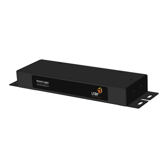
Remote Logger Unit User Manual Remote Logger Unit Package The standard RLU package contains a Remote Logger Unit and a Localized Mains Lead. Front of RLU The following image shows the front panel of the Remote Logger Unit: Rear of RLU The following image shows the rear panel of the Remote Logger Unit: LEDs LEDs can be found on the rear of the RLU. -
Page 8: Reset Button
Remote Logger Unit User Manual Reset Button The back of the RLU includes a Reset button, which allows the user to reboot the unit. Connections On the rear of the RLU are several connectors: Power Monitoring: PDUs connect here Inputs: Probes are connected here Serial Port: For connection of a smart meter or serial terminal USB: For connection of a USB device such as a serial terminal GSM: For connection of a GSM aerial... -
Page 9: Rack Mounting
Remote Logger Unit User Manual Rack Mounting This section covers the basic bracket mounting of the RLU. Equipment Required You need to supply a minimum of two 5mm x 15mm pan head or hexagonal head bolts, two 5mm washers and nuts, and the appropriate tools. Before You Begin When determining where to install the RLU, please verify that these guidelines are met: Airflow around the RLU is unrestricted. -
Page 10: Rack-Mount The Rlu
Remote Logger Unit User Manual Reliable earthing of rack-mounted equipment should be maintained. Particular attention should be given to supply connections other than direct connections to the branch circuit (use of a power strip etc). Rack-Mount the RLU Hold the RLU and attach the bracket to the rack using two 12-24 screws. - 10 -... -
Page 11: Initial Setup
Remote Logger Unit User Manual Initial Setup Installation Requirements Remote Logger Unit. IEC mains lead (supplied localized). Computer system with serial terminal emulator program to set up the RLU. Serial lead (see below). Connection to Configuration Interface The Remote Logger Unit can be configured entirely using the command line interface accessible via the RS232 and USB ports. -
Page 12: Default Network Settings
Remote Logger Unit User Manual Default Network Settings To determine the default network settings enter the following at the CLI: type autoapn This will list the file containing all available network configurations. To determine whether or not your network is configured you need to determine its IMSI and check whether the first digits of this code appear as any of the network IDs (first field in each data line) of the data returned. -
Page 13: Logging Setup
Remote Logger Unit User Manual CONFIG SERVER The server updates are configured as follows: UI <interval> sets the interval (in seconds) between successive server update operations. UI_SYNC <time> sets a server update synchronization point (format: HHSS) in the current 24-hour period. FW_NAME <fname>... -
Page 14: Utl Pdus
Remote Logger Unit User Manual <Port> is the physical port to which the meter is connected (1 through 4). <addr> is the base address of the meter if it is a Modbus device; otherwise the value is set to 0. <baud>... -
Page 15: Modbus Devices
Remote Logger Unit User Manual Modbus Devices The types of digital sensors are: ND MultiCube ND 350 For ND 350 <numslvs> should be 0. Limits The thresholds that can be set are: kWh Upper Threshold kWh Lower Threshold Limits may be configured as follows: PWR ALARMSET <id>,<s1lt>,<s1ht>[;<snlt>,<pnht>]... -
Page 16: Probe Templates
Remote Logger Unit User Manual Probe Templates The format of a template is as follows: <template> = <id>,<name>,<p0>,<p1>,...,<pn> To read back the template for a particular probe id use: env template <id> To install a new template for a particular probe id use: env template <template>... -
Page 17: Limits
Remote Logger Unit User Manual For digital sensors the template supplies a set of integer values defining open circuit state and de-bounce counts (high and low) for each port. This set of values has the fol- lowing format: <o1>,<o2>,<o3>,<o4>,<o5>,<o6>,<h1>,<h2>,<h3>,<h4>, < h5>,<h6>, < l- 1>,<l2>,<l3>,<l4>,<l5>,<l6>... -
Page 18: Serial Port
Remote Logger Unit User Manual Serial Port To update firmware via the serial port, enter the following command at the terminal: ymodem fw Then use the Y Modem facility to send the application firmware update to the RLU. On completion, restart the RLU by pressing Reset, and the new firmware version will install and start to execute. -
Page 19: Troubleshooting
Remote Logger Unit User Manual Troubleshooting Resetting the RLU to Factory Default Settings To reset the Remote Logger Unit to the factory default, perform the following steps: Note: This process is best accomplished from the back side of unit (the side with the con- nectors). - Page 20 Remote Logger Unit User Manual Appendix A: Technical Details Factory Default Settings SmartZone EPA126 Gateway Defaults IP Address 192.168.0.253 Subnet Mask 255.255.255.0 (/24) Default Gateway 192.168.0.1 Web Management Address http://192.168.0.253/ Default Username admin Default Password admin Operating Information Input Power...
Need help?
Do you have a question about the SmartZone EPA126 and is the answer not in the manual?
Questions and answers