Table of Contents
Advertisement
Quick Links
Advertisement
Table of Contents

Related Manuals for Panduit Synapsense


Summary of Contents for Panduit Synapsense
- Page 1 Intelligent Gateway Installation Manual...
-
Page 2: Table Of Contents
Contents About This Guide ......................3 Industry Canada Statement ..................3 Organization ........................ 3 Document Conventions ....................3 Warnings and Precautions ................... 4 Introduction ........................5 Hardware Detail ......................6 Getting Started ........................ 7 Kit Components ......................7 Tools and Materials ..................... 9 Installation and Configuration .................. - Page 3 Inspect Software Communication ................23 Troubleshooting ......................25 Gateway Testing ......................25 LED behavior for Gateway Status ................25 LED Behavior for Radio Activity ................25 Issues and Solutions ....................26 INTELLIGENT GATEWAY INSTALLATION MANUAL...
-
Page 4: About This Guide
This document provides guidelines and instructions for installing and configuring the SynapSense Intelligent Gateway device. The intended audience for this document consists of customers or partners of SynapSense Corporation or a SynapSense installer (or installation team). Customers, partners, or installers should receive training from SynapSense prior to installing the hardware detailed in this document. -
Page 5: Warnings And Precautions
This triangular yellow electrical icon denotes a SAFETY WARNING of a physical or electrical nature. Warnings and Precautions The following warnings and precautions pertain to SynapSense Intelligent Gateway installations. Failure to adhere to warnings and precautions could result in physical injury or damage to equipment, which may void the warranty. -
Page 6: Introduction
The SynapSense Intelligent Gateway™ is an Ethernet to wireless network bridge designed to collect data from any of the SynapSense wireless sensors or to meter hardware and send the data to a remote server. It is also designed to operate in standalone mode for some time if the Ethernet connection is lost. -
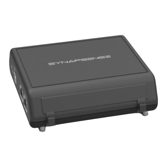
Page 7: Hardware Detail
Hardware Detail The Gateway is 5.5in x 5.25in x 1.63in. The Gateway can be used in a variety of mounting locations and orientations such as on the tops of racks, on wall mounts, or zip-tied to other structures. The Unit Status LED shining solid blue or solid green means the unit is functioning normally. -
Page 8: Getting Started
Port 80 = Configuration via the Gateway’s web page. Port 10001 = Data received from SynapSense wireless sensors. When adding a gateway to an existing wireless network, verify that your nodes have SynapSense firmware version 29.4 or higher, software version 6.7 or higher, and applicable documentation. - Page 9 • One (1) DC Power Adapter (to convert 90-264 VAC wall power to +5VDC) • Two (2) power cables (one C13 to NEMA 5, and one C13 to C14). Be sure to use the correct power supply for this unit. •...
-
Page 10: Tools And Materials
Tools and Materials The table below lists the minimum tools and additional material requirements that SynapSense Field Engineers and contracted electricians must bring to the job site. Table of Tools and Materials Item Description/Comments Attire Proper dress and shoes for performing work in a data center (including areas... -
Page 11: Installation And Configuration
Network Considerations The SynapSense Intelligent Gateway connects to your network using the Data port. The gateway supports IPv4 Dynamic/Static IP addresses or IPv6 Static IP addresses. When using dynamic addressing, the gateway relies on an external DHCP server for IP... -
Page 12: Pre-Installation Decisions
– Before installation, a decision must be made about where to run Device Manager. The Device Manager can run on either ONE SynapSense Intelligent Gateway or on the SynapSense Environment Server. The Device Manager cannot be running in both locations or on more than one gateway. -
Page 13: Data Port Setup Tab
To connect the gateway to the laptop Connect the correct power cable to the gateway’s power adapter. Plug the 5VDC cord into the Gateway power port marked 5VDC, then plug it into a power outlet. Confirm that your computer’s network interface is enabled and configured for DHCP. Unless configured otherwise, the gateway will dynamically assign an IP address (IPv4, 192.168.1.100) to the computer connected to the Gateway Configuration Port. - Page 14 For Static IPv4, do the following: Static Select the radio button. IP address Subnet mask b. Enter the . Other fields are optional. Ensure the static addresses on the configuration port and the data port are on different subnets. Apply Click For Static IPv6, do the following: Complete Step 6 to configure the IPv4 section.
-
Page 15: Configuration Port Setup Tab
On the Device Manager tab, verify the information in the Environment Server address and NTP (Network Time Protocol) Server fields. If an NTP server is not available due to the SynapSense hardware existing in a private network, please follow the instructions given in the... -
Page 16: Password Tab
Click the checkbox for Enable Device Manager. Click to start Device Manager on the Gateway. If Device Manager starts properly but does not yet have connectivity to the SynapSense Environment Server, the Status LED on the Gateway will blink Red and Blue. -
Page 17: Firmware Update
Disconnect DM – Closes communication between the gateway and the Device Manager process. This may be performed at the request of SynapSense Customer Support, when the existing connection is hung or not working appropriately. System Reboot – Reboots the Gateway. -
Page 18: Gateway Installation
Navigate to the location where you saved the firmware update file. Click to select the file, then click to close the dialog and start the upload process. A progress bar displays during the upload. Upgrade Once the file upload is complete, two new buttons display: Upgrade and Purge. Select proceed with the update, then click to close the verification message. -
Page 19: Gateway Mounting Shelf
The Gateway Mounting Shelf is designed for use with both the SynapSense Intelligent Gateway and the smaller SynapSense Remote Gateway 2. Screws and other associated hardware for mounting the Gateway Mounting Shelf are not included in the SynapSense Gateway kits and must be supplied by the customer. To mount a gateway shelf Using the holes on the mounting shelf as a template, position the shelf in the desired location (i.e.,... - Page 20 The Unit Status LED will blink RED continuously when the unit is ON. Insert the Gateway mounting spacers into the front mounting holes for the larger SynapSense Intelligent Gateway and slide the Gateway downward to bottom of mounting hole slots.
-
Page 21: Zip-Tie Mount
Final Installation Activities section. Zip-tie Mount Zip-ties are the most common type of mount in SynapSense installations due to the fact that most racks have perforated tops to allow heat to escape. To mount a gateway with Zip-ties Thread the Zip-tie through the four zip-tie hold downs that are part of the Gateway case then through the holes of the mesh top of the rack. -
Page 22: 3M Command Strip
Connect the designated Ethernet Cable (originating from a server port assigned by the data center's IT department) to the Gateway. The Radio Activity LED will remain ON to indicate on-going radio communication activity. The Unit Status LED will remain OFF unless there is a problem. See Troubleshooting for a table of status colors. -
Page 23: Final Installation Activities
When all Gateways are installed, proceed to the Final Installation Activities section. Final Installation Activities Perform the following activities to complete the Gateway installation. Clean installation area of debris (packaging etc.). Dispose of trash appropriately. Proceed to Chapter 4, Installation Inspection. -
Page 24: Installation Inspection
Installation Inspection Inspections ensure installations are correct and Gateway devices communicate with SynapSense Web Console™. Inspect Operations and Appearance Verify all installed Gateway devices are connected properly (Power Adapter, Ethernet Cable, etc.) and receiving power. Verify Gateway devices are installed in areas in which there is a clear line of sight for wireless sensors radio transmissions. - Page 25 Figure 1 – Accessing Web Console Data Center Floor plan The screen refreshes and displays the wireless sensor network (including Gateways) for the data center. Place your cursor over a Gateway device on the display. The name and status of the device displays next the Gateway graphic representation (see Figure 2).
-
Page 26: Troubleshooting
Period Solid During power-on and boot process the light shows solid red for the first 30 seconds. If light remains on continuously, contact SynapSense Customer Support. Blinking Power cycle the Gateway. Once power is off, wait 30 seconds before turning power back on. -
Page 27: Issues And Solutions
The following issues have occurred during testing and may occur in the field. If what you encounter is not in the list below, contact SynapSense Customer Support. Issue: I am able to login to the SynapSense Intelligent Gateway, but the user interface looks garbled, broken, or is unresponsive. - Page 28 Once the gateway is properly configured, connected, and assigned an IP address on the Data port, the gateway’s web interface can be accessed via the Data port interface/network. Issue: How do I determine the IP address of the SynapSense Intelligent Gateway connected to my network via the Data Port? Solution: We recommend the gateway be connected to a network that provides DHCP/DNS registration and hostname resolution.
- Page 29 For example: 172.30.200.146 SynapSenseGW02 Save the “hosts” file. Issue: Why are nodes not joining the WSN network and reporting to the SynapSense Web Console? Solution 1: Confirm the SynapSense software installation has completed, installing all desired software components. See Control Panel > Programs and Features > SynapSoft...
- Page 30 Next Select the location where you want to place the NTP, then click Next In the Choose Components window, accept the defaults, then click INTELLIGENT GATEWAY INSTALLATION MANUAL...
- Page 31 None In the drop-down list for using a predefined public NTP server, select Next Check the box for “Add local clock as a last resort reference, Stratum 12”, then click Click to verify the configuration. INTELLIGENT GATEWAY INSTALLATION MANUAL...
- Page 32 Select the System account radio button (even though it is not recommended), then click Finish 10. Click At this point, the server IP address can be used in the NTP address field for the SynapSense Intelligent Gateway. See Device Manager Tab. INTELLIGENT GATEWAY INSTALLATION MANUAL...
- Page 33 During the initial software installation (while running as Administrator), use the Windows Time Service W32TM commands to synchronize the local time on the SynapSense Server to an external reference, such as time.nist.gov. This requires the server to have access to an external DNS (or proxy) during the initial setup.
Need help?
Do you have a question about the Synapsense and is the answer not in the manual?
Questions and answers