Advertisement
Quick Links
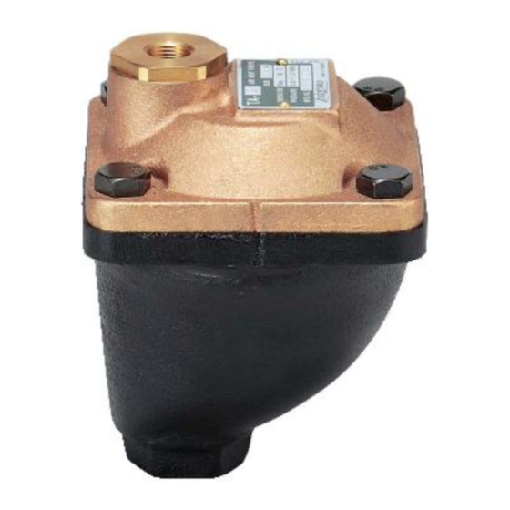
Model TA
Model TA-2・ ・ ・ ・ 2C・ ・ ・ ・ 5・ ・ ・ ・
Thank you very much for choosing the Yoshitake's product. To ensure the correct and safe use of the product,
Thank you very much for choosing the Yoshitake's
please read this manual before use. This
The symbols used in this manual have the following meanings.
The symbols used in this manual have the following meanings.
Warning
Caution
2. Features ································
3. Specifications
5. Operation ································
6. Maintenance ································
7. Disassembly ································
Warranty Information
Warranty Information
Air Vent Valve
Air Vent Valve
INSTRUCTION MANUAL
INSTRUCTION MANUAL
This manual shall be kept with care for future references
This symbol indicates a potentially hazardous situation that, if not avoided,
This symbol indicates a
could result in death or serious injury.
could result in death or serious injury.
This symbol indicates a hazardous situation that, if not avoided, may result in
This symbol indicates a hazardous situation that, if not avoided, may result in
This symbol indicates a hazardous situation that, if not avoided, may result in
minor or moderate injury
minor or moderate injury or may result in only property damage.
Product ··················································
··································································
and Performance ····································
Dimensions and Weights ·············································
································································
·····························································
Precautions for operation ·······································
.2 Precaution for use ················································
Troubleshooting ···················································
·····························································
Precaution for maintenance ····································
Disassembly procedure ·········································
···························································
product. To ensure the correct and safe use of the product,
potentially hazardous situation that, if not avoided,
or may result in only property damage.
Table of Contents
································· 3
····························· 4
····························· 4
··························· 5
・ ・ ・ ・ 5F
for future references.
·················· 1
·· 1
···· 1
············· 2
······· 4
················ 4
··················· 4
···· 4
········· 5
.
E PDT-198
■
■
Advertisement

Related Manuals for Yoshitake TA-2


Summary of Contents for Yoshitake TA-2
-
Page 1: Table Of Contents
INSTRUCTION MANUAL Thank you very much for choosing the Yoshitake’s Thank you very much for choosing the Yoshitake’s product. To ensure the correct and safe use of the product, product. To ensure the correct and safe use of the product, please read this manual before use. -
Page 2: Usage Of The P Product
Ingress of air into the piping system causes degrease of heat efficiency, noise generation or corrosion of devices, etc. Air ve , noise generation or corrosion of devices, etc. Air vent valves TA-2, 2C, 5, 5F equip 2, 2C, 5, 5F equip quick exhaust... -
Page 3: Dimensions And Weights Dimensions And Weights
Quick exhaust hole (mm) Nominal *Weight (kg) size Rc 1/2 Rc 3/8 3.18 Rc 3/4 Rc 3/8 3.18 Rc 1 Rc 3/8 3.22 Rc 1 1/4 Rc 3/8 3.22 *The weight is for TA-2 2 C. ・ E PDT-198 ■ ■... -
Page 4: Operation
5. Operation (1) Before water flowing, the float [7] is in low position and the floating valve [2] is opened. F ig. 4-1 【 】 (2) When water starts to flow into the valve, air inside piping is pushed by water and exhausted out through quick exhaust hole. -
Page 5: Maintenance
6. Operating Procedure 5.1 Precautions for operation Caution 1. Install the product perpendicular Install the product perpendicularly on such a place where air likely gathers. *Failure to follow this notice does not achieve does not achieve function of the product. 2. -
Page 6: Disassembly Disassembly Procedure
7.2 Disassembly procedure (1) Remove the valve seat by using a spanner (width across flat: 36 mm). (2) Remove the O ring (P-28) (3) Remove the floating valve. (4) Remove the clamping bolt (M10) of the cover. (5) Remove the pin fixing the float and then remove the float. (6) Remove the cross recessed pan head machine screw (M4) (by using a cross slot screwdriver).