Table of Contents
Advertisement
Advertisement
Table of Contents

Related Manuals for NKT Photonics SUPERK SELECT


Summary of Contents for NKT Photonics SUPERK SELECT
- Page 1 SuperK SELECT Multi Channel Tunable Filter PRODUCT GUIDE...
- Page 2 This guide includes the following NKT Photonics products: SuperK SELECT Multi Channel Tunable Filter Item number: A203-XXX-XXX SuperK External RF Driver RF Signal Generator Item number: A901-100-000 SuperK COMMAND Fast Wavelength Switching Signaling Interface Item number: A203-000-001 SuperK SELECT Product Guide Revision 1.00 10-2020 W-10456...
-
Page 3: Guide Overview
A USB memory stick is included. It contains documentation for all NKT Photonics products including this accessory. Terminology The guide may refer to the SuperK SELECT as the SELECT, device or accessory. Target Audience This guide is for technical personnel involved in the selection, planning and deployment of lasers and photonic equipment in laboratory and industrial settings. - Page 4 Added information Lasers with their accessories are highly dangerous devices that can cause and Safety Notices serious injury and property damage. This guide use the following symbols to either highlight important safety information or provide further information in relation to a specific topic. Note: Highlights additional information related to the associated topic and/or pro- vides links or the name of the NKTP guides describing the additional information.
-
Page 5: Table Of Contents
Optical apertures ....................21 Monitor ports ....................... 22 Electrical Interfaces .....................23 External RF driver ..................... 24 ERD - rear panel ....................25 SuperK SELECT Control ..................26 Software Description ..................26 Status LEDs ........................ 26 Chassis labels......................28 2 Installation ..........................31... - Page 6 General ........................31 Optical Connections ....................32 Inserting the SuperK collimator ............... 32 Optical output ...................... 33 Electrical Connections..................... 33 Single ERD system ..................... 33 Dual ERD system ....................35 Adding additional accessories .................37 3 Output Power Considerations ..................39 Output beam quality ....................
- Page 7 C CONTROL Software ......................63 Installing CONTROL....................63 D Using a SuperK COMMAND module ................69 Description......................... 69 Connect to a SuperK SELECT system ............70 External signal requirements ................71 Signaling and CONTROL configuration..............71 2 or 4-channel FWS .....................71 Four 8-channel profile switching ..............72 16-channel FWS ....................74...
-
Page 9: Tables
TABLES Table 1: AOTF crystal models – wavelength bands (nanometers) ......16 Table 2: SELECT Status LEDs ....................27 Table 3: Chassis labels ....................... 28 Table 4: Optical ........................57 Table 5: Interfaces .......................57 Table 6: Mechanical dimensions ..................57 Table 7: Electrical specifications – External RF Drivers ..........57 Table 8: Operating and storage environment ............. -
Page 11: Figures
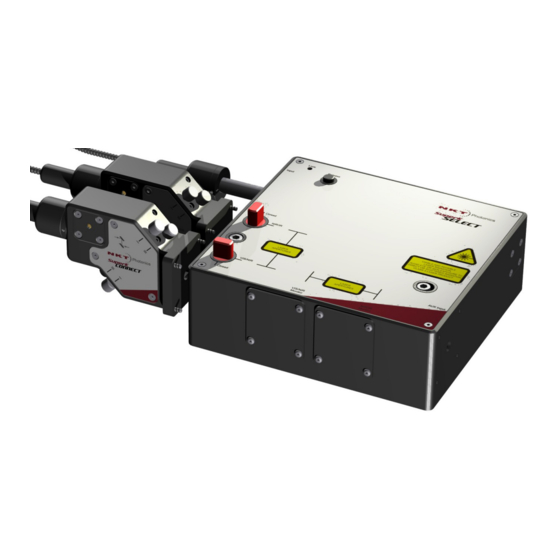
FIGURES Figure 1: SuperK SELECT with dual AOTF outputs – general view ......15 Figure 2: SuperK SELECT standard dual RF driver system view ......17 Figure 3: Primary output shutters – VIR/NIR set open and NIR/IR set closed ..18 Figure 4: Top panel ...................... - Page 12 Figure 29: Device selector ....................44 Figure 30: Device selector set to 0xE bus address ........... 44 Figure 31: Status Panel ....................... 45 Figure 32: CONTROL settings ..................47 Figure 33: Setup menu page .................... 47 Figure 34: CONTROL settings ..................49 Figure 35: Channel controls - general operation ............50 Figure 36: Set button sliders .....................
-
Page 13: Procedures
PROCEDURES Procedure 1: Inserting a SuperK output collimator ............. 32 Procedure 2: Electrical connections for a SELECT with a single ERD....33 Procedure 3: Electrical connections for a SELECT with dual ERDs ....... 35 Procedure 4: Connecting additional accessories............37 Procedure 5: Remapping the optimum RF power level.......... -
Page 15: Description
Description The SuperK SELECT is a plug & play filter accessory for the SuperK series of lasers. The filter can tune and select multiple wavelengths from the emission spectrum of a SuperK laser. The SELECT also includes a range of unique features... -
Page 16: Aotf Crystal Types
AOTF crystal types The SELECT can be specified with a variety of AOTF crystals that can filter wavelengths from the SuperK emission spectrum from 400 to 2000 nm. Table 1 lists the crystal models available and the combinations which can be fitted in a dual AOTF SELECT. -
Page 17: Rf Driver
RF driver An NKT Photonics External RF Driver (ERD) unit is connected to the SELECT’s RF1 input. The ERD generates the necessary RF signals to drive a single AOTF crystal. The RF signals generated by the driver are configured to drive an AOTF for up to 8 output wavelengths. -
Page 18: Features
Connections” on page Shutters As a safety feature, each primary optical output of the SuperK SELECT is equipped with a mechanical shutter. When the shutter is closed, it blocks all optical emission. The shutters are manually operated by turning the shutter knob between the Open... -
Page 19: Interfaces
Release button (6). When the collimator is inserted, use the nearby locking screw to securely fasten it. Mounting holes The two mounting holes (2) are designed to fasten the SuperK SELECT to either metric or imperial optical tables that have screw holes spaced at either 25 mm or 1” pitch. - Page 20 This is an IR output where unused and unfiltered light from the input SuperK laser is emitted from the SELECT. The port is intended for use with for example another SuperK SELECT operating at higher wavelengths. When not used, a cover plate is mounted on the aperture to block emission.
-
Page 21: Optical Apertures
Optical apertures Optical apertures are located on two of the side panels of the SELECT as shown and described in the following. Figure 5 Figure 5 Optical Interfaces Optical input aperture 3 VIS/NIR output aperture NIR/IR output aperture – with shipping 4 Monitor optical output apertures –... -
Page 22: Monitor Ports
Monitor ports Monitor ports are located on the side panels of the SELECT as shown in Figure 5 The ports and connectors shown in the figure are optionally fitted with power monitors before leaving the factory. The power monitors receive a fraction of the VIS/NIR and NIR/IR output beams. -
Page 23: Electrical Interfaces
Electrical Interfaces shows the electrical interfaces located on a side panel of the SELECT. Figure 7 Figure 7 Electrical Interfaces ad optical input Monitor output 6 RF Power I LED Accessory bus address selector Bus through port (External bus output) RF Power II LED 8 Bus input port (External bus input) RF Power II input... -
Page 24: External Rf Driver
SuperK output spectrum. The ERD is connected to the External bus of the SuperK laser system and is managed using NKT Photonics CONTROL software. Based on the configuration in CONTROL and the AOTF calibration, the ERD transmits an appropriate RF signal to an AOTF crystal. -
Page 25: Erd - Rear Panel
External RF driver ERD - rear panel Figure 9 External RF Driver – rear panel Power/comms and interlock LEDs Address selector (external bus) Modulation connector Bus through port (external bus) PWM – reserved for future use Bus input (external bus) RF USB –... -
Page 26: Superk Select Control
SuperK SELECT Control AC ON/OFF switch Toggles AC power on or off to the ERD. SuperK SELECT Control Software Both the SuperK laser and the SELECT accessory are controlled using NKT Description Photonic’s CONTROL management software installed on a PC or the front panel interface. -
Page 27: Table 2 Select Status Leds
Status LEDs Figure 10 SELECT Status LEDs Power Interlock Emission Table 2 SELECT Status LEDs LED Name Condition Description Emission ON RED Emission enabled The SuperK laser system emission is ON and class 4 emission is present at the primary and auxiliary optical output ports. -
Page 28: Chassis Labels
Status LEDs Chassis labels The SuperK SELECT chassis includes multiple labels that indicate hazards and safety and product information. The labels are located on the panels as described in with the panels shown in Table 3 Figure 11 Figure Table 3 Chassis labels... -
Page 29: Figure 12 Top Panel Labels
Status LEDs Figure 12 Top panel labels 3 Class 4 Laser Radiation Warning Laser Apertures Laser Radiation Warning NOTE: Laser apertures are located on the side panel below the label. - Page 30 Status LEDs...
-
Page 31: Installation
General All chassis types must be installed on a level surface that is free from vibrations. The SuperK SELECT can be fastened to both metric and imperial optical tables. The ambient temperature surrounding the laser and SELECT system should be stable and free from anything that could cause temperature fluctuations. -
Page 32: Optical Connections
Optical Connections Caution: The SuperK SELECT is intended for use with the SuperK Class 3B and 4 lasers systems only. Using the SuperK SELECT with a laser source other than a Su- perK laser may result in hazardous radiation exposure. Warning: To operate these systems, you must be familiar with laser safety regula- tions and have received instruction in the safe use of lasers. -
Page 33: Optical Output
2.5 mm hex key Inserted collimator Optical output All optical outputs are free space> NKT Photonics can provide SuperK CONNECT accessories and collimators as described in the document: SuperK CONNECT and Fiber Delivery Product Guide Electrical Connections Single ERD system... -
Page 34: Figure 16 Connecting A Select - Single Erd
Electrical Connections Figure 16 Connecting a SELECT - single ERD NOTE: Connect a 50 Ω BNC ter- A: 50 Ω coaxial terminator minator to the unused RF input B: RF1 from RF port. out ERD C: Bus Through to External BUS D: Bus Input from External BUS SuperK laser 3. -
Page 35: Dual Erd System
Electrical Connections 6. Set the address bus select switches to a unique address for the SELECT and ERD as shown in Figure Caution: All modules on the External bus must use a unique address. A bus con- flict and the system communication failure occurs when two or more modules are set to the same address. -
Page 36: Figure 20 Connecting A Select - Dual Erd
Figure 21). Note: Ensure to terminate the External bus with an NKT Photonics bus defeater, Without the bus defeater, the interlock circuit remains open disabling laser emis- sion. 6. Using an RF coaxial cable, connect the RF BNC port of the ERD 1 (item A of... -
Page 37: Adding Additional Accessories
Electrical Connections 8. Set the bus address select switches to a unique address for the SELECT and each ERD as shown in Figure Caution: All modules on the External bus must use a unique address. A bus con- flict and the system communication failure occurs when two or more modules are set to the same address. - Page 38 Electrical Connections 4. On last accessory module in the External bus daisy chain, connect the Bus Defeater on its Bus Through connector. 5. Before powering on the system, set all bus address selector switches to a unique address. The order of the modules on an External bus chain is not important. It is important that power is OFF when connecting and the address selector switch of each module is set to a unique address before power is turned ON.
-
Page 39: Output Power Considerations
Fiber Delivery If a fiber delivery system is mounted to the outputs of the SuperK SELECT, the single mode coupling acts as a spatial filter. In this case, no aperture in the beam path is required. Side lobe suppression will depend on the numerical aperture of the delivery fiber. -
Page 40: Optimum Rf Power
RF power. Note: The systems shipped from NKT Photonics A/S, have their optimum RF pow- er mapped as a function of wavelength. Your SELECT system RF level is already optimally mapped at the NKT Photonics factory and unless you swap-out certain hardware, no further optimization is required. -
Page 41: Optimum Rf Power Level
RF cabling used between them. Figure 26 Wavelength versus optimum RF power level Remapping Since your SELECT system RF level is already optimally mapped at the NKT Photonics the Optimum factory, the following procedure is not necessary unless the original hardware has been swapped-out. -
Page 42: Beam Walk-Off
This mapping depends on the specific hardware configuration (driver, crystal and cables). If you decide to swap-out any part of your system’s factory configuration remapping may be required. NKT Photonics suggests you contact our support team before going forward with this procedure. -
Page 43: Using Control
Figure 27 shows CONTROL’s main panels and menu; their functions are described in the table below. This chapter only describes CONTROL functions related to the SuperK SELECT, for all other functionality, refer to the specific SuperK documentation. Panel Function... -
Page 44: Device Selector
Figure Figure 28 Device selector icon Figure 29 shows the device selector list with a SuperK SELECT clicked on to select it, indicated by the highlighted bar around the icon. Figure 29 Device selector The External RF Driver is not shown in the device selector. It operates in conjunction with the SELECT and any relevant configuration from the SELECT pages will modify the External RF Driver correspondingly. -
Page 45: Status Panel
CONTROL overview Status Panel The Status Panel contains status indicators, error messages, an emission control button, and a CONTROL settings menu. Figure 31 Status Panel Settings drop-down menu Status indicators System information & error display area Emission button and indicator Status Indicators The panel displays the following indicators: VIS/NIR output shutter... -
Page 46: System Info
CONTROL overview Interlock Indicates the status of the Interlock circuit and whether emissions can be turned on or not. The indicator will be either: • ON Red – the interlock circuit is open or shorted to ground – no emission allowed •... -
Page 47: Control Settings
CONTROL overview Control settings The CONTROL settings are accessible by clicking the gear icon in the upper right corner of the Status panel. Clicking the gear icon provides access to the View settings menu as shown in Figure Figure 32 CONTROL settings Click the gear icon to access the menu Setup... - Page 48 CONTROL overview leads to an increase in side band power level and the power in the main peak starts to decrease. This mode results in slightly higher output power. However, power coupling into a fiber deliver system is less efficient due to higher side band power.
-
Page 49: Control Panel
Control panel View The View settings toggles to display or not the SELECT system info in the status panel. System info – check or uncheck the box next to “System info” to toggle ON or OFF the display of system information within the status panel. Figure 34 CONTROL settings Check to toggle ON displaying System info in the status panel Control panel... -
Page 50: Figure 35 Channel Controls - General Operation
Control panel Figure 35 Channel controls - general operation Select an AOTF crystal Operating mode drop down selection Channel buttons and ettings Click the channel # toggle to turn it ON, it’s icon appears in the band view Band view with channel 1 displayed Crystal Select either the VIS/NIR or NIR/IR AOTF crystal. -
Page 51: Figure 36 Set Button Sliders
Control panel Figure 36 Set button sliders Band view The band view displays a visual representation of the range of light wavelengths available for a crystal. The range of wavelengths displayed, depends on the selected crystal. For example, when the output port for the VIR/NIS crystal is selected, the band shown will range from 400 to 650 nm. -
Page 52: Figure 38 Vis/Nir Output With All Channels On
Control panel Figure 38 VIS/NIR output with all channels ON Buttons toggled to green indicate the channel is Text fields to enter the channel’s wavelength and power level Channels shown appear in the band view when ON X axis - wavelength nm Y axis - power level % Note: To operate 8 channels in both the VIR/NIR and NIR/IR band views simulta-... -
Page 53: Fast Wavelength Switching Mode
Control panel Figure 40 Dragging channels in the band view Click hold and drag the icon Release the mouse to set the new power & wavelength Fast wavelength In fast wavelength switching mode, you can either switch between individual switching mode wavelengths or profiles configured with of up to 8 channels (wavelengths) in each. -
Page 54: Wavelength Sweep Mode
Control panel Figure 41 Fast wavelength switching mode Wavelength sweep The “Wavelength sweep” mode allows for a relatively slow wavelength sweep/ mode step function. You can set the select to select a range of wavelengths to step through and repeat as long as the Sweep button is clicked ON. Figure 42 shows an example of a Wavelength sweep configuration. -
Page 55: Figure 42 Wavelength Sweep
Control panel Figure 42 Wavelength sweep Wavelength sweep example Figure 42, Wavelength sweep mode is set to perform the following sweep: • Start wavelength is 400 nm • Stop wavelength is 500 nm • Step size is 50 nm • Step interval is 5 seconds •... - Page 56 Control panel...
-
Page 57: A Specifications
Horizontal with respect to base. Table 5 Interfaces All Chassis Models DB-15 Female External bus Monitor BNC (Optional - Custom feature, contact NKT Photonics) Table 6 Mechanical dimensions Specification Select Module External RF Driver 68 x 272 x 212 mm... -
Page 58: Table 8 Operating And Storage Environment
Table 8 Operating and storage environment Specification Select Module External RF Driver 18°C to 28°C 15°C to 37°C Operating Temperature -20°C to 50°C Storage Temperature 20 to 80% RH 20 to 80% RH Operating Humidity (non-condensing) 3000 m maximum Operating Altitude Operating Air Pressure 700 hPa to 1060 hPa Table 9 Safety and regulatory compliances... -
Page 59: Figure 44 Mechanical Dimensions - External Rf Driver
Figure 44 Mechanical dimensions – External RF Driver... -
Page 61: B Service And Support Information
The unit is sealed with a label “WARRANTY VOID IF REMOVED”. It is strictly IF REMOVED label prohibited to remove the chassis cover Support Contact Details For technical or general support, NKT Photonics can be contacted for help regarding issues and questions with your accessory. Support Email support@nktphotonics.com Online Support http://www.nktphotonics.com (click on support) - Page 62 Support Contact Details...
-
Page 63: C Control Software
CONTROL Software Installing CONTROL Download the software from: https://www.nktphotonics.com/lasers-fibers/support/software-drivers/ Follow the steps in Procedure Procedure 6 Installing CONTROL Action On the PC, launch the installer package and then click the Installer Run button. The installation wizard appears. Click Next to continue. - Page 64 Installing CONTROL Action Accept to use the default installation directory or select another directory by clicking the Browse button. Click Next to continue. Uncheck the components you do not require. By default, all components will be installed. Click Next to continue. Read the End-User License Agreement, and select: “I accept the license.”.
- Page 65 Installing CONTROL Action The wizard will create a start menu folder with program short-cuts. Use the default name or enter a new name for the folder. Click Next to continue. Check the box to create a desktop shortcut to access Control.
- Page 66 Installing CONTROL Action Click Install to install NKTP Control software on your PC. Click Cancel if you want to abort the installation. The wizard displays a progress meter for the installation. Note: a normal install should only take a few seconds. Click Next to install the UART drivers for the PC USB port.
- Page 67 Installing CONTROL Action The drivers will be installed. The Silicon Labs drivers is installed successfully. Click Finish to end the installation wizard. CONTROL is now installed. Check the Run box to launch CONTROL when the Finish button is clicked. Click Finish.
- Page 68 Installing CONTROL...
-
Page 69: D Using A Superk Command Module
Using a SuperK COMMAND module Description A SuperK COMMAND is a multi-input module that connects to the RF driver of a SELECT system. The module accepts timing and modulation signals from external applications. These signals are then used to drive and synchronize fast wavelength switching and amplitude modulation of the output beam from the AOTF crystal of the SELECT system. -
Page 70: Connect To A Superk Select System
“Signaling and CONTROL configuration” on page Connect to a 40-pin cable SuperK SELECT The COMMAND module includes a straight through 40-pin cable which must be system connected from the COMMAND module to the ERD’s Modulation connector (see “Modulation connector” on page 25). -
Page 71: External Signal Requirements
Signaling and CONTROL configuration External signal Electrical specifications for the COMMAND inputs are shown in requirements Table 10 COMMAND input specifications Value Comment FSK1 to FSK8 0-3.3 V or TTL MOD1 to MOD8 0-1 V, 0-5 V, 0-10 V Configured in CONTROL BLANK 0-3.3 V or TTL Signaling and CONTROL configuration... -
Page 72: Four 8-Channel Profile Switching
Signaling and CONTROL configuration 5. Set the power level desired in one of the profile channels. This sets the power level to be identical for all configured channels in each profile. 6. Using a BNC cable, connect the MOD1 pin to the +3.3 V output pin on the COMMAND. -
Page 73: Figure 49 Fast Wavelength Switching: 4 Profile Setup
Signaling and CONTROL configuration Procedure 8 Setting up four 8-channel profile switching In CONTROL, click on the SELECT device icon and ensure the mode is set to Fast Wavelength Switching. 2. Select the VIS/NIR or NIR/IR crystal. 3. Set the modulation gain in the Setup page to the 0-5V range (see“VIS/NIR or NIR/IR modulation gain”... -
Page 74: 16-Channel Fws
Signaling and CONTROL configuration 16-channel FWS For switching of up to 16 individual wavelengths, connect application signals to module pins Blank and FSK pins 1 to 8. shows a truth table Table 13 demonstrating the wavelengths selected based on the input signals from your application. -
Page 75: Figure 50 Fast Wavelength Switching: 16 Λ Setup
Signaling and CONTROL configuration 6. Using BNC cabling and splitters, connect the MOD1 to 8 pins to the +3.3 V output pin on the COMMAND. When wavelengths are selected with FSK inputs, the corresponding MOD pin must be pulled high. 7. -
Page 76: Modulating Emission Power
Signaling and CONTROL configuration Modulating To modulate the amplitude of selected channels, a modulating signal can be emission power connected to the MOD1-8 signals (i.e. instead of them being pulled high). For four-channel or four-profile FWS configurations only MOD1 is connected to a varying signal to modulate the channels. - Page 77 SuperK SELECT Product Description Revision 1.00 10-2020 W-10456...
Need help?
Do you have a question about the SUPERK SELECT and is the answer not in the manual?
Questions and answers