Table of Contents
Advertisement
Quick Links
Advertisement
Table of Contents

Related Manuals for NKT Photonics SuperK SPLIT


Summary of Contents for NKT Photonics SuperK SPLIT
- Page 1 800-616-01 SuperK SPLIT Product Guide Revision 1.2 10-2023...
- Page 2 PRODUCT GUIDE This guide includes information for the following NKT Photonics products: SuperK SPLIT Broadband filter with split VIS/NIR and NIR/IR optical outputs A301-100-000 Do not open the device chassis. All chassis are equipped with war- AUTION ranty labels (see Figure 40) on their covers.
-
Page 3: Guide Overview
A USB memory stick is included. It contains documentation for all NKT Photonics products including this accessory. Terminology The guide may refer to the SuperK SPLIT as the SPLIT, device or accessory. Target Audience This guide is for technical personnel involved in the selection, planning and deployment of lasers and photonic equipment in laboratory and industrial settings. - Page 4 Highlights additional information related to the associated topic and/or provides links or the name of the NKTP guides describing the additional infor- mation. Alerts you to a potential hazard that could cause loss of data, or dam- AUTION age the system or equipment. The laser safety warning alerts you to potential serious injury that ARNING may be caused when using a laser with the accessory.
-
Page 5: Table Of Contents
CONTENTS Guide Overview ....................... 3 Documentation ......................... 3 Terminology ........................3 TABLES ............................7 FIGURES ............................. 9 PROCEDURES .......................... 11 Description........................13 Output options ........................ 13 Additional filtering ......................13 Features ..........................14 Output ..........................14 Interlock .......................... 14 Shutters .......................... 14 Interfaces .......................... - Page 6 Servicing ..........................31 Opening the chassis ....................... 31 WARRANTY VOID IF REMOVED label ................. 31 Support Contact Details ....................... 31 Online Support Web-page ....................31 Shipping Address ......................32 < 6 >...
-
Page 7: Tables
TABLES Table 1: Status LEDs ........................19 Table 2: Chassis labels....................... 20 Table 3: Optical ........................29 Table 4: Interfaces ........................29 Table 5: Mechanical dimensions....................29 Table 6: Operating and storage environment ................29 Table 7: Safety and regulatory compliances ................29 <... - Page 8 < 8 >...
-
Page 9: Figures
FIGURES Figure 1: SuperK SPLIT general view..................13 Figure 2: SuperK SPLIT functional view ..................13 Figure 3: Output aperture shutters....................14 Figure 4: Top panel........................15 Figure 5: Optical Interfaces......................16 Figure 6: Electrical Interfaces and optical input ................17 Figure 7: Status LEDs......................... - Page 10 < 10 >...
-
Page 11: Procedures
PROCEDURES Procedure 1: Inserting a SuperK output collimator ..............24 < 11 >... - Page 12 < 12 >...
-
Page 13: Description
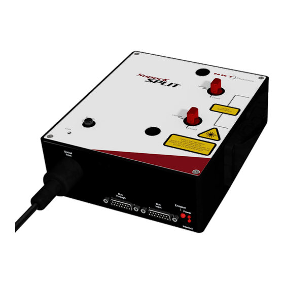
Description A SuperK SPLIT is a passive filter accessory for SuperK lasers. It divides the super continuum spectral emission from a SuperK laser into two separate wavelength ranges emitted from separate optical output ports. Each output emits a broadband subset of the original super continuum beam source. -
Page 14: Features
Shutters As a safety feature, each optical output of the SuperK SPLIT is equipped with a mechanical shutter. When the shutter is closed, it blocks all optical emission. The shutters are manually operated by turning the shutter knob between the... -
Page 15: Interfaces
Interfaces Interfaces Top panel The top panel shown in Figure 4 includes the following: • Input and output aperture indicators • Output shutter control knobs • Collimator release button with locking screw • Mounting hole access Figure 4 Top panel Mounting holes 5 Collimator locking screw NIR/IR output shutter... -
Page 16: Optical Apertures
Interfaces Mounting holes The two mounting holes (1) are designed to fasten the SuperK SPLIT to either metric or imperial optical tables that have screw holes spaced at either a 25 mm or a 1” pitch. NIR/IR output shutter This shutter can be set to block or unblock the NIR/IR emission output aperture. -
Page 17: Electrical Interfaces
Interfaces Optical input aperture The Optical input aperture is a receptacle that houses the output collimator of a SuperK laser. The laser’s output collimator is inserted into the aperture until it clicks and locks in place. To remove the collimator, press the release button. The laser’s collimator barrel can be secured by tightening the lock screw. -
Page 18: Status Leds
Status LEDs Optical input aperture “Optical input aperture” on page Bus through port Connects additional accessories to the External bus in a daisy chain configuration. A bus defeater is connected to this port if no other accessories are used with the SuperK laser. When no bus defeater is placed at the end of the External bus daisy chain, the interlock loop circuit is left open and emission disabled at the SuperK laser. -
Page 19: Table 1 Status Leds
Status LEDs Table 1 Status LEDs LED Name Condition Description Emission ON RED Emission enabled The SuperK laser system emission is ON and class 4 emission is present at the primary and auxiliary optical output ports. The position of the mechanical shutters at each output port does not change the status of the emission LED. -
Page 20: Chassis Labels
Status LEDs Chassis labels The SuperK SPLIT chassis includes multiple labels that indicate hazards and safety and product information. The labels are located on the panels as described in Table 2 with the panels shown in Figure 8 Figure Table 2 Chassis labels... -
Page 21: Figure 9 Top Panel Labels
Status LEDs Figure 9 Top panel labels 3. Class 4 Laser Radiation Warning Laser Aperture Laser Radiation Warning NOTE: Laser apertures are located on the side panel below the label. < 21 >... - Page 22 Status LEDs < 22 >...
-
Page 23: Installation
The SuperK SPLIT is intended for use with a SuperK Class 3B and 4 AUTION laser system only. Using the SuperK SPLIT with a laser source other than a Su- < 23 >... -
Page 24: Optical Connections
1. Disconnect power from the laser. 2. If not already installed, position the SuperK SPLIT at its final operating location and securing it to a suitable mounting surface. 3. Partially insert the laser’s output collimator barrel into the Optical Input... -
Page 25: Figure 11: Collimator Alignment Key And Slot
Electrical Connections When the key is aligned with the slot, the axial orientation of the collimator is correctly aligned. 5. Push the collimator into the receptacle until its collar rests against the chassis. As you push it in, the collimator encounters some resistance, and two distinct clicks as it locks in place. -
Page 26: Electrical Connections
Figures 14 and 15. Figure 14 Bus defeater If you do not terminate the External bus with an NKT Photonics bus de- feater, the interlock circuit remains open and laser emission cannot be enabled. Adding additional 1. If any additional accessories are to be connected to the SuperK laser, use... -
Page 27: Figure 13: Connecting The External Bus - Superk Laser
Electrical Connections 2. The last accessory of an External bus daisy chain requires the Bus Defeater to be placed on its Bus Through connector. To enable emission on a SuperK laser, the power supply and the door- switch interlock must be connected. For more information, refer to the instruction manual for the SuperK laser system. - Page 28 Electrical Connections < 28 >...
-
Page 29: Specifications
Specifications Table 3 Optical Model VIS/NIR output NIR/IR output A102-200-000 400-830 nm 915-2400 nm A102-500-000 400-1120 nm 1180-2400 nm Table 4 Interfaces All Chassis Models DB-15 Female Bus input Bus through DB-15 Female Table 5 Mechanical dimensions Specification 68 x 195 x 170 mm (2.68 x 7.68 x 6.70 in) Size (H x W x D) Weight ~4 kg (~8.8 lb) -
Page 30: Figure 16 Mechanical Dimensions
Figure 16 Mechanical dimensions < 30 >... -
Page 31: Service And Support Information
Figure 17 Warranty seal WARRANTY VOID IF SEAL IS BROKEN OR REMOVED Support Contact Details For technical or general support, NKT Photonics can be contacted for help regarding issues and questions with your accessory. Online Support Web- 1. Go to: page https://www.nktphotonics.com/support/... - Page 32 Support Contact Details Shipping Address NKT Photonics A/S Blokken 84 DK-3460 Birkerød Denmark < 32 >...
- Page 34 Blokken 84, Birkerød-3460 Denmark The information in this publication is subject to change without notice. All company and product names mentioned within are either trademarks or registered trademarks of NKT Photonics. Specifications are listed as metric units. Imperial units listed are conversions.
Need help?
Do you have a question about the SuperK SPLIT and is the answer not in the manual?
Questions and answers