Sign In
Upload
Manuals
Brands
NKT Photonics Manuals
Water Filtration Systems
A901-100-000
NKT Photonics A901-100-000 Manuals
Manuals and User Guides for NKT Photonics A901-100-000. We have
1
NKT Photonics A901-100-000 manual available for free PDF download: Product Manual
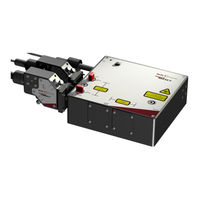
NKT Photonics A901-100-000 Product Manual (77 pages)
Multi Channel Tunable Filter
Brand:
NKT Photonics
| Category:
Water Filtration Systems
| Size: 14.23 MB
Table of Contents
Guide Overview
3
Documentation
3
Terminology
3
Table of Contents
5
Tables
9
Figures
11
Procedures
13
Description
15
AOTF Technology
15
Figure 1 Superk SELECT with Dual AOTF Outputs - General View
15
AOTF Crystal Types
16
Table 1 AOTF Crystal Models - Wavelength Bands (Nanometers)
16
RF Driver
17
Figure 2 Superk SELECT Standard Dual RF Driver System View
17
Features
18
Output
18
Interlock
18
Shutters
18
Power Lock (Optional)
18
Figure 3 Primary Output Shutters - VIR/NIR Set Open and NIR/IR Set Closed
18
Interfaces
19
Top Panel
19
Figure 4 Top Panel
19
Optical Apertures
21
Figure 5 Optical Interfaces
21
Monitor Ports
22
Figure 6 Optical Interfaces
22
Electrical Interfaces
23
Figure 7 Electrical Interfaces Ad Optical Input
23
External RF Driver
24
Figure 8 External RF Driver Unit - General View
24
ERD - Rear Panel
25
Figure 9 External RF Driver - Rear Panel
25
Superk SELECT Control
26
Software Description
26
Status Leds
26
Table 2 SELECT Status Leds
27
Figure 10 SELECT Status Leds
27
Chassis Labels
28
Table 3 Chassis Labels
28
Figure 11 Side Panel Manufacturing Label
28
Figure 12 Top Panel Labels
29
Installation
31
Installation Process
31
General
31
Optical Connections
32
Inserting the Superk Collimator
32
Figure 13 Partially Inserting the Collimator
32
Figure 14 Collimator Alignment Key and Slot
32
Procedure 1 Inserting a Superk Output Collimator
32
Optical Output
33
Electrical Connections
33
Single ERD System
33
Figure 15 Collimator Lock Screw
33
Procedure 2 Electrical Connections for a SELECT with a Single ERD
33
Figure 16 Connecting a SELECT - Single ERD
34
Figure 17 Connecting Single Erds
34
Figure 18 Bus Defeater
34
Dual ERD System
35
Figure 19 Setting External Bus Addresses - Single ERD System
35
Procedure 3 Electrical Connections for a SELECT with Dual Erds
35
Figure 20 Connecting a SELECT - Dual ERD
36
Figure 21 Connecting Dual Erds
36
Adding Additional Accessories
37
Figure 22 Setting External Bus Addresses - Dual ERD System
37
Procedure 4 Connecting Additional Accessories
37
Output Power Considerations
39
Output Beam Quality
39
Free Space Delivery
39
Fiber Delivery
39
Figure 23 Spectral Output of a Single AOTF Channel
39
Optimum RF Power
40
RF Power
40
Fiber Coupled
40
Figure 24 AOTF Transmission Spectrum for Varying RF Powers
40
Optimum RF Power Level
41
Remapping the Optimum RF Level
41
Figure 25 Optical Power for a Specific Wavelength as a Function of RF Power
41
Figure 26 Wavelength Versus Optimum RF Power Level
41
Beam Walk-Off
42
Reduction in Output Power
42
Realignment
42
Procedure 5 Remapping the Optimum RF Power Level
42
Using CONTROL
43
CONTROL Overview
43
Figure 27 CONTROL Panel Navigation
43
Device Selector
44
Address Selector
44
Figure 28 Device Selector Icon
44
Figure 29 Device Selector
44
Figure 30 Device Selector Set to 0Xe Bus Address
44
Status Panel
45
Status Indicators
45
Figure 31 Status Panel
45
System Info
46
RF Power Button
46
Emission Button
46
Control Settings
47
Figure 32 CONTROL Settings
47
Figure 33 Setup Menu Page
47
Control Panel
49
Normal Operating Mode
49
Figure 34 CONTROL Settings
49
Figure 35 Channel Controls - General Operation
50
Figure 36 Set Button Sliders
51
Figure 37 Band Views Per Output Channel (Crystal)
51
Figure 38 VIS/NIR Output with All Channels on
52
Figure 39 NIR/IR Output with All Channels on
52
Fast Wavelength Switching Mode
53
Figure 40 Dragging Channels in the Band View
53
Wavelength Sweep Mode
54
Figure 41 Fast Wavelength Switching Mode
54
Figure 42 Wavelength Sweep
55
A Specifications
57
Table 4 Optical
57
Table 5 Interfaces
57
Table 6 Mechanical Dimensions
57
Table 7 Electrical Specifications - External RF Drivers
57
Table 8 Operating and Storage Environment
58
Table 9 Safety and Regulatory Compliances
58
Figure 43 Mechanical Dimensions - Select Module
58
Figure 44 Mechanical Dimensions - External RF Driver
59
B Service and Support Information
61
Servicing
61
Opening the Chassis
61
WARRANTY VOID if REMOVED Label
61
Support Contact Details
61
Support Email
61
Online Support Web-Page
61
Shipping Address
61
Figure 45 Warranty Seal
61
C CONTROL Software
63
Installing CONTROL
63
Procedure 6 Installing CONTROL
63
D Using a Superk COMMAND Module
69
Description
69
Figure 46 COMMAND Electrical Connectors
69
Connect to a Superk SELECT System
70
Figure 47 Connecting a COMMAND Module
70
External Signal Requirements
71
Signaling and CONTROL Configuration
71
Or 4-Channel FWS
71
Table 10 COMMAND Input Specifications
71
Table 11 2 or 4 Channel FWS Truth Table
71
Procedure 7 Setting up 2 or 4 Channel Fast Wavelength Switching
71
Four 8-Channel Profile Switching
72
Table 12 4 Profile FWS Truth Table
72
Figure 48 Fast Wavelength Switching: 2 or 4 Λ Setup
72
Figure 49 Fast Wavelength Switching: 4 Profile Setup
73
Procedure 8 Setting up Four 8-Channel Profile Switching
73
16-Channel FWS
74
Table 13 16-Channel FWS Truth Table
74
Procedure 9 Setting up 16-Channel Fast Wavelength Switching
74
Figure 50 Fast Wavelength Switching: 16 Λ Setup
75
Modulating Emission Power
76
Figure 51 Fast Wavelength Switching: Simulated Modulated 4 Λ Setup
76
Advertisement
Advertisement
Related Products
NKT Photonics A203-000-001
NKT Photonics A301-100-000
NKT Photonics A102-200-000
NKT Photonics A102-500-000
NKT Photonics ADJUSTIK
NKT Photonics ADJUSTIK HP
NKT Photonics SuperK COMMAND
NKT Photonics SuperK CONNECT
NKT Photonics SuperK External RF Driver
NKT Photonics SUPERK SELECT
NKT Photonics Categories
Measuring Instruments
Water Filtration Systems
Amplifier
Industrial Electrical
Control Unit
More NKT Photonics Manuals
Login
Sign In
OR
Sign in with Facebook
Sign in with Google
Upload manual
Upload from disk
Upload from URL