
Related Manuals for NKT Photonics SuperK CONNECT


Summary of Contents for NKT Photonics SuperK CONNECT
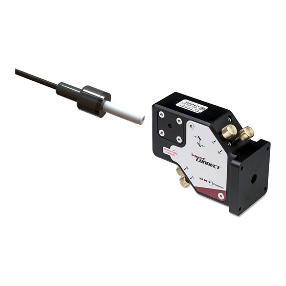
- Page 1 SuperK CONNECT and Fiber Delivery System Emission beam to fiber interface PRODUCT GUIDE Item 800-630-01...
- Page 2 PRODUCT GUIDE This guide applies to the following NKT Photonics products: CONNECT connection and alignment block (VIS or IR) Emission path adapter with alignment screws Item number: A401-X00-000 FDS standard fiber FD1-FD6, or FD10 w/ FC/APC or FC/PC connector Collimator to fiber to FC/APC or FC/PC connector...
-
Page 3: Guide Overview
NKT Photonics products including this accessory. Terminology The guide may refer to the SuperK CONNECT as just the CONNECT and a Fiber Delivery collimator with fiber may be referred to as an FD. Both the CONNECT and Fiber Delivery together are referred to as the Fiber Delivery System or FDS. - Page 4 • Appendices — Includes specifications and support contact details. Added information Lasers with their accessories are highly dangerous devices that can cause serious injury and property damage. This guide use the following symbols to and Safety Notices either highlight important safety information or provide further information in relation to a specific topic.
-
Page 5: Table Of Contents
Armored cable ..................15 Safety labels ................... 16 2 Installation ..................... 17 Mounting the CONNECT ................ 17 VIS or IR SuperK CONNECT orientation ........... 17 3 Optical Alignment ..................21 Aligning the FDS..................21 Tools list ..................... 21 Pre-alignment ..................21 Coarse alignment ................... - Page 6 Pinhole sliding ..................27 Weak power level ................28 No power measured at start of fine alignment ........29 4 Notes on Fiber Delivery ................31 Selecting standard or photonic crystal fiber delivery ......31 Wavelength transmission ..............31 Connectors and mating fiber light guides ..........31 Output coupling ..................
-
Page 7: Tables
TABLES Table 1: Fiber delivery models - single mode cut off ........... 14 Table 2: FD Fiber wavelength and transmission characteristics ......35... -
Page 9: Figures
Figure 5: Fiber spectral range and FD type label ............16 Figure 6: Input coupler: input power warning label ............ 16 Figure 7: SuperK CONNECT mounting orientations – visible port ......18 Figure 8: Fiber delivery unit – input coupler to FC/APC output ......18 Figure 9: Aligning the coupler key .................. -
Page 11: Procedures
PROCEDURES Procedure 1: Mounting a SuperK CONNECT to an optical output port....17 Procedure 2: Installing an FD module................18 Procedure 3: Pre-alignment....................21 Procedure 4: Coarse alignment..................23 Procedure 5: Fine Alignment of the assembled Fiber Delivery System....25 Procedure 6: Obtaining the optimum beam pattern and/or power ....... -
Page 13: Description
Table Note: A SuperK CONNECT of an FDS is specified for either IR or VIS wavelength bands. Note: When using an FDS mounted to an exit aperture, it is important to properly mount the SuperK CONNECT to the device before enabling emission from the la- ser system. -
Page 14: Fd Fiber Characteristics
Features Table 1 Fiber delivery models - single mode cut off Exit connector Fiber type Standard fiber FC/APC Standard fiber FC/PC Standard PM fiber FC/APC Standard PM fiber FC/PC Standard fiber Collimator Standard PM fiber Collimator FC/APC fiber LMA fiber FC/PC LMA PM fiber FC/APC... -
Page 15: Horizontal And Vertical Mounting
Pin-hole pupil approx. location Alignment tube beveled end Horizontal and The SuperK CONNECT can be mounted either horizontally or vertically onto a vertical mounting device output aperture, see “VIS or IR SuperK CONNECT orientation” on page Reversible coupler The input coupler of an FD is inserted into the CONNECT output port and clicks in place against a spring-loaded holder. -
Page 16: Safety Labels
Features Safety labels An SuperK Fiber Delivery (FD) system includes labels that indicate hazards and safety and product information. An FD includes the following labels types: • Input power level warning • FD type and wavelength coverage • Laser aperture labels with serial number on backside Laser Aperture A laser aperture label is tagged on the fiber cable. -
Page 17: Installation
The input power to the fiber delivery system (FDS) should always be lim- ited to below 500 mW. Note: Ensure to select the correct SuperK CONNECT model (VIS or IR) that match- es with your accessory output port. To mount a SuperK CONNECT to a laser accessory, follow the steps in Procedure 1 below. -
Page 18: Figure 7 Superk Connect Mounting Orientations - Visible Port
2. Insert the FD coupler into the CONNECT output port until its collar is flush against the SuperK CONNECT. To insert the coupler completely, the key on the collar of the coupler must be aligned with the slot on the CONNECT... -
Page 19: Figure 9 Aligning The Coupler Key
Lock screw Note: The lock screw may be mounted on either side of the SuperK CONNECT. If you cannot access the screw, unfasten and remove the lock screw assembly and install it on the opposite side of the CONNECT. You may need to remove the CON- NECT from its mounting location to gain access. - Page 20 Mounting the CONNECT...
-
Page 21: Optical Alignment
Warning: The SuperK CONNECT together with a SuperK laser system constitutes a class 4 laser source and must be regarded as a potential hazard to the operator. Make sure to wear laser protective eyewear when operating the SuperK CON- NECT and when aligning its optical output. -
Page 22: Coarse Alignment
(If the accessory allows it, set the laser to a green color for best visual sensitivity.) 3. Open the aperture shutter (if equipped) on the device the SuperK CONNECT is mounted to. -
Page 23: Figure 12 Coarse Alignment - Alignment Tool Inserted
“Tips for steering the beam path” on page 26 tips on how to adjust the beam path. Disable the laser emission and insert the alignment tool, with the beveled-end inserted half-way into the output port of the SuperK CONNECT. Note: Insert the alignment tool gently. -
Page 24: Fine Alignment Of The Fds
Fine alignment of the FDS Figure 13 Coarse alignment - spot adjustment Beam target Beveled end - inserted Pin-hole Main beam spot centered in its halo 6. Disable emission. 7. Remove the alignment tool from the CONNECT and reinstall it in the reverse direction. -
Page 25: Procedure 5 Fine Alignment Of The Assembled Fiber Delivery System
10. Repeat step 8 adjusting the thumbscrew pairs iteratively until the optimum alignment has been achieved when no further power increase can be realized. 11. The SuperK CONNECT is now aligned with the FD. Note: When using a power meter to measure the light from the FD connector, it is recommended to use a sensor with a fast response time. -
Page 26: Tips For Steering The Beam Path
Tips for steering the beam path Figure 14 Fine alignment - power measurement FD output FD input coupler inserted Lock screw 00.23 Power meter Tips for steering the beam path This section includes information on beam path adjustment using the CONNECT and certain conditions that can result in weak or no output power from the FDS. -
Page 27: Pinhole Sliding
Tips for steering the beam path Figure 15 Alignment screw pair markings Top panel Pair “I” Output mirror thumbscrews Output longitudinal axis Pair “II” Input longitudinal axis Pair “II” Input mirror thumbscrews Pair “I” Procedure 6 Obtaining the optimum beam pattern and/or power With the beam output being monitored, turn either the I or II output mirror thumbscrews an eighth to a half turn to improve the beam pattern or power. -
Page 28: Weak Power Level
Tips for steering the beam path out, tightens (improves) the accuracy of the alignment spot. This is because, the pin hole physically limits the angle of acceptance, which decreases the further the pinhole is away from the mirror - see Figure 16 below. -
Page 29: No Power Measured At Start Of Fine Alignment
Tips for steering the beam path Figure 17 Side lobe vs main peak fiber coupling PCF fiber Output lateral axis Beam wavefront Beam wavefront misaligned aligned OOB side lobe Main peak Recovering the main peak If you suspect a side lobe has been coupled, then follow the steps in the coarse alignment procedure. - Page 30 Tips for steering the beam path Cause In certain cases, the beam maybe be centered from the CONNECT output, but the centering of the fiber facet is mounted slightly out of positional tolerance within the input coupler. In these cases, you must use the thumbscrews to move the beam slightly, positioning the beam onto the fiber facet.
-
Page 31: Notes On Fiber Delivery
Notes on Fiber Delivery NKT Photonics can supply multiple Fiber Delivery types which can be characterized by their fiber and connector types. This chapter includes information discussing fiber types, coupler and collimator keying, mating fibers, cleaning fiber facets and protecting them from contaminants. -
Page 32: Pm Fibers And Keying
PM Fibers and keying diverging field. The wide divergence means that a standard butt joint cannot be used with subsequent fiber delivery systems due to the coupling loss. Therefore PCF is only suitable when the FD is fitted with an output collimator which can adequately refocus the light with its achromatic lens. -
Page 33: Cleaning Of Fiber Facets
Fiber and connector care Cleaning of fiber facets The fiber connector on the FD may occasionally require some cleaning of the fiber tip. Before making any fiber connections, always inspect the fiber facet of all connectors using an inspection scope. A scope with both coaxial and oblique illumination is useful in exposing any contaminants or defects in the facet. - Page 34 Fiber and connector care...
-
Page 35: A Specifications
Specifications Table 2 FD Fiber wavelength and transmission characteristics FD fiber type Cut-off λ % Transmission Typical peak % transmission FD1-PM 425±25 nm > 60% from 425 to 775 nm 75% @ 650 nm 450±25 nm > 60% from 450 to 775 nm 80% @ 650 nm 630±20 nm >... -
Page 37: B Service And Support Information
Service and Support Information Servicing The accessory has no user serviceable components. In case of malfunction, contact NKT Photonics using the support channels in section “The unit is sealed with a label “WARRANTY VOID IF REMOVED”. It is strictly prohibited to remove the chassis cover”. -
Page 38: Support Contact Details
Servicing Support contact details If you need help or have questions regarding your SuperK CONNECT and/or FD, contact NKT Photonics through our support website below: Support website 1. Go to: https://www.nktphotonics.com/lasers-fibers/support/technical-support-and- customer-service/ 2. Scroll down and click or press: 3. Select the help type, fill in the form, and click or press Submit. - Page 40 SuperK Fiber Delivery System Product Description Revision 1.0 08-2021 W-10456...
Need help?
Do you have a question about the SuperK CONNECT and is the answer not in the manual?
Questions and answers