Table of Contents
Advertisement
Quick Links
Advertisement
Table of Contents

Related Manuals for NKT Photonics SuperK SELECT


Summary of Contents for NKT Photonics SuperK SELECT
- Page 1 800-614-01 SuperK SELECT Product Guide Revision 1.3 10-2023...
- Page 2 PRODUCT GUIDE This guide includes information for the following NKT Photonics products: SuperK SELECT Multi Channel Tunable Filter Item number: A203-XXX-XXX SuperK External RF Driver RF Signal Generator Item number: A901-100-000 SuperK COMMAND Fast Wavelength Switching Signaling Interface Item number: A203-000-001 Do not open the device chassis.
-
Page 3: Guide Overview
The paper copy of this guide is included with your accessory; it can also be downloaded from: https://www.nktphotonics.com/product-manuals-and-documentation/ Terminology The guide may refer to the SuperK SELECT as the SELECT, device or accessory. Target Audience This guide is for technical personnel involved in the selection, planning and deployment of lasers and photonic equipment in laboratory and industrial settings. - Page 4 Highlights additional information related to the associated topic and/or provides links or the name of the NKTP guides describing the additional infor- mation. Alerts you to a potential hazard that could cause loss of data, or dam- AUTION age the system or equipment. The laser safety warning alerts you to potential serious injury that ARNING may be caused when using a laser with the accessory.
-
Page 5: Table Of Contents
Optical apertures ......................21 Monitor ports ........................22 Electrical Interfaces ......................23 External RF driver ........................ 24 ERD - rear panel ......................25 SuperK SELECT Control...................... 26 Software Description ...................... 26 Status LEDs ......................... 27 Chassis labels ........................28 Installation ........................31 Installation process ...................... - Page 6 Inserting the SuperK collimator ..................32 Optical output ......................... 33 Electrical Connections ......................33 Single ERD system ......................33 Dual ERD system ......................35 Adding additional accessories ..................37 Output Power Considerations ..................39 Output beam quality......................39 Free space delivery ......................39 Fiber Delivery .........................
- Page 7 CONTROL Software...................... 63 Installing CONTROL ......................63 Using a SuperK COMMAND module................69 Description ........................... 69 Connect to a SuperK SELECT system ................70 External signal requirements ..................71 Signaling and CONTROL configuration ................71 2 or 4-channel FWS ....................... 71 Four 8-channel profile switching ..................
- Page 8 < 8 >...
-
Page 9: Tables
TABLES Table 1: AOTF crystal models – wavelength bands (nanometers) ..........16 Table 2: SELECT Status LEDs ....................27 Table 3: Chassis labels....................... 28 Table 4: Chassis labels....................... 28 Table 5: Optical ........................57 Table 6: Interfaces ........................57 Table 7: Mechanical dimensions....................57 Table 8: Electrical specifications –... - Page 10 < 10 >...
-
Page 11: Figures
FIGURES Figure 1: SuperK SELECT with dual AOTF outputs – general view ........... 15 Figure 2: SuperK SELECT standard dual RF driver system view..........17 Figure 3: Optical output shutters – VIR/NIR set open and NIR/IR set closed ......18 Figure 4: Top panel........................ - Page 12 Figure 35: Channel controls - general operation................. 50 Figure 36: ‘Set button sliders ...................... 51 Figure 37: Band views per output channel (crystal)..............51 Figure 38: VIS/NIR output with all channels ON ................. 52 Figure 39: NIR/IR output with all channels ON ................52 Figure 40: Dragging channels in the band view................
-
Page 13: Procedures
PROCEDURES Procedure 1: Inserting a SuperK output collimator ..............32 Procedure 2: Electrical connections for a SELECT with a single ERD ........33 Procedure 3: Electrical connections for a SELECT with dual ERDs .......... 35 Procedure 4: Connecting additional accessories ............... 37 Procedure 5: Remapping the optimum RF power level ............. - Page 14 < 14 >...
-
Page 15: Description
Description The SuperK SELECT is a plug & play filter accessory for the SuperK series of lasers. It can tune and select multiple wavelengths from the emission spectrum of a SuperK laser. The SELECT also includes a range of unique features which... -
Page 16: Aotf Crystal Types
AOTF crystal types The SELECT can be specified with a variety of AOTF crystals that filter wavelengths from the SuperK emission spectrum from 400 to 2000 nm. Table 1 lists the crystal models available and the combinations which can be fitted in a dual AOTF SELECT. -
Page 17: Rf Driver
RF driver An NKT Photonics External RF Driver (ERD) unit is connected to the SELECT’s RF1 input. A single ERD generates the necessary RF signals to drive a single AOTF crystal. The RF signals generated by the driver are configured to drive an AOTF for up to 8 output wavelengths. -
Page 18: Features
Connections” on page Shutters As a safety feature, each optical output of the SuperK SELECT is equipped with a mechanical shutter. When a shutter is closed, it blocks all optical emission. The shutters are manually operated by turning the shutter knob between the Open and... -
Page 19: Interfaces
Release button (6). When the collimator is inserted, use the nearby locking screw (5) to securely fasten it. Mounting holes The two mounting holes (2) are designed to fasten the SuperK SELECT to either metric or imperial optical tables that have screw holes spaced at either 25 mm or 1” pitch. - Page 20 This is an IR output where unused and unfiltered light from the input beam of the SuperK laser is emitted from the SELECT. The port is intended for use with for example, another SuperK SELECT operating at higher wavelengths. When not used, a cover plate is mounted on the aperture to block emission.
-
Page 21: Optical Apertures
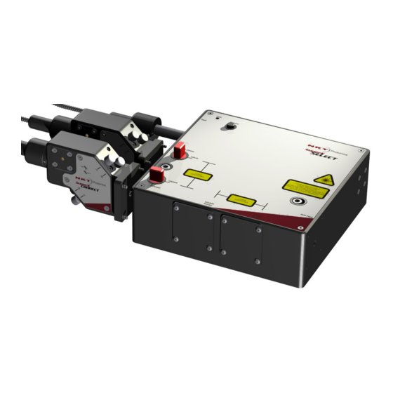
Interfaces Optical apertures Optical apertures are located on two of the side panels of the SELECT as shown Figure 5 and described in the following. Figure 5 Optical Interfaces Optical input aperture 3 VIS/NIR output aperture NIR/IR output aperture – with shipping 4 Monitor optical output apertures –... -
Page 22: Monitor Ports
Interfaces Monitor ports Monitor ports are located on the side panels of the SELECT as shown in Figure 5. The ports and connectors shown in the figure are optionally fitted with power monitors before leaving the factory. The power monitors receive a tiny fraction of the VIS/NIR and NIR/IR output beams. -
Page 23: Electrical Interfaces
Interfaces Electrical Interfaces Figure 7 shows the electrical interfaces located on a side panel of the SELECT. Figure 7 Electrical Interfaces ad optical input Monitor output 6 RF Power I LED Accessory bus address selector Bus through port (External bus output) RF Power II LED 8 Bus input port (External bus input) RF Power II input... -
Page 24: External Rf Driver
SuperK output spectrum. The ERD is connected to the External bus of the SuperK laser system and is managed using NKT Photonics CONTROL software. Based on the configuration in CONTROL and the AOTF calibration, the ERD transmits an appropriate RF signal to an AOTF crystal. -
Page 25: Erd - Rear Panel
External RF driver ERD - rear panel Figure 9 External RF Driver – rear panel Power/comms and interlock LEDs Address selector (external bus) Modulation connector Bus through port (external bus) PWM – reserved for future use Bus input (external bus) RF USB –... -
Page 26: Superk Select Control
SuperK SELECT Control AC mains input Standard C14 input connector for a C13 power cord. AC ON/OFF switch Toggles AC power on or off to the ERD. SuperK SELECT Control Software Description Both the SuperK laser and the SELECT accessory are controlled using NKT Photonic’s CONTROL management software installed on a PC or the front panel... -
Page 27: Status Leds
Status LEDs Status LEDs The SELECT includes three status LEDs as described in Table 2. The LEDs are located on a side panel next to the External bus input as shown in Figure The emission LED is lit ON RED when the connected SuperK laser’s emission is enabled. -
Page 28: Chassis Labels
Chassis labels Chassis labels The SuperK SELECT chassis includes multiple labels that indicate hazards and safety and product information. The labels are located on the panels as described in Table 4 with the panels shown in Figure 11 Figure Table 3 Chassis labels... -
Page 29: Figure 12 Top Panel Labels
Chassis labels Figure 12 Top panel labels Laser Apertures 3 Class 4 Laser Radiation Warning Laser Radiation Warning NOTE: Laser apertures are located on the side panel below the label. < 29 >... - Page 30 Chassis labels < 30 >...
-
Page 31: Installation
General All chassis types must be installed on a level surface that is free from vibrations. The SuperK SELECT can be fastened to both metric and imperial optical tables. The ambient temperature surrounding the laser and SELECT system should be stable and free from anything that could cause temperature fluctuations. -
Page 32: Optical Connections
The SuperK SELECT is intended for use with the SuperK Class 3B AUTION and 4 lasers systems only. Using the SuperK SELECT with a laser source other than a SuperK laser may result in hazardous radiation exposure. To operate these systems, you must be familiar with laser safety reg- ARNING ulations and have received instruction in the safe use of lasers. -
Page 33: Optical Output
2.5 mm hex key Inserted collimator Optical output All optical outputs are free space. NKT Photonics can provide SuperK CONNECT accessories and collimators as described in the document: SuperK CONNECT and Fiber Delivery Product Guide Electrical Connections For dual ERD systems – see “Dual ERD system”... -
Page 34: Figure 16 Connecting A Select - Single Erd
Electrical Connections 2. Using an External bus cable, connect the External bus connector of the SuperK laser to the Bus Input connector (item D of Figure 16) of the SELECT. Figure 16 Connecting a SELECT - single ERD NOTE: Connect a 50 Ω BNC ter- A: 50 Ω... -
Page 35: Dual Erd System
Electrical Connections To reduce RF leakage, connect a 50 Ω terminator to the unused RF port of the SELECT (see Figure 16 item A). 6. Set the address bus select switches to a unique address for the SELECT and ERD as shown in Figure All modules on the External bus must use a unique address. -
Page 36: Figure 20 Connecting A Select - Dual Erd
ERD (item E of Figure 21). Ensure to terminate the External bus with an NKT Photonics bus defeater, Without the bus defeater, the interlock circuit remains open disabling laser emis- sion. 6. Using an RF coaxial cable, connect the RF BNC port of the ERD 1 (item A of... -
Page 37: Adding Additional Accessories
Electrical Connections 7. Using the other RF coaxial cable, connect the RF BNC port of the ERD 2 (item B of Figure 21) to the RF 2 port of the SELECT (item A of Figure 20). 8. Set the bus address select switches to a unique address for the SELECT and each ERD as shown in Figure All modules on the External bus must use a unique address. - Page 38 Electrical Connections 2. Using an External bus cable, connect the Bus Through connector from the current last module to the External bus connection of the newly added accessory. 3. Repeat step 2 for each new accessory. 4. On last accessory module in the External bus daisy chain, connect the Bus Defeater on its Bus Through connector.
-
Page 39: Output Power Considerations
Fiber Delivery If a fiber delivery system is mounted to the outputs of the SuperK SELECT, the single mode coupling acts as a spatial filter. In this case, no aperture in the beam path is required. Side lobe suppression will depend on the numerical aperture of the delivery fiber. -
Page 40: Optimum Rf Power
The systems shipped from NKT Photonics A/S, have their optimum RF power mapped as a function of wavelength. Your SELECT system RF level is al- ready optimally mapped at the NKT Photonics factory and unless you swap-out certain hardware, no further optimization is required. -
Page 41: Optimum Rf Power Level
Optimum RF power the RF driver power reaches a level between 40 and 50 percent, no further output optical power is achieved by further increasing the RF driver power. Figure 25 Optical power for a specific wavelength as a function of RF power Optimum RF The optimum RF power depends on several factors, one of which is the selected wavelength. -
Page 42: Remapping The Optimum Rf Level
When power reduction is due to beam walk-off, realignment is necessary to restore the optimum coupling efficiency and thus output power. The FDS must be realigned using the procedures in the NKT Photonics document: SuperK Fiber Deliver System Product Guide... -
Page 43: Using Control
Figure 27 shows CONTROL’s main panels and menu; their functions are described in the table below. This chapter only describes CONTROL functions related to the SuperK SELECT, for all other functionality, refer to the specific SuperK documentation. Panel Function... -
Page 44: Device Selector
Device Selector Device Selector In the Device Selector panel, you can find icons of SuperK nodes that CONTROL is currently communicating with. To manage any device, click on its corresponding icon. When the icon is highlighted blue, its Control panel and Status panel are displayed. -
Page 45: Status Panel
Status Panel Only turn ON the SuperK laser and connected accessories after all con- AUTION nected accessories are configured with a unique address. Status Panel The Status Panel contains status indicators, error messages, an emission control button, and a CONTROL settings menu. Figure 31 Status Panel Settings drop-down menu Status indicators... -
Page 46: System Info
Status Panel NIR/IR output shutter Indicates the position of the mechanical shutter for the NIR/IR output shutter. The shutter is either in the closed or open position. • ON Green – the NIR/IR output shutter is in the open position, laser emission can pass through the aperture. -
Page 47: Emission Button
Status Panel Emission button The emission button enables or disables the SuperK laser emission. The button indicator turns ON Red when laser emissions are enabled. When disabled, the indicator is OFF Grey. This button is the same button available in the CONTROL status panel of the connected SuperK laser. - Page 48 Status Panel VIS/NIR RF power – or – NIR/IR RF power – Range: Normal or Overdrive In Normal mode, the power level in the main spectral peak increases as RF power is increased. Power coupling to a fiber deliver system is optimized when operating in this mode.
-
Page 49: Control Panel
Control panel VIS/NIR or NIR/IR modulation gain Range: 0-1 V, 0-5 V, 0-10 V When operating using Fast wavelength switching mode, the input modulation gain should match modulation input signal(s) connected to an optional SuperK COMMAND device. This setting allows you to choose between 3 different input voltage ranges for the Modulation inputs. -
Page 50: Figure 35 Channel Controls - General Operation
Control panel If the system is equipped with a single External RF Driver, only a single crystal or output is available for operation. You can select either AOTF using the Crystal selection drop down menu under Channels. Figure 35 Channel controls - general operation Select an AOTF crystal Operating mode drop down selection... -
Page 51: Figure 36 'Set Button Sliders
Control panel sliders with your mouse to set the power and center wavelength of the channel. To close the slider view, click the X in the upper right corner. Figure 36 ‘Set button sliders Band view The band view displays a visual representation of the range of light wavelengths available for a crystal. -
Page 52: Figure 38 Vis/Nir Output With All Channels On
Control panel When a channel is ON, it appears in the band view as shown in Figure 35. If all 8 channels are ON, 8 channels will appear in the band view as shown in Figure 38 Figure Figure 38 VIS/NIR output with all channels ON Buttons toggled to green indicate the channel is Enter the channel’s... -
Page 53: Fast Wavelength Switching Mode
Control panel Dragging channels Using your mouse, you can click-hold on a channel symbol and slide it within the band view, thereby adjusting the wavelength and power level – see Figure Figure 40 Dragging channels in the band view Click hold and drag the icon Release the mouse to set the new power... -
Page 54: Wavelength Sweep Mode
Control panel Figure 41 Fast wavelength switching mode Wavelength sweep The “Wavelength sweep” mode allows for a relatively slow wavelength sweep/ step function. You can set a range of wavelengths to step through and repeat mode < 54 >... -
Page 55: Figure 42 Wavelength Sweep
Control panel as long as the Sweep button is clicked ON. Figure 42 shows an example of a Wavelength sweep configuration with description below. Figure 42 Wavelength sweep Wavelength sweep example Figure 42, Wavelength sweep mode is set to perform the following sweep: •... - Page 56 Control panel < 56 >...
-
Page 57: A Specifications
Collimated free-space output, FWHM bandwidth. Horizontal with respect to base. Table 6 Interfaces All Chassis Models DB-15 Female External bus BNC (Optional - Custom feature, contact NKT Photonics) Monitor Table 7 Mechanical dimensions Specification Select Module External RF Driver 68 x 272 x 212 mm... -
Page 58: Table 9 Operating And Storage Environment
Table 9 Operating and storage environment Specification Select Module External RF Driver 18°C to 28°C 15°C to 37°C Operating Temperature -20°C to 50°C Storage Temperature 20 to 80% RH 20 to 80% RH Operating Humidity (non-condensing) 3000 m maximum Operating Altitude 700 hPa to 1060 hPa Operating Air Pressure Table 10 Safety and regulatory compliances... -
Page 59: Figure 44 Mechanical Dimensions - External Rf Driver
Figure 44 Mechanical dimensions – External RF Driver < 59 >... - Page 60 < 60 >...
-
Page 61: Service And Support Information
Figure 45 Warranty seal WARRANTY VOID IF SEAL IS BROKEN OR REMOVED Support Contact Details For technical or general support, NKT Photonics can be contacted for help regarding issues and questions with your accessory. Online Support Web- 1. Go to: page https://www.nktphotonics.com/support/... -
Page 62: Shipping Address
Support Contact Details Shipping Address NKT Photonics A/S Blokken 84 DK-3460 Birkerød Denmark < 62 >... -
Page 63: Control Software
CONTROL Software Installing CONTROL Download the software from: https://www.nktphotonics.com/support/ Follow the steps in Procedure Procedure 6 Installing CONTROL Action On the PC, launch the installer package and then click the Run button. Installer The installation wizard appears. Click Next to continue. Accept to use the default installation directory or select another directory by clicking the Browse button. - Page 64 Installing CONTROL Action Uncheck the components you do not require. By default, all components are installed. Click Next to continue. Read the End-User License Agreement, and check “I accept the license.” box. Not checking the box ends the installation wizard. Click Next to continue.
- Page 65 Installing CONTROL Action Check the box to create a desktop shortcut to access Control. Click Next to continue Check the ‘Run the Silicon Labs CP10x driver installation’ box and click Next. Note: If you do not have the driver installed USB connectivity will fail.
- Page 66 Installing CONTROL Action The wizard displays a progress meter for the installation. Note: a normal install should only take a few seconds. Click Next to install the UART drivers for the PC USB port. The drivers are installed. Note: Depending on your computer this occurs so fast you may not see this.
- Page 67 Installing CONTROL Action The Silicon Labs drivers is installed successfully. Click Finish to end the driver installation. CONTROL is now installed. Check the Run box to launch CONTROL when the Finish button is clicked. Click Finish to end the installation wizard. <...
- Page 68 Installing CONTROL < 68 >...
-
Page 69: Using A Superk Command Module
These signals are then used to drive and synchronize fast wavelength switching and amplitude modulation of the output beam from an AOTF crystal of a SuperK SELECT system. When using a COMMAND module, the system can achieve wavelength switching based on external signal input at speeds down to 10 microseconds. -
Page 70: Connect To A Superk Select System
Description Truth tables When using a COMMAND module with the SELECT, wavelength or profile selection is based on truth table results from a combination of the input signals. The result determines the wavelength of a channel or entire profile as configured in CONTROL. -
Page 71: External Signal Requirements
Signaling and CONTROL configuration External signal Electrical specifications for the COMMAND inputs are shown in requirements Table 11 COMMAND input specifications Value Comment FSK1 to FSK8 0-3.3 V or TTL MOD1 to MOD8 0-1 V, 0-5 V, 0-10 V Configured in CONTROL BLANK 0-3.3 V or TTL Signaling and CONTROL configuration... -
Page 72: Four 8-Channel Profile Switching
Signaling and CONTROL configuration 5. Set the power level desired in one of the profile channels. This sets the power level to be identical for all configured channels in each profile. 6. Using a BNC cable, connect the MOD1 pin to the +3.3 V output pin on the COMMAND. - Page 73 Signaling and CONTROL configuration High Profile 3 Channels 1 to 8 High High Profile 4 Channels 1 to 8 Procedure 8 Setting up four 8-channel profile switching 1. In CONTROL, click on the SELECT device icon and ensure the mode is set to Fast Wavelength Switching.
-
Page 74: 16-Channel Fws
Signaling and CONTROL configuration Figure 49 Fast wavelength switching: 4 profile setup CONTROL Channel/Profile Wavelengths 1 to 4 Selection ch1 to 8/p1 ch1 to 8/p1 ch1 to 8 - profile 1 MOD1 ch1 to 8 - profile 2 Test Blank Outputs ch1 to 8 - profile 3 ch1 to 8 - profile 4... - Page 75 Signaling and CONTROL configuration High High Profile 4 Channel 4 High High Profile 4 Channel 5 High High Profile 4 Channel 6 High High Profile 4 Channel 7 High High Profile 4 Channel 8 You can also configure 16 wavelengths using profiles 1 and 3; however, the logic of the signaling required for wavelength selection is reversed at the COM- MAND module.
-
Page 76: Figure 50 Fast Wavelength Switching: 16 Λ Setup
Signaling and CONTROL configuration Figure 50 Fast wavelength switching: 16 λ setup Application signals Channel selected ch8 profile 4 ch7 profile 4 ch6 profile 4 ch5 profile 4 ch4 profile 4 ch3 profile 4 CONTROL Channel/Profile ch2 profile 4 ch1 profile 4 Profile 2 ch8 profile 2 ch7 profile 2... -
Page 77: Modulating Emission Power
Signaling and CONTROL configuration Modulating emission To modulate the amplitude of selected channels, a modulating signal can be power connected to the MOD1-8 signals (i.e. instead of them being pulled high). For four-channel or four-profile FWS configurations only MOD1 is connected to a varying signal to modulate the channels. - Page 78 Signaling and CONTROL configuration < 78 >...
- Page 80 Blokken 84, Birkerød-3460 Denmark The information in this publication is subject to change without notice. All company and product names mentioned within are either trademarks or registered trademarks of NKT Photonics. Specifications are listed as metric units. Imperial units listed are conversions.
Need help?
Do you have a question about the SuperK SELECT and is the answer not in the manual?
Questions and answers