
Subscribe to Our Youtube Channel
Related Manuals for GRASS VALLEY MV-8 Series


Summary of Contents for GRASS VALLEY MV-8 Series
- Page 1 MV-825-RTR MULTIVIEWER WITH INTEGRATED ROUTER User Manual MV-825-RTRUM 01 Dec 2020, Issue 1 Revision 1...
-
Page 2: Fcc Compliance
Valley USA, LLC, or one of its affiliates or subsidiaries. All other intellectual property rights are owned by GVBB Holdings SARL, Grass Valley USA, LLC, or one of its affiliates or subsidiaries. All third party intellectual property rights (including logos or icons) remain the property of their respective owners. -
Page 3: Read Me First
Thank you for purchasing your new MV-825-RTR product from Grass Valley. The MV-825-RTR contains a video router and a powerful multiviewer. When using the MV-825-RTR you will need access to the following Grass Valley documents, available from the Grass Valley website: 1 MV-825-RTR Multiviewer with Integrated Router User Manual (i.e. - Page 4 The presence of this symbol in or on Grass Valley equipment means that it has been tested and certified as complying with applicable Underwriters Laboratory (UL) regulations and recommendations for USA.
- Page 5 MV-825-RTR User Manual The presence of this symbol in or on Grass Valley equipment means that it has been tested and certified as complying with applicable Intertek Testing Services regulations and recommendations for USA/Canada. The presence of this symbol in or on Grass Valley product means that it complies with all applicable European Union (CE) directives.
- Page 6 Replace the battery only with the same or equivalent type recommended by the manufacturer. Dispose of used batteries according to the manufacturer’s instructions. Before disposing of your Grass Valley equipment, please review the Disposal and Recycling Information at: http://www.grassvalley.com/assets/media/5692/Take-Back_Instructions.pdf...
- Page 7 MV-825-RTR User Manual Mesures de sécurité et avis importants La présente section fournit des consignes de sécurité importantes pour les opérateurs et le personnel de service. Des avertissements ou mises en garde spécifiques figurent dans le manuel, dans les sections où ils s’appliquent. Prenez le temps de bien lire les consignes et assurez-vous de les respecter, en particulier celles qui sont destinées à...
- Page 8 électrique, de compatibilité électromagnétique et de conformité environnementale. Le symbole ci-contre sur un appareil Grass Valley ou à l’intérieur de l’appareil indique qu’il est conforme aux normes applicables en matière de sécurité laser. Avertissements Les avertissements signalent des conditions ou des pratiques susceptibles d’occasionner des blessures graves, voire fatales.
- Page 9 MV-825-RTR User Manual • Ne pas utiliser cet appareil dans une atmosphère explosive. • Présence possible de courants de fuite. Un raccordement à la masse est indispensable avant la mise sous tension. • Après tout travail d’entretien ou de réparation, faites effectuer des contrôles de sécurité par le personnel technique qualifié.
- Page 10 équivalent recommandé par le fabricant. Disposez des piles usagées conformément aux instructions du fabricant. Avant de vous séparer de votre équipement Grass Valley, veuillez consulter les informations de mise au rebut et de recyclage à: http://www.grassvalley.com/assets/media/5692/Take-Back_Instructions.pdf Précautions pour les écrans LCD et TFT Regarder l’écran pendant une trop longue période de temps peut nuire à...
- Page 11 Grass Valley believes this environmental information to be correct but cannot guarantee its completeness or accuracy since it is based on data received from sources outside our company. All specifications are subject to change without notice.
-
Page 12: Further Safety Information
Lithium Batteries Battery Warning Your Grass Valley equipment usually comes with at least one button battery located on the main printed circuit board. The batteries are used for backup and should not need to be replaced during the lifetime of the equipment. - Page 13 MV-825-RTR User Manual Laser Safety The MV-825-RTR unit has ‘small form-factor’ module cages at its rear for SFP (small form- factor pluggable) plug-in modules. Various SFP optical fiber modules may be fitted into some rear cages. Laser Safety - Fiber Output SFP Modules Warning LASER SAFETY The average optical output power does not exceed 0 dBm (1mW) under normal operating conditions.
- Page 14 Notices Equipment Mains Supply Voltage Before connecting the equipment, observe the safety warnings section and ensure that the local mains supply is within the rating stated on the rear of the equipment. Mains supply rating for the equipment. Rear Mains Inlets and Mains Supply Rating Power Cords Supplied WARNING To reduce the risk of electric shock, plug each power supply cord into...
-
Page 15: Safety And Emc Standards
MV-825-RTR User Manual Safety and EMC Standards This equipment complies with the following standards: Safety Standards Information Technology Equipment - Safety Part 1 EN60950-1: 2006 Safety of Information Technology Equipment Including Electrical Business Equipment. UL1419 (4 Edition) Standard for Safety – Professional Video and Audio equipment (UL file number E193966) EMC Standards This unit conforms to the following standards: EN55032:2015 (Class A) - Page 16 EMC Performance of Cables and Connectors Grass Valley products are designed to meet or exceed the requirements of the appropriate European EMC standards. In order to achieve this performance in real installations it is essential to use cables and connectors with good EMC characteristics.
-
Page 17: Document History
MV-825-RTR Multiviewer with Integrated Router User Manual Document History Publication Document Document Notes Date Part Number Issue and Revision 1-Dec-2020 MV-825-RTRUM Issue 1 Revision 1 First issue. xvii... - Page 18 Document History xviii...
-
Page 19: Table Of Contents
Table of Contents FCC Compliance ..............ii Patent Information . - Page 20 Table of Contents Multiviewer Head Display Outputs..........27 Rear Connectors - Aux Inputs/Outputs .
- Page 21 MV-825-RTR Multiviewer with Integrated Router User Manual Comms Setup - Restart Unit ............84 Router - Log Fields Screen .
- Page 22 Table of Contents System Configuration Page ........... . .144 Apply Changes and Restart.
- Page 23 MV-825-RTR Multiviewer with Integrated Router User Manual Appendix A MV-825-RTR Specification ....189 Power ................189 Operating Environment .
- Page 24 Table of Contents xxiv...
-
Page 25: Product Overview
The Grass Valley MV-825-RTR is a compact and space-saving integrated router and multiviewer. It combines a 48x48 SDI video router and a powerful 48-in/12-out MV-8 Series multiviewer. Both the multiviewer and the router are optionally 12G SDI capable. An MV- 825-RTR can flexibly monitor 48 source SDI video signals and, independently, route them to 48 SDI outputs. -
Page 26: Features
• SNMP. • Monitor unit via SNMP. Internal Multiviewer: • MV-8 Series multiviewer core shared with other MV-8XX GV products. • Up to 48 video signals monitored (SD-SDI/ HD-SDI/ 3G-SDI/ UHD/ 12G-SDI). • Up to 12 multiviewer head display outputs: •... - Page 27 MV-825-RTR Multiviewer with Integrated Router User Manual • When designing video wall: • Drag and Drop objects onto the screen layout. • Adjust layering, transparencies and fine-positioning of graphical objects. Flexible alarm capability: • Monitoring of video, audio and metadata, with alarm notification. •...
-
Page 28: Order Codes
SFP Modules (SDI video): Per SFP module: • 2x SDI outputs (coaxial or fiber); or • 1x HDMI output. CC-TTH-3G-N Multiviewer HD-BNC Dual Output SFP module. Grass Valley module number SM-TT-3G. ST31ST31-3 Multiviewer Fiber Dual Output SFP module (1310 nm, single mode LC/PC). FC1-HDMI1 HDMI single output SFP module. -
Page 29: Mv-825-Rtr Architecture
MV-825-RTR Multiviewer with Integrated Router User Manual MV-825-RTR Architecture Inputs and Outputs Figure 1-2 shows the main input and output signals of a MV-825-RTR unit. Fig. 1-2: MV-825-RTR - Main Inputs and Outputs • 48x router 12G SDI video inputs, HD-BNC. •... -
Page 30: Functional Block Diagram
The MV-825-RTR comprises a video router and a multiviewer which are separate and interconnected functional blocks within the MV-825-RTR unit. MV-825-RTR = Video Router + MV-8 Core Multiviewer Figure 1-3 shows a functional block diagram of the unit. MV-8 Series Multiviewer core (48x12) Video Router crosspoint (60x48) Router Controller MV Input... -
Page 31: Streaming Out Of Multiviewer Input-Copies
Router Controller which runs its own software, independent of the multiviewer core. Multiviewer Core The Multiviewer is a Grass Valley MV-8 Series Core Multiviewer, (48x12). Note: For full details about the MV-8 Series Core Multiviewer, see the MV- 8 Series Core Multiviewer User Manual, see Related Documents, on page iii. -
Page 32: Mv-825-Rtr Configuration, Control And Monitoring
The MV-825-RTR comprises two functional blocks which run their own software and are configured independently: • Video router. • ‘MV-8 series’ core multiviewer block. Video router block Multiviewer block Fig. 1-4: MV-825-RTR - Separate Configuration, Control and Monitoring for Router and Multiviewer These functional blocks are configured, controlled and monitored separately via their own IP addresses and control interfaces. -
Page 33: Multiviewer Block
MV-825-RTR Multiviewer with Integrated Router User Manual Multiviewer Block Please refer to: the MV-8 Series Core Multiviewer user manual for full information about the core multiviewer in the MV-825- RTR. (See Related Documents, on page iii.) Video Wall Design Design of the multiviewer video wall used by the MV-825-RTR unit is done with the GV Orbit Client tool. -
Page 34: Timed Video Switching
Product Overview Timed Video Switching Timed Video Switching The MV-825-RTR does timed switching to SMPTE RP-168-2009 for video input signals which are compliant with SMPTE RP-168 and which share the same frame rate. The router will switch between inputs on the switching line according to the video switching standard of the signal being switched to. - Page 35 The following router control methods are available: • MV-825-RTR web browser control panel for routing and processing. • RollCall interface. • Grass Valley Luna and G2 Series hardware control panels. • Protocols: • General Switcher (SW-P-02) protocol on Ethernet. • General Remote (SW-P-08) protocol on Ethernet.
-
Page 36: Software Compatibility
Installation, on page 33 - describes hardware installation. • Core MV Control Screens, on page 49- describes the control screens of the core multiviewer, which are common to other MV-8 Series multiviewers. • Router Configuration Control Screens, on page 57. -
Page 37: Hardware Description
2 Hardware Description Summary of chapter contents: Hardware Description Chassis Overview ............. . . page 14 Chassis Front . -
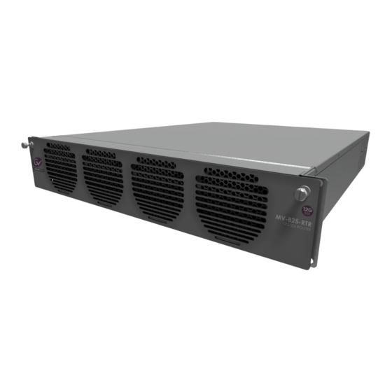
Page 38: Chassis Overview
Hardware Description Chassis Overview Chassis Overview The MV-825-RTR is a 2RU 19” rack-mount chassis with connectors at the rear (see Figure 2- Front view Rear view Fig. 2-1: MV-825-RTR Unit Views The chassis is air-cooled and the airflow is front-to-back. The unit has a door at the front with a grille and integral cooling fans. -
Page 39: Chassis Front
MV-825-RTR Multiviewer with Integrated Router User Manual Chassis Front The front door has two knurled fastening screws and a grille, behind which are fitted four fans which draw air in at the front, see Figure 2-2. Knurled door fasteners Fig. 2-2: MV-825-RTR Front View, Door Closed With the front door open, some inner card status LEDs are visible: However, there is normally no reason to open the front door. -
Page 40: To Close The Front Door
Hardware Description To Close the Front Door To Close the Front Door Before closing the door: 1 Check that the fan supply wires are all connected to the front edge of the MV-825-RTR main card. See Figure 2-4 Fig. 2-4: Fan Supply Wires Connected to front of the Main Card To close the door: 2 Pull the door upwards into a vertical position (the door hinges along its bottom edge) and then push it fully into the front of the chassis. -
Page 41: Front Indicators
MV-825-RTR Multiviewer with Integrated Router User Manual Front Indicators There are no external front indicators. Internally, with the front door open and dropped down, the front edge of the front main module can be seen in the top half of the chassis frame. This is the MV-825-RTR main card, see Figure 2-5. - Page 42 Hardware Description Front Indicators Sub-module LEDs on main card, under sub-module DIP switches (Engineering Use Only) Connectors for (Engineering Use Only) Front edge of card “A” = Fan Supply header connectors Fig. 2-6: Front Main Card - Status Indicating LEDs and Fan Supply Headers...
- Page 43 Green Flashing (2Hz): Hardware communications fault detected. Status Contact Grass Valley Customer Support, see Note 1. Note 1: For Grass Valley Customer Support contact details, Grass Valley Technical Support, on page 239. CAUTION: Electrostatic Damage: Static precautions must be observed when touching or handling cards...
-
Page 44: Rear Panel
Note: The ‘Main PCB serial number’ is found: • in the multiviewer block’s ‘System-Setup’ control screen; or • on the unit’s start-up splash screen at boot up. (See the MV-8 Series Core Multiviewer User Manual for details, see Related Documents, on page iii.) -
Page 45: Rear Panel Connectors
MV-825-RTR Multiviewer with Integrated Router User Manual Rear Panel Connectors Rear panel (no annotation) Router Video Outputs 1 to 48 Router Video Inputs 1 to 48 (48x 12G HD-BNC connectors) (48x 12G HD-BNC connectors) HD BNC Video Outputs, on page 24. HD BNC Video Inputs, on page 23. - Page 46 Hardware Description Rear Panel Connectors Table 2-2: MV-825-RTR Rear Connectors Rear Connection Description Inputs 1 to 48 48x HD-BNC 12G router video inputs. (See HD BNC Video Inputs, on page 23.) 48x HD-BNC 12G router video outputs. Outputs 1 to 48 (See HD BNC Video Outputs, on page 24.)
-
Page 47: Rear Connectors
MV-825-RTR Multiviewer with Integrated Router User Manual Rear Connectors HD BNC Video Inputs The video inputs form sources for the router. HD-BNC connector (12G) Corresponding Catsii LED indicator, Catsii LEDs, on page 24. Input 1 Input 48 Fig. 2-9: MV-825-RTR Router Video Input Connectors (Rear Left-hand Side) 1 to 48 Connector Label and LED The positioning of the rear video BNC connector’s label and its corresponding Catsii LED is shown in Figure 2-10. -
Page 48: Hd Bnc Video Outputs
Hardware Description HD BNC Video Outputs HD BNC Video Outputs The video outputs are destinations for the router. HD-BNC connector (12G) Corresponding Catsii LED indicator, Catsii LEDs, on page 24. Output 1 Output 48 Fig. 2-11: MV-825-RTR Router Video Output Connectors (Rear Right-hand Side) 1 to 48 Catsii LEDs The Catsii LEDs are on the rear panel at each router video input or output HD-BNC connector. -
Page 49: Bnc Reference Connectors
MV-825-RTR Multiviewer with Integrated Router User Manual BNC Reference Connectors The reference input is used for SDI video input timing and display output timing. There are two analog reference inputs and two “loop-through” outputs on MV-825-RTR. The reference inputs are unterminated. Termination should be done at the reference output connector with a 75 ohm termination, or the reference signal may be “looped through”, via the Reference Out connector, and taken to another piece of equipment (where the signal must be terminated, at the end of the loop). - Page 50 Hardware Description AC Mains Inlets Table 2-4: PSU Status LED PSU Module Outputs Status LED Color Comment Main Output Standby Output Normal Operation Green Stand by Flashing AC Mains Present .Green. Warning Flashing Over-current, Under-voltage, or .Yellow Over-voltage warning Fault Over-current, Under-voltage, or Fan Fault or...
-
Page 51: Multiviewer Head Display Outputs
• internal FPGA upgrading was unsuccessful; or • internal FPGAs fail to load during unit boot. Note: A unit upgrade to the same version may be carried out to recover a unit if FPGA upgrading was unsuccessful. Otherwise, contact Grass Valley support. -
Page 52: Rear Connectors - Aux Inputs/Outputs
Hardware Description Rear Connectors - Aux Inputs/Outputs Rear Connectors - Aux Inputs/Outputs The ‘Aux‘ connections are reserved for future use. Aux Inputs SFP cage for 2x SDI inputs, reserved for future use. 2x Aux In 2x Aux Out Fig. 2-15: MV-825-RTR Aux Inputs and Outputs Aux Outputs SFP cage for 2x SDI outputs, reserved for future use. -
Page 53: Rear Connectors - Network Interface Ports
MV-825-RTR Multiviewer with Integrated Router User Manual Rear Connectors - Network Interface Ports Router and Multiviewer Control Ethernet ports: • ROUTER 1 and ROUTER 2 are for router control. • MV1 and MV2 are for multiviewer control. Link Status LED’s 1G Ethernet RJ45s 1G Ethernet RJ45s ‘ROUTER 1’... -
Page 54: Ltc And Gpi Connector
Hardware Description LTC and GPI Connector LTC and GPI Connector LTC and GPIO Connector Pin-outs Female high density 26 way 'D' type connector assignments Fig. 2-17: Female High Density 26 Way 'D' Type LTC and GPIO Connector The following table gives the pin assignments for the LTC and GPIO connector: Table 2-7: Female High Density 26 Way 'D' Type LTC and GPIO Connector Pin Number Signal... - Page 55 MV-825-RTR Multiviewer with Integrated Router User Manual Note: MV-825-RTR GPI outputs: Open collector outputs. Require external pull-up resistors of value between 10 kΩ and 100 kΩ. Each output can sink up to 100 mA. • “+5 V DC Out” pins are provided on the connector for this purpose. •...
- Page 56 Hardware Description LTC and GPI Connector...
-
Page 57: Unit Installation
3 Unit Installation Summary of chapter contents: This section describes the unpacking and installation of the MV-825-RTR unit. Unit Installation Unpacking ..............page 34 Environmental Considerations . -
Page 58: Unpacking
1 Carefully unpack the system components and check them against the packing list. If there is anything incorrect, then notify your Grass Valley Partner, or Grass Valley, at once.... - Page 59 MV-825-RTR Multiviewer with Integrated Router User Manual Figure 3-1 shows the external chassis air flow and air intake and exhaust holes. Figure 3-2 shows the internal chassis air flow. Air Flow Out Side Air Exhaust holes Air Flow In Front Air Intake holes Fig.
-
Page 60: Cooling Fan Failure
Depending on the length of time the MV-825-RTR has been run with no fan the unit may need to be returned for checking and repair. Contact Grass Valley or your Grass Valley dealer to discuss the situation. -
Page 61: Rack Mounting
MV-825-RTR Multiviewer with Integrated Router User Manual Rack Mounting Location in Rack The MV-825-RTR is designed to be installed in a standard 483mm (19 inch) equipment rack for use. The unit requires a 2RU high space within a rack. The following precautions should be observed: 1 Do not obstruct the front air intake holes. - Page 62 Unit Installation Mounting the MV-825-RTR into a Rack Fitting the Unit 1 Position the MV-825-RTR in the rack on the shelf. Use the correct lifting procedures. 2 Open the MV-825-RTR front door (see Chapter 2 To Open the Front Door, on page 15)....
- Page 63 MV-825-RTR Multiviewer with Integrated Router User Manual 3 Secure the MV-825-RTR chassis in the rack at each mounting hole using 4x M6 (1/4 inch) screws. See Figure 3-4. (Screws are available from rack suppliers.) Chassis Rack Mounting Holes MV-825-RTR Chassis Rack ...
-
Page 64: Cabling Up In A Rack
Unit Installation Cabling Up in a Rack Cabling Up in a Rack When connecting cables to the MV-825-RTR, it is recommended that cable supports are used (clamps and bars) to relieve the strain on rear connectors. See Chapter 2 Rear Connectors, on page 23. -
Page 65: Powering
MV-825-RTR Multiviewer with Integrated Router User Manual Powering WARNING: To reduce the risk of electric shock, plug each power supply cord into separate branch circuits employing separate service grounds. Power consumption is listed in Appendix A Power, on page 189. Note: Output disruption and MV-825-RTR starting up: While the MV-825-RTR unit starts up or restarts, there may be disruption to... -
Page 66: Booting Up
Up to 3 minutes Note: If the MV-825-RTR front main card does not have a Flashing “CPU Heartbeat” LED when it has finished booting, contact Grass Valley Support. When the MV-825-RTR has finished starting up, the start-up splash screen goes away and is replaced by the video wall content of the multiviewer project running on the MV-825-RTR. -
Page 67: The Start-Up Splash Screen
Maintenance of the Core Multiviewer , on page 184 Note: Use the ‘1G1’ network interface when performing the initial unit configuration with Grass Valley RollCall control panel. The ‘Eng’ interface is a reserved internal IP network interface. Do not use this IP address. -
Page 68: Initial Connection And Configuration
Unit Installation Initial Connection and Configuration Initial Connection and Configuration The multiviewer and the router parts of the MV-825-RTR require separate initial connection and configuration: • Core Multiviewer Initial Connection and Configuration • Router Initial Connection and Configuration Core Multiviewer Initial Connection and Configuration Items required: •... - Page 69 MV-825-RTR Multiviewer with Integrated Router User Manual Initial Connection to the Core Multiviewer To make the initial connection to the MV-825-RTR unit’s core multiviewer: 1 Run GV Orbit Client. Fig. 3-8: GV Orbit Client Initial Screen 2 Click on the RollCall Control Screen icon. (Or, if a GV Orbit project is already open in GV Orbit Client, ...
- Page 70 Unit Installation Core Multiviewer Initial Connection and Configuration Banner information, see Banner Information in a Control Screen. Click on x on tab to close the control screen Fig. 3-9: Example Multiviewer Control Screen To perform initial configuration, proceed to Initial Configuration for Core Multiviewer, on page 47.
- Page 71 MV-825-RTR Multiviewer with Integrated Router User Manual The Selection box allows the user to access the various control screens for the unit. The System box displays the core multiviewer system status at the top of each menu page: • OK - the multiviewer is working correctly. •...
- Page 72 Unit Installation Core Multiviewer Initial Connection and Configuration Note: When driving a 4K monitor, each multiviewer head display output drives one quadrant of the 4K monitor. Some 4K monitors have four 1080p inputs, so they can be fed from four multiviewer 1080p outputs. If this is not the case, a separate adapter must be used to convert four multiviewer head display outputs to a single 4K signal suitable for the monitor.
-
Page 73: Router Initial Connection And Configuration
MV-825-RTR Multiviewer with Integrated Router User Manual Router Initial Connection and Configuration Some basic settings will need to be set up for the router functional block within the MV- 825-RTR. Default Routing for New MV-825-RTR Initially, in a new MV-825-RTR unit, the router part is configured with a default routing which has crosspoints set to have straight-through, one-to-one routing. - Page 74 Unit Installation Router Initial Connection and Configuration Router Initial Connection and Configuration (Control Screen) Items required: • See Core Multiviewer Initial Connection and Configuration, on page 44. Note: Router control Ethernet port: Typically, a new MV-825-RTR will be using a default IP address (see Default IP Addresses, on page 195) on rear Ethernet port “Router 1”...
- Page 75 MV-825-RTR Multiviewer with Integrated Router User Manual Fig. 3-13: Router Configuration - Comms Setup Note: The Router configuration control screen is fully described in Chapter 5, Router Configuration Control Screens, on page 57...
- Page 76 Unit Installation Router Initial Connection and Configuration Initial Configuration for Router The initial configuration of the router includes setting up: • MV-825-RTR router IP addresses, and • communication settings. After initial configuration, the MV-825-RTR unit may be connected to the house IT network and all remaining MV-825-RTR router configuration settings can be set up.
- Page 77 MV-825-RTR Multiviewer with Integrated Router User Manual Initial MV-825-RTR router connection and configuration should be carried out on a separate IT network, separate from any house IT network. The initial configuration sets up the MV- 825-RTR’s router block - IP addresses, communication settings etc. Note: Router Control Ethernet port:...
-
Page 78: Getting Started
Unit Installation Getting Started Getting Started When the MV-825-RTR unit has re-started, the new settings for the multiviewer and for the router will be adopted by the MV-825-RTR. The MV-825-RTR unit can then be connected to your house IT network. Please refer to Chapter 10, Getting Started, on page 159, to get started:... -
Page 79: Core Mv-8 Control Screens
Control screens for the core multiviewer are independent of the MV-825-RTR’s video router. For information about the control screens of the core multiviewer, please refer to the ‘Core MV Control Screens’ chapter of the MV-8 Series Core Multiviewer user manual. - Page 80 Core MV-8 Control Screens...
-
Page 81: Router Configuration Control Screens
5 Router Configuration Control Screens Summary of chapter contents: Router Configuration Control Screens Introduction ..............page 58 Configuration of Router. -
Page 82: Introduction
Router Configuration Control Screens Introduction Introduction An MV-825-RTR broadly comprises a router function and a multiviewer function. Router Fig. 5-1: MV-825-RTR Functions Configuration of Router This section describes the control screens (RollCall templates) for configuration of the router, which comprises: a router controller, main video router, an internal multiviewer input crosspoint, and an internal multiviewer head crosspoint. -
Page 83: Configure Mv-825-Rtr Router Block
MV-825-RTR Multiviewer with Integrated Router User Manual Configure MV-825-RTR Router Block The control screens are accessible via Grass Valley’s RollCall Control Panel tool, or via Grass Valley’s GV Orbit Client tool. Note: RollCall Control Panel When installing the RollCall Control Panel software on your computer, use version 4.17.1 or later. -
Page 84: Accessing Configuration Control Screen In Gv Orbit Client
Router Configuration Control Screens Accessing Configuration Control Screen in GV Orbit Client To access the router configuration control screens: 3 Double-click on the first item. See Figure 5-3. Control screens are downloaded from the device and shown. See Figure 5-3 Accessing Configuration Control Screen in GV Orbit Client 1 Run GV Orbit Client. - Page 85 MV-825-RTR Multiviewer with Integrated Router User Manual Fig. 5-5: MV-825-RTR Router Configuration Control Screen...
-
Page 86: Router - Configuration Screens
Router Configuration Control Screens Router - Configuration Screens Router - Configuration Screens Note: “S” and “P” buttons on Control Screens: After entering information in each text box, always click on the adjacent “S” button or press Return/Enter to locally save the new setting. -
Page 87: Router - Unit Information Screen
MV-825-RTR Multiviewer with Integrated Router User Manual Router - Unit Information Screen The (MV-825-RTR router) Unit Information control screen shows unit information. The screen contains some read-only information as well as read-write settings that can be set up in the screen. Note: The information may also be shown/modified on the unit’s web page. - Page 88 Router Configuration Control Screens Router - Unit Information Screen Table 5-1: MV-825-RTR Unit Information Screen Item Description Software Version Version of software running on the MV-825-RTR router. Software Build Date Date when the software was built. Controller FPGA Number Identifier for the firmware running on the MV-825-RTR router controller circuitry.
- Page 89 MV-825-RTR Multiviewer with Integrated Router User Manual Table 5-2: MV-825-RTR Unit Information Screen - Further Settings Item Description Use Long Names (32 Check box. chars) Select to use long Source and Destination names on the RollCall routing control screens: Time Auto Set: Time selection radio buttons: NTP Server Radio button....
- Page 90 Router Configuration Control Screens Router - Unit Information Screen Table 5-2: MV-825-RTR Unit Information Screen - Further Settings (continued) Item Description TimeZone Text box. Enter a Posix-style string to define the timezone to be used by the unit’s time for the router of the MV-825-RTR unit. Example: •...
-
Page 91: Router - System Information Screen
MV-825-RTR Multiviewer with Integrated Router User Manual Router - System Information Screen The (MV-825-RTR router) System Information control screen shows system information. The screen contains some read-only information as well as some controls. Note: The information/controls may also be shown/modified on the unit’s web page. Reference controls Fig. - Page 92 Router Configuration Control Screens Router - System Information Screen Table 5-4: MV-825-RTR System Information Screen - Reference Controls Item Description Reference Standard: Radio buttons. Select the reference signal to be used as the reference standard for the router and for the core multiviewer. The crosspoints switch routes timed with the selected reference.
-
Page 93: Router - Router Port Configuration Screen
MV-825-RTR Multiviewer with Integrated Router User Manual Router - Router Port Configuration Screen Router crosspoint (60x48) The (MV-825-RTR router) Router Port Configuration control screen enables the user to configure input and output router ports of the Router crosspoint within the MV-825-RTR unit. - Page 94 Router Configuration Control Screens Router - Router Port Configuration Screen Router crosspoint: • Sources (source, input ports); • Destinations (destination, output ports) Router Outputs (1 to 48) Router Inputs (1 to 48) Internal Multiviewer Head signals (1 to 12) Fig. 5-9: Router Crosspoint Port Configuration Screen Note: The Router crosspoint has: •...
-
Page 95: Input Ports
MV-825-RTR Multiviewer with Integrated Router User Manual Input Ports Input ports: • Router Input (1 to 48). • Internal Multiviewer Head signals 1 to 12. For Router crosspoint Sources (input ports of the cross point), the screen shows the: • port name, •... -
Page 96: Router - Multiviewer Input Port Configuration Screen
Router Configuration Control Screens Router - Multiviewer Input Port Configuration Screen Router - Multiviewer Input Port Configuration Screen MV Input crosspoint (48x48) The (MV-825-RTR router) Multiviewer Input Port Configuration control screen enables the user to configure input and output router ports of the MV Input crosspoint within the MV-825-RTR unit. - Page 97 MV-825-RTR Multiviewer with Integrated Router User Manual MV Input crosspoint: • Sources (source, input ports); • Destinations (destination, output ports) Fig. 5-10: MV Input Crosspoint Port Configuration Screen Note: MV Input crosspoint has: • 48 Sources = Router Inputs (1 to 48) •...
-
Page 98: Router - Multiviewer Head Port Configuration Screen
Router Configuration Control Screens Router - Multiviewer Head Port Configuration Screen Router - Multiviewer Head Port Configuration Screen MV Head crosspoint (60x12) The (MV-825-RTR router) Multiviewer Head Port Configuration control screen enables the user to configure input and output router ports of the MV Head crosspoint within the MV-825-RTR unit. - Page 99 MV-825-RTR Multiviewer with Integrated Router User Manual MV Head crosspoint: • Sources (source, input ports); • Destinations (destination, output ports) Fig. 5-11: MV Head Crosspoint Port Configuration Screen Note: The MV Head crosspoint has: • 60 Sources = Router Inputs (1 to 48) + internal Multiviewer Head signals (1 to 12) •...
-
Page 100: Router - Comms Setup Screen
Router Configuration Control Screens Router - Comms Setup Screen Router - Comms Setup Screen The (MV-825-RTR router) Comms Setup control screen enables the user to access communication port settings for the router within an MV-825-RTR unit. A unit restart is required for changes on this screen to take effect. -
Page 101: Comms Setup - Ip Settings
MV-825-RTR Multiviewer with Integrated Router User Manual Comms Setup - IP Settings Network interface settings are shown and may be configured here for both rear router network interface ports. Fig. 5-13: Comms Setup Screen - IP Address Section CAUTION When two router network ports are used (router IP Ports 1 and 2, i.e. -
Page 102: Comms Setup - Rollcall Items
Router Configuration Control Screens Comms Setup - RollCall Items Table 5-5: Comms Setup - IP Port 1 and 2 Settings (continued) Item Description MAC Address Displays the MAC address of the MV-825-RTR router block. Note 1: “S” and “P” buttons - After entering information in each text box, always click on the adjacent “S”... -
Page 103: Comms Setup - General
MV-825-RTR Multiviewer with Integrated Router User Manual Table 5-7: Comms Setup - RollCall Items Item Description IP Share Port Text Box. Enter network port for use by RollCall. Default is 2050. See Note 1. Any Log Server Check box. •... -
Page 104: Comms Setup - Rollcall
Router Configuration Control Screens Comms Setup - RollCall+ Table 5-8: Comms Setup - General Items Item Description General Switcher (SW-P-02): Check box. Enable Select to enable the unit’s general switcher protocol interface. Text box. Enter IP port number for general switcher protocol. IP Port Default = 2002.... - Page 105 MV-825-RTR Multiviewer with Integrated Router User Manual Table 5-9: Comms Setup - RollCall+ Items Item Description Enable Check box. Select to enable RollCall+ on the MV-825-RTR’s router block. Domain Text box. Enter a RollCall+ domain number for the MV-825-RTR’s router block.
-
Page 106: Comms Setup - Snmp
Router Configuration Control Screens Comms Setup - SNMP Comms Setup - SNMP Fig. 5-17: Comms Setup - SNMP Items Table 5-10: Comms Setup - SNMP Items Item Description Enable Check box. Select to enable the SNMP protocol interface. Communities: (SNMP name fields for Get, Set and Trap commands/messages.) Text box.... -
Page 107: Comms Setup - Syslog (Logging)
MV-825-RTR Multiviewer with Integrated Router User Manual Comms Setup - Syslog (Logging) Fig. 5-18: Comms Setup - Syslog Items Table 6 Comms Setup - Syslog Items Item Description Enable Check box. Select to enable the unit’s logging interface. (Logging Format:) Radio buttons:... -
Page 108: Comms Setup - Restart Unit
Router Configuration Control Screens Comms Setup - Restart Unit Comms Setup - Restart Unit Fig. 5-19: Comms Setup - Restart Unit Click Restart Unit after local changes have been made and saved on the Comms Setup screen. Unit restart begins immediately. Table 5-11: Comms Setup - Restart Unit Item Description... -
Page 109: Router - Log Fields Screen
MV-825-RTR Multiviewer with Integrated Router User Manual Router - Log Fields Screen The (MV-825-RTR router) Log Fields control screen displays the state of RollCall log fields generated by the MV-825-RTR’s router block. Fig. 5-20: Log Fields Screen Table 5-12: MV-825-RTR Multiviewer with Integrated Router Logging Fields (Read-only information) Item Description... - Page 110 Router Configuration Control Screens Router - Log Fields Screen...
-
Page 111: Router Crosspoint Control Screens
6 Router Crosspoint Control Screens Summary of chapter contents: Router Crosspoint Control Screens Introduction ..............page 88 Monolithic Overall Router Crosspoint . -
Page 112: Introduction
Router Crosspoint Control Screens Introduction Introduction An MV-825-RTR broadly combines a router function and a multiviewer function. Router Fig. 6-1: MV-825-RTR The router function presents three router crosspoints (see Figure 6-2) to the user: 1 Main Video Router crosspoint (size = (48+12) in x 48 out); 2 MV Head crosspoint (size = (48+12) in x 12 out);... -
Page 113: Monolithic Overall Router Crosspoint
MV-825-RTR Multiviewer with Integrated Router User Manual Monolithic Overall Router Crosspoint The three router crosspoints of the MV-825-RTR are in reality implemented as one, monolithic crosspoint of overall size 62x110. See Figure 6-3a and Figure 6-3b. a) Normally presented to user - b) Presented on MV-825-RTR RollCall router crosspoint control screen - ... -
Page 114: This Chapter
Router Crosspoint Control Screens This Chapter This Chapter This chapter describes the control screens (RollCall templates) for control of the monolithic router crosspoint within the MV-825-RTR. Monolithic Crosspoint Sources and Destinations Table 6-1 Monolithic Crosspoint Sources Monolithic Default Source Crosspoint Signal Description Name Source Number... - Page 115 MV-825-RTR Multiviewer with Integrated Router User Manual Table 6-2 Monolithic Crosspoint Destinations Monolithic Crosspoint Default Name Signal Description Source Number VOut1 VOut2 VOut3 VOut4 MV-825-RTR Router Video Outputs (48) VOut45 VOut46 VOut47 VOut48 AuxOut1 Aux outputs, reserved for future use (2) AuxOut2 MVHead1 MVHead2...
-
Page 116: Accessing Mv-825-Rtr Router Crosspoint Control Screen
Router Crosspoint Control Screens Accessing MV-825-RTR Router Crosspoint Control Screen Accessing MV-825-RTR Router Crosspoint Control Screen The crosspoint control screens are accessible via Grass Valley’s RollCall Control Panel tool. Note: RollCall Control Panel When installing the RollCall Control Panel software on your computer, use version 4.17.1 or later. -
Page 117: Monolithic Crosspoint Control Screen
MV-825-RTR Multiviewer with Integrated Router User Manual Monolithic Crosspoint Control Screen The control screen enables the user to make routes in the monolithic crosspoint and to edit Source and Destination names and set protected Destinations. Routing is initially set to be 1-to-1. Selection: XY Panel Control, and Routing screens XYPanel Control Screen - Routing Tab, on page 94... -
Page 118: Xypanel Control Screen - Routing Tab
Router Crosspoint Control Screens XYPanel Control Screen - Routing Tab XYPanel Control Screen - Routing Tab A crosspoint control screen is shown in Figure 6-6. The crosspoint’s routing is initially set to be 1-to-1. Tabs: XYPanel Control Screen - Edit Names Tab, on page 98 XYPanel Control Screen - Edit Names Tab, on page 98... - Page 119 MV-825-RTR Multiviewer with Integrated Router User Manual Destination Protect A protected Destination (called Lock Route on the web page) cannot be routed to. The protected/locked status of each Destination is shown on the Destination buttons, with a padlock symbol to denote “locked” (i.e. protected). See Figure 6-7a. To protect a destination from the XY Panel Routing screen: 1 Select a Destination.
- Page 120 Router Crosspoint Control Screens XYPanel Control Screen - Routing Tab Filter Names The displayed Source and/or Destination names can be filtered. To filter the displayed names: 1 Click in the Filter text box of either the Source or Destination grid. Some Filter controls are shown.
- Page 121 MV-825-RTR Multiviewer with Integrated Router User Manual A RegEx example is shown in Figure 6-10. Regular expression entered = ‘ . *2$’ Filter displays names which end with ‘2’ Fig. 6-10: Regular Expression Filter Example Note: Regular expressions can define a search pattern in a text string or name.
-
Page 122: Xypanel Control Screen - Edit Names Tab
Router Crosspoint Control Screens XYPanel Control Screen - Edit Names Tab XYPanel Control Screen - Edit Names Tab The Edit Names tab enables a user to edit the crosspoint Source button names and Destination button names. Source button names edited Enter a new button name Fig. -
Page 123: Xypanel Control Screen - Edit Protect Tab
MV-825-RTR Multiviewer with Integrated Router User Manual XYPanel Control Screen - Edit Protect Tab The Edit Protect tab enables a user to edit all the crosspoint Destination Protects easily from one screen. All locked, or protected, Destinations are shown with a padlock symbol on their buttons. -
Page 124: Xypanel Control Screen - Options Tab
Appendix 1, ‘XY Panel’ , in that user manual, contains information about the Options. (User manual available from the Grass Valley web site by searching for ‘rollcall’ on the website and selecting ‘RollCall Control Panel.book’ in the search results. You may need to register with Grass Valley first, which is free.) - Page 125 MV-825-RTR Multiviewer with Integrated Router User Manual The XY Panel always starts in User Mode. The option controls are only available when in Admin Mode. (If required, a password can be set up to secure this mode, see the ex-SAM ‘RollCall Control Panel User Manual’...
- Page 126 Router Crosspoint Control Screens XYPanel Control Screen - Options Tab Table 6-3: XY Panel Control Screen - Option Controls (continued) Option Description Router Display Define additional information to be displayed on the source and destination buttons. Popout Display Customize the display of the XY panel when it is used as a pop-out screen.
- Page 127 MV-825-RTR Multiviewer with Integrated Router User Manual Table 6-3: XY Panel Control Screen - Option Controls (continued) Option Description Button Sizes The source and destination buttons can be resized and button text formatted.
- Page 128 Router Crosspoint Control Screens XYPanel Control Screen - Options Tab Table 6-3: XY Panel Control Screen - Option Controls (continued) Option Description Panel Sizes Adjust the number of rows and columns of source and destination buttons of the XY panel, and the spacing between rows/columns. Button Maps Use button maps to define alternative mappings of the source and destination buttons.
- Page 129 MV-825-RTR Multiviewer with Integrated Router User Manual Table 6-3: XY Panel Control Screen - Option Controls (continued) Option Description Manage Options Save and load settings, restore defaults and set an admin password.
-
Page 130: Routing Screen
Router Crosspoint Control Screens Routing Screen Routing Screen The Routing screen can be used to make routes. It is an alternative screen to the XY Panel screen (XYPanel Control Screen - Routing Tab, on page 94). Take button Protected check box Destination selection list, scrollable Source selection list, scrollable Fig. - Page 131 MV-825-RTR Multiviewer with Integrated Router User Manual When a Destination is protected (or when its ‘route is locked’) then no route can be made to that Destination. To protect a Destination (or ‘lock its route’) from the Routing screen: 1 Select a Destination. 2 Select the Protected check box.
- Page 132 Router Crosspoint Control Screens Routing Screen a) Protect Destination in Routing Screen b) Destination Protected Shown in XY Panel Control Screen Fig. 6-17: Destination Protect: a) From Routing Screen; b) Shown in XY Panel Control Screen.
-
Page 133: Routing Examples
MV-825-RTR Multiviewer with Integrated Router User Manual Routing Examples Simple Route with XY Panel Control Screen In the XY Panel Control screen’s Routing Tab, to make a simple route for a crosspoint: 1 Select a Destination. The currently-routed Source is highlighted. 2 Select a new Source. - Page 134 Router Crosspoint Control Screens Simple Route with XY Panel Control Screen 4) Click Undo The new route is made. Fig. 6-19: Route Made, Undo If Required To undo this (if required): 4 Click Undo. The routing is undone an reverts to how it was before. Note: After a timeout period, the Undo button becomes inactive.
-
Page 135: Take Information While Routing
MV-825-RTR Multiviewer with Integrated Router User Manual Take Information while Routing Selected Destination Take button Currently-routed Source Pre-Selected Source Fig. 6-21: Take Information Simple Route with Routing Screen In the Routing screen, to make a simple route for a crosspoint: 1 Select a Destination. - Page 136 Router Crosspoint Control Screens Simple Route with Routing Screen (The routed source is shown in the ‘Sources’ column. Alternatively, change to the XY Panel Control screen to see the source routing, see Figure 6-23.) The new route is made. Fig. 6-23: Route Made...
-
Page 137: Router Config And Control Web
7 Router Config and Control Web Pages Summary of chapter contents: Router Config and Control Web Pages Open Home Web Page ............page 114 Navigation Side Bar. -
Page 138: Open Home Web Page
Router Config and Control Web Pages Open Home Web Page Open Home Web Page Note: An MV-825-RTR unit comprises an integral router and integral core multiviewer. To access the router’s web page, use: • the router’s IP address; and • rear Ethernet control port ‘Router 1’ or ‘Router 2’ . (Default IP addresses are listed in Ethernet Rear Panel Connectors, on... -
Page 139: Navigation Side Bar
MV-825-RTR Multiviewer with Integrated Router User Manual The Home web page shows: • navigation controls in a side-bar; • a functional block diagram of the MV-825-RTR (see Functional Block Diagram, Figure 1-3 on page 6); and • some (router) system information. The Home web page is described in Home Page, on page 116. -
Page 140: Home Page
Router Config and Control Web Pages Home Page Home Page An image of the Home page is shown in Figure 7-2 on page 116. Functional Block Diagram The block diagram shown on the Home web page is described in Functional Block Diagram, on page 6. -
Page 141: Router Information
MV-825-RTR Multiviewer with Integrated Router User Manual Router Information The information shown on the Home page is described in Table 7-2. Table 7-2: Home Page Router Information Item Description System Information: (Read-only items.) Serial number of the router hardware block within the MV-825-RTR unit. Serial Number Note: This is not the same as the Unit Serial Number. - Page 142 Router Config and Control Web Pages Router Information Table 7-2: Home Page Router Information (continued) Item Description Apply Click to apply the selected reference signal standard type. The selected router system reference standard is shown in the System Status information, ‘Reference Standard Selected’ . System Status: (Read-only items.)...
-
Page 143: Catsii Colors Page
MV-825-RTR Multiviewer with Integrated Router User Manual Catsii Colors Page The colors associated with the Catsii LED indicators at each rear video input can be selected. The LEDs report the video standard detected at each input. 1 Select a color. 2 Click Apply to apply the change to the unit. -
Page 144: Router Crosspoint
Router Config and Control Web Pages Router Crosspoint Router Crosspoint The Router crosspoint controls the MV-825-RTR router. I.e. the routing of any MV-825-RTR router video input to any MV-825-RTR router video output. The Router crosspoint pages enable a user to configure crosspoint inputs and outputs (router sources and destinations) and control the crosspoint routing. -
Page 145: Make A Route In A Crosspoint
MV-825-RTR Multiviewer with Integrated Router User Manual Make a Route in a Crosspoint A route can be made from the Router Crosspoint Page web page. Note: Routing is a common operation for the other crosspoints. See: • Router Crosspoint Page, on page 123, •... - Page 146 Router Config and Control Web Pages To Lock a Destination/Route in a Crosspoint 3 Click OK. The Destination is locked (protected) and the route to it locked. Select Destination. Click Lock Route. Locked Destination and route. Fig. 7-6: Lock Destination Routing to a Locked Destination/Route If a route is attempted to a locked Destination, ...
-
Page 147: Router Crosspoint Page
MV-825-RTR Multiviewer with Integrated Router User Manual Router Crosspoint Page This crosspoint page is similar to the MV Input Crosspoint Page Note: MV Head Crosspoint Page. This page enables a user to make routes with the Router crosspoint in the MV-825-RTR. (The router/crosspoint architecture of the MV-825-RTR is described in Functional Block Diagram, on page 6.) -
Page 148: Source Buttons
Router Config and Control Web Pages Source Buttons Source Buttons Source Button, shows: Source Name. Currently-routed Source (to a selected Destination) Pre-selected Source Fig. 7-8: Crosspoint Source Buttons Primary quad-link Source Button Other members of quad-link group. Fig. 7-9: Quad-Link Source Buttons... -
Page 149: Destination Buttons
MV-825-RTR Multiviewer with Integrated Router User Manual Destination Buttons Destination Button, shows: Destination Name and (currently-routed Source). Selected Destination Fig. 7-10: Crosspoint Destination Buttons Primary quad-link Destination Button Other members of quad-link group. Fig. 7-11: Quad-link Destination Buttons... -
Page 150: Router Crosspoint Inputs Page
Router Config and Control Web Pages Router Crosspoint Inputs Page Router Crosspoint Inputs Page This page enables a user to configure inputs to the Router crosspoint. Note: The Router crosspoint shares some inputs with other crosspoints and common input settings are reflected in other web pages. ... - Page 151 MV-825-RTR Multiviewer with Integrated Router User Manual Apply button Note: The Apply button is grayed out until a change has been made on the page. All Router Inputs list item Router Inputs 1 to 48 All Internal Multiviewer Head signals (12) list item Internal Multiviewer Head signals 1 to12 Fig.
- Page 152 Router Config and Control Web Pages Router Crosspoint Inputs Page 1 Click Apply to apply the changes. A confirming pop-up dialog informs the user that changes have been applied. 2 Click OK in the pop-up dialog to continue. Table 7-3 describes the list columns on the page. Table 7-3: Router Crosspoint Inputs Information Column Item Description...
-
Page 153: Router Crosspoint Outputs Page
MV-825-RTR Multiviewer with Integrated Router User Manual Router Crosspoint Outputs Page This page enables a user to configure outputs from the Router crosspoint. The page is shown in Figure 7-13 and displays a list of crosspoint outputs (destinations of the crosspoint). For the Router crosspoint, these are: •... - Page 154 Router Config and Control Web Pages Router Crosspoint Outputs Page Table 7-4: Router Crosspoint Outputs Information Column Item Description Physical (Read-only) The name of each output in the physical unit. Check box. To designate four outputs as a 4K quad-link: •...
-
Page 155: Mv Input Crosspoint
MV-825-RTR Multiviewer with Integrated Router User Manual MV Input Crosspoint Note: The MV Input crosspoint has similar web pages to the Router crosspoint and the information shown and the controls available are similar to the Router crosspoint pages. The MV Input crosspoint can route any of the 48 MV-825-RTR router video inputs to any of the 48 internal core multiviewer inputs (and hence to video wall tiles). -
Page 156: Routing And Locking
Router Config and Control Web Pages Routing and Locking Initially, the routes set up are ‘1:1’ . Note: I.e. Crosspoint input 1 routed to crosspoint output 1, input 2 to output 2, 3 to 3, etc. See: • MV Input Crosspoint Page, on page 133. -
Page 157: Mv Input Crosspoint Page
MV-825-RTR Multiviewer with Integrated Router User Manual MV Input Crosspoint Page Note: This crosspoint page is similar to the Router Crosspoint Page. See Router Crosspoint Page for more information. This page enables a user to make routes with the MV Input crosspoint in the MV-825-RTR. (The router/crosspoint architecture of the MV-825-RTR is described in Functional Block Diagram, on page 6.) -
Page 158: Mv Input Crosspoint Inputs Page
Router Config and Control Web Pages MV Input Crosspoint Inputs Page MV Input Crosspoint Inputs Page This page enables a user to configure inputs to the MV Input crosspoint. Note: The MV Input crosspoint shares some inputs with other crosspoints and common input settings are reflected in other web pages. - Page 159 MV-825-RTR Multiviewer with Integrated Router User Manual Apply button All Router Inputs (48) list item Router Inputs 1 to 48 Fig. 7-16: MV Input Crosspoint Inputs Page The page lists information about each crosspoint input and enables some input settings to be configured.
-
Page 160: Mv Input Crosspoint Outputs Page
Router Config and Control Web Pages MV Input Crosspoint Outputs Page MV Input Crosspoint Outputs Page This page enables a user to configure outputs from the MV Input crosspoint. The page is shown in Figure 7-13 and displays a list of crosspoint outputs (destinations of the crosspoint). - Page 161 MV-825-RTR Multiviewer with Integrated Router User Manual A confirming pop-up dialog informs the user that changes have been applied. 2 Click OK in the pop-up dialog to continue. Table 7-4 on page 130 describes the list columns on the page.
-
Page 162: Mv Head Crosspoint
Router Config and Control Web Pages MV Head Crosspoint MV Head Crosspoint Note: The MV Head crosspoint has similar web pages to the Router crosspoint and the information shown and the controls available are similar to the Router crosspoint pages. The MV Head crosspoint can route any of the 48 MV-825-RTR router video inputs or internal 12 Multiviewer Heads to any of the 12 external, rear Multiviewer Head Display Outputs. -
Page 163: Routing And Locking
MV-825-RTR Multiviewer with Integrated Router User Manual Initially, the routes set up are ‘1:1’ . Note: I.e. Crosspoint input 1 routed to crosspoint output 1, input 2 to output 2, 3 to 3, etc. Routing and Locking Make a Route A route can be made from the MV Head Crosspoint Page web page. -
Page 164: Mv Head Crosspoint Page
Router Config and Control Web Pages MV Head Crosspoint Page MV Head Crosspoint Page Note: This crosspoint page is similar to the Router Crosspoint Page. See Router Crosspoint Page for more information. This page enables a user to make routes with the MV Head crosspoint in the MV-825-RTR. (The router/crosspoint architecture of the MV-825-RTR is described in Functional Block Diagram, on page 6.) -
Page 165: Mv Head Crosspoint Inputs Page
MV-825-RTR Multiviewer with Integrated Router User Manual MV Head Crosspoint Inputs Page This page enables a user to configure inputs to the MV Head crosspoint. Note: The MV Head crosspoint shares some inputs with other crosspoints and common input settings are reflected in other web pages. - Page 166 Router Config and Control Web Pages MV Head Crosspoint Inputs Page Apply button All Router Inputs item Router Inputs 1 to 48 All internal Multiviewer Head signals item Internal Multiviewer Head signals 1 to 12 Fig. 7-20: MV Head Crosspoint Inputs Page The page lists information about each crosspoint input and enables some input settings to be configured.
-
Page 167: Mv Head Crosspoint Outputs Page
MV-825-RTR Multiviewer with Integrated Router User Manual MV Head Crosspoint Outputs Page This page enables a user to configure outputs from the MV Head crosspoint. The page is shown in Figure 7-13 and displays a list of crosspoint outputs (destinations of the crosspoint). -
Page 168: System Configuration Page
Router Config and Control Web Pages System Configuration Page System Configuration Page System settings are shown on this page and may be changed. After making settings changes on the page, Apply Changes and Restart to make them take effect. Apply button Restart Unit button Fig. - Page 169 MV-825-RTR Multiviewer with Integrated Router User Manual Table 7-5: System Configuration Page Information Item Description Protocol Settings: Protocol The following router control protocols can be enabled: • RollCall • SW-P-02 • SW-P-08 Enable Check box. Select to enable each protocol Port Text box....
- Page 170 Router Config and Control Web Pages System Configuration Page Table 7-5: System Configuration Page Information (continued) Item Description DNS: DNS server 1 Enter IP address of a DNS server. Note: At least one DNS server is required if any MV-825-RTR settings contain URLs.
-
Page 171: Apply Changes And Restart
MV-825-RTR Multiviewer with Integrated Router User Manual Apply Changes and Restart To make a change: 1 Make the required changes to the web page. 2 Click Apply. Changes are stored on the unit. 3 Click Restart Unit. A dialog pops up and asks: “Are sure to restart the unit?” (OK, Cancel) 4 Click OK to continue. -
Page 172: About Page
Router Config and Control Web Pages About Page About Page The About web page shows some information about the router control software running on the unit. Fig. 7-23: About Page... -
Page 173: Core Mv-8 Multiviewer Features
Features of the core multiviewer within the MV-825-RTR are described in the MV-8 Series Core Multiviewer user manual. Features include: • Input alarms: - please refer to the ‘Core MV Input Alarms’ chapter of the MV-8 Series Core Multiviewer user manual. • Input-copy H.264 streams:... - Page 174 Core MV-8 Multiviewer Features...
-
Page 175: Router Function
9 Router Function Summary of chapter contents: Router Function Introduction ..............page 152 Router Rear Connections. -
Page 176: Introduction
The router switches at the SDI physical layer only; there are no line buffers nor synchronizers. As a result, transport delay is minimal, one or two pixels. The router is controlled by: • the Grass Valley SW-P-02 router control protocol (see Appendix C, SW-P-02 General Switcher Protocol, on page 201);... -
Page 177: Internal Crosspoints
MV-825-RTR Multiviewer with Integrated Router User Manual For a description of these connectors etc., see Rear Connectors, on page 23. Internal Crosspoints The MV-825-RTR router function presents three router crosspoints (see Figure 9-3) to the user: 1 Main Video Router crosspoint (size = (48+12) in x 48 out); 2 MV Head crosspoint (size = (48+12) in x 12 out);... - Page 178 Router Function Monolithic Router Crosspoint a) Logical Crosspoints: b) Monolithic Crosspoint: (48+2+12) x (48+2+12+48) • Main video router crosspoint - (48+12) x 48; =62 x 110 • MV Head crosspoint - (48+12) x12; and • MV Input crosspoint - 48 x 48. Fig.
-
Page 179: Monolithic Crosspoint Sources And Destinations
MV-825-RTR Multiviewer with Integrated Router User Manual Monolithic Crosspoint Sources and Destinations Table 9-1 Monolithic Crosspoint Sources Monolithic Default Source Crosspoint Signal Description Name Source Number VIn1 VIn2 VIn3 VIn4 MV-825-RTR Router Video Inputs (48) VIn45 VIn46 VIn47 VIn48 AuxIn1 Aux inputs, reserved for future use (2) AuxIn2 MVOut1... - Page 180 Router Function Monolithic Crosspoint Sources and Destinations Table 9-2 Monolithic Crosspoint Destinations Monolithic Crosspoint Default Name Signal Description Source Number VOut1 VOut2 VOut3 VOut4 MV-825-RTR Router Video Outputs (48) VOut45 VOut46 VOut47 VOut48 AuxOut1 Aux outputs, reserved for future use (2) AuxOut2 MVHead1 MVHead2...
-
Page 181: Default Routing For New Mv-825-Rtr
MV-825-RTR Multiviewer with Integrated Router User Manual Default Routing for New MV-825-RTR Initially, in a new MV-825-RTR unit, the router part is configured with a default routing which has crosspoints set to have straight-through, one-to-one routing, described in Table 9-3 and Figure 9-5. Table 9-3: Router Crosspoint Default Routing Crosspoint Default Routing... -
Page 182: Destination Lock / Unlock (Protect / Unprotect)
Router Function Destination Lock / Unlock (Protect / Unprotect) Destination Lock / Unlock (Protect / Unprotect) When a Destination is locked, it prevents a route being made to the Destination. Destinations can be locked (protected) and unlocked (unprotected) from the MV-825-RTR web interface. -
Page 183: 10 Getting Started
10 Getting Started Summary of chapter contents: Getting Started Getting Started (Core Multiviewer) ..........page 160 Getting Started (GV Orbit). -
Page 184: Getting Started (Core Multiviewer)
Getting started with a multiviewer video wall design with GV Orbit Client is common to other MV-8XX multiviewer products. For information, please refer to the ‘Getting Started with GV Orbit’ chapter of the MV-8 Series Core Multiviewer user manual. Please refer to: the ‘Getting Started with GV Orbit’... -
Page 185: Getting Started (Router)
MV-825-RTR Multiviewer with Integrated Router User Manual Getting Started (Router) These sections guide the user through the steps required to initially configure the MV-825- RTR router and control signal routing using a PC. The MV-825-RTR unit’s router web page is used. -
Page 186: Preliminary Mv-825-Rtr Router Configuration
Getting Started Preliminary MV-825-RTR Router Configuration Preliminary MV-825-RTR Router Configuration The MV-825-RTR unit initially requires some network settings to be set up. The network settings may be set up via either of the following unit interfaces: • Web Interface - see Router Config and Control Web Pages, on page 113. - Page 187 MV-825-RTR Multiviewer with Integrated Router User Manual Navigation panel Fig. 10-2: MV-825-RTR Router Home Web Page Note: See Router Config and Control Web Pages, on page 113, for more information on the router web page. 4 Click ‘System Configuration’ in the navigation side-bar. The System Configuration web page for router configuration is shown.
- Page 188 Getting Started Procedure Apply button Restart Unit button System Network settings Fig. 10-3: System Configuration Web Page On the System Configuration web page for router configuration: 5 Make network settings changes as required for the MV-825-RTR and your house network. (I.e.
-
Page 189: Initial Configuration
MV-825-RTR Multiviewer with Integrated Router User Manual Initial Configuration With the unit installed: 1 Power up the MV-825-RTR unit and wait for the unit to start up. 2 Connect to the unit’s Home Web page using its new IP address on your house network with a browser. - Page 190 Getting Started Routing...
-
Page 191: 11 Maintenance - Hardware
11 Maintenance - Hardware Summary of chapter contents: Maintenance - Hardware Fitting Video SFP Modules ........... . . page 168 Video SFPs (Multiviewer Display Outputs) . -
Page 192: Fitting Video Sfp Modules
Maintenance - Hardware Fitting Video SFP Modules Fitting Video SFP Modules SFP modules are fitted into the MV-825-RTR chassis at the rear for: • Video display outputs (Coax, Fiber or HDMI Video SFPs). Note: SFP module types: Ethernet SFP modules and Video SFP modules are different. Video SFPs (Multiviewer Display Outputs) This sub-section provides SFP video module fitting guidelines. - Page 193 MV-825-RTR Multiviewer with Integrated Router User Manual Inserting SFPs Start by filling the SFP cage for output pair 1 & 2, then 3 & 4 etc., see Figure 11-1. Procedure: 1 Insert the SFP video modules into the SFP cages on the MV-825-RTR Rear. 2 The SFP modules slide in until there is an audible click.
-
Page 194: Power Supply Units
Air Flow IEC Mains Inlet Module handle Fig. 11-2: MV-825-RTR PSU Module (Grass Valley stock code FGAMV 820-PSU) Two PSU modules are fitted into the rear of the MV-825-RTR chassis. Each is secured with two fixing screws, see Figure 11-3. -
Page 195: Psu Module Removal
MV-825-RTR Multiviewer with Integrated Router User Manual PSU Securing Screws Right-hand PSU Left-hand PSU Module Module PSU Status LEDs handle handle Fig. 11-3: MV-825-RTR Rear PSU modules There are no On/Off switches for the power supplies; the MV-825-RTR will power up as soon as the AC Power Cords are plugged into the IEC connectors and turned On at the AC mains supply. -
Page 196: Psu Module Fitting
Maintenance - Hardware PSU Module Fitting Procedure To remove a PSU module: 1 Identify the PSU module to be removed and disconnect its mains power cord. If the MV-825-RTR is powered on, it should continue to operate using the second PSU module. -
Page 197: Mv-825-Rtr Main Front Card
MV-825-RTR Multiviewer with Integrated Router User Manual MV-825-RTR Main Front Card The MV-825-RTR main front module is located in the front of the unit; the module is actually a card-set and is not a serviceable item and this is not normally removed. The MV-825-RTR does not function without the main card and the card is not hot-pluggable. - Page 198 Maintenance - Hardware MV-825-RTR Main Front Card Ejector levers Card Retention Brackets Note: This is not a serviceable item. Fig. 11-5: MV-825-RTR Main Front Card LED status indicators and connectors on the upper and lower front edge of the main card are described in Section Front Indicators, on page 17.
-
Page 199: Main Front Card Removal
MV-825-RTR Multiviewer with Integrated Router User Manual Note: Do not remove the MV-825-RTR top lid. (This photograph was only taken with the lid removed for lighting reasons.) Main card Ejector Lever MV-825-RTR front open Strengthener Retention Bracket Retention bracket securing screws (captive) Fig. - Page 200 Maintenance - Hardware Main Front Card Removal Note: When removing or fitting the main front card, the front door should be closed as soon as possible after opening. This ensures correct ventilation and operation of the router frame. Tools Required •...
- Page 201 MV-825-RTR Multiviewer with Integrated Router User Manual 4 Unscrew the two captive screws securing each of the Retention Brackets. Remove the Retention Brackets and keep them aside. See Figure 11-8. Note: Lid is only shown removed for clarity in this figure. Retention Brackets Fig.
-
Page 202: Main Card Fitting
Maintenance - Hardware Main Card Fitting (1) Pull out ejector levers Main card (fitted) Extent of chassis frame Main card (being removed) (2) Pull cut card with levers Main card (being removed) (3) Slide card out of chassis Fig. 11-9: Removing MV-825-RTR Multiviewer Main Card IMPORTANT When removing a card, take care not to knock high components mounted on the top- or on the bottom-side of the card. - Page 203 MV-825-RTR Multiviewer with Integrated Router User Manual IMPORTANT Re-fitting of the main front card should only be attempted by trained personnel. CAUTION Electrostatic Damage Static precautions must be observed when touching or handling cards. Note: When removing or fitting the main front card, the front door should be closed as soon as possible after opening.
- Page 204 Maintenance - Hardware Main Card Fitting Note: The MV-825-RTR main front card is not hot-pluggable. Procedure These instructions follow on from the card removal instructions of Main Front Card Removal, on page 175. Note: Items required: • Small pozidriv screw driver, or a flat blade screwdriver. •...
- Page 205 MV-825-RTR Multiviewer with Integrated Router User Manual Main card Chassis Push card Main card Card inserted Push levers Card with levers engaged with chassis sides Fig. 11-10: Inserting MV-825-RTR Multiviewer Main Front Card The card is inserted into the chassis. Now fit the Retention Brackets and close the front door: 5 Fit both Retention Brackets onto the card’s Strengthener Bar and secure by tightening the two captive securing screws.
- Page 206 Maintenance - Hardware Main Card Fitting When the MV-825-RTR is powered on, the main card starts to boot up. Start-up lasts 2 to 3 minutes and a splash-screen is shown on the Head Display Outputs after 1 minute until booting is complete. Booting Up, on page 42 for a description of the unit start up.
-
Page 207: 12 Maintenance - Software
12 Maintenance - Software Summary of chapter contents: Maintenance - Software Maintenance of the Core Multiviewer ......... . page 184 Rear Core Multiviewer Ethernet Ports. -
Page 208: Maintenance Of The Core Multiviewer
Upgrading Core Multiviewer, and Downloading of log files for Core Multiviewer). General instruction and are found in the ‘Core MV Maintenance’ chapter of the MV-8 Series Core Multiviewer user manual. Please refer to: the MV-8 Series Core Multiviewer user manual ... -
Page 209: Upgrading Core Multiviewer
Use RollCall Control Panel for upgrading multiviewer software. The multiviewer software upgrade package required is for the MV-8 Series multiviewer core within the MV-825-RTR. The upgrade package required is for the latest, generic MV-8 Series multiviewer. (For example, version v3.3.39.) For information, please refer to the ... -
Page 210: Maintenance Of The Router Software
Otherwise, the procedure for upgrading is similar to that for the core multiviewer software. For instructions on the procedure to upgrade the router software, please refer to the ‘Core MV Maintenance’ chapter of the MV-8 Series Core Multiviewer user manual. -
Page 211: Downgrading Router Software
MV-825-RTR Multiviewer with Integrated Router User Manual Please refer to: the MV-8 Series Core Multiviewer user manual for information about the core multiviewer in the MV-825-RTR. Related Documents, on page iii. Upgrade Duration Software upgrade of the router block within the MV-825-RTR unit takes approximately 2 to 3 minutes. - Page 212 Maintenance - Software Downgrading Router Software...
-
Page 213: Appendix A Mv-825-Rtr Specification
A MV-825-RTR Specification Power Table A-1 Power Power consumption 350 W (max.) Operating Environment Table A-2 Environmental Operating Temperature 5ºC to 30 ºC ambient. Relative Humidity 10 to 90% (non-condensing) Weight Table A-3 Weight Unit 14.4 kg (approx. 32 lb) Overall Dimensions Table A-4 Dimensions... -
Page 214: Inputs
MV-825-RTR Specification Inputs Inputs Table A-5 Router Video Inputs Number and type 48x 12G HD-BNC Coax. Standards supported SMPTE-259M 525 and 625 SD-SDI SMPTE 292M 720p and 1080i HD-SDI SMPTE 424M 1080p 3G-SDI SMPTE 2081 2160p 6G-SDI SMPTE 2082 2160p 12G-SDI Impedance 75 R Data rate... - Page 215 MV-825-RTR Multiviewer with Integrated Router User Manual Table A-6 (continued) Router Video Outputs Timing Jitter <2 UI @ 12G <0.25 UI @ 1.5G and 3G <0.15 UI @ SD Alignment Jitter <0.3 UI @ 12G <0.15 UI @ 1.5G and 3G <0.1 UI @ SD DC offset 0 V ±0.5 V...
- Page 216 H264-encoded streams. See Note 1. H.264 encoding latency is approximately 2 video frames. (For information about ‘end-to-end’ viewing latency, please refer to the MV-8 Series Core Multiviewer user manual.) Note 1: The H.264 streams do not function for the following slower- frame-rate HD standards: •...
-
Page 217: Tv Standards
MV-825-RTR Multiviewer with Integrated Router User Manual TV Standards Table A-9 Video Standard 12G-SDI: 2160p 60 Hz SMPTE 2082 11.88Gbps 2160p 59.94 Hz SMPTE 2082 (Licensed feature) 2160p 50 Hz SMPTE 2082 6G-SDI: 2160p 30 Hz SMPTE 2081 5.94Gbps 29.97 Hz ... -
Page 218: Reference
MV-825-RTR Specification Reference Note: Other transports carried in the SDI framework can be passed through the routing block of the MV-825-RTR. However, these cannot be monitored and viewed with the multiviewer block. Reference Table A-10 Reference Reference Input 2x BNC inputs. Input Signal Analog reference signal. -
Page 219: Ethernet Rear Panel Connectors
IP Port 1 1GbE 192.161.0.101 ROUTER 2 IP Port 2 1GbE 192.161.0.102 MV 1 1GbE 10.54.31.221 MV 2 1GbE 10.54.31.222 Unused Rear Panel Connectors Table A-14 Connectors 2x. Not currently used. For future use. 2x. For Grass Valley engineering use. -
Page 220: Monitoring And Alarms
MV-825-RTR Specification Monitoring and Alarms Monitoring and Alarms Table A-15 Monitoring and Alarms Video: On-Screen Monitoring: Fully flexible layouts: • Any object can be any size, in any position. • Adjustable layering and transparency of objects over video or other objects or background. •... -
Page 221: Video Wall Screen Display
Generate safe area markings Software Versions Table A-17 Software Version MV-825-RTR Multiviewer Software v3.3.39 or later 0.99s.8.18656 MV-825-RTR Router Controller S/w RollCall Suite v4.19.10 or later Grass Valley Orbit GV Orbit v1.3 or later GV Orbit Client v4.3 or later... - Page 222 MV-825-RTR Specification Software Versions...
-
Page 223: Appendix B Unit Dimensions
B Unit Dimensions Chassis dimensions are shown in Figure B-1. - Page 224 Unit Dimensions Overall: Width: 482.6 mm (19 in.) Depth: 604.8 mm (23.8 in.) Height: 87.0 mm (3.42 in.) Fig. B-1: MV-825-RTR Dimensions...
-
Page 225: Appendix C Protocols
C Protocols Appendix content summary: Protocols 201 SW-P-02 General Switcher Protocol ..........page 201 Supported SW-P-02 Commands. - Page 226 Protocols Supported SW-P-02 Commands Output Commands • 03: Tally • 04: Connected • 37: Connect On Go Group Salvo Acknowledge • 38: Go Done Group Salvo Acknowledge • 67: Extended Tally • 68: Extended Connected • 72: Extended Connect On Go Group Salvo Acknowledge •...
-
Page 227: Sw-P-08 General Remote Protocol
MV-825-RTR Multiviewer with Integrated Router User Manual SW-P-08 General Remote Protocol Supported commands: • Connect - Now supports Extended command. • Interrogate - now supports Extended command. • Protect Connect - Now supports Extended Commands.. • Protect Interrogate - Now supports Extended command. •... - Page 228 Protocols Supported SW-P-08 Commands • 111: Crosspoint Tie-Line Connect • 112: Crosspoint Tie-Line Interrogate • 114: All Source Association Names Request • 115: Single Source Association Name Request • 117: Update Name Request • 120: Crosspoint Connect On Go Group Salvo •...
- Page 229 MV-825-RTR Multiviewer with Integrated Router User Manual • 125: Crosspoint Group Salvo Tally • 131: Extended Crosspoint Tally Extended Crosspoint Connected • 132: Extended Protect Tally • 139: • 141: Extended Protect Connected Extended Protect Dis-Connected • 143: Extended Protect Tally Dump Message •...
- Page 230 Protocols Supported SW-P-08 Commands...
-
Page 231: Appendix D Configuration File
D Configuration File Introduction The Configuration file is a text file containing configuration information for the router within the MV-825-RTR. The file is for backup purposes. The user is NOT advised to edit this file. Note: The Configuration file is for backup purposes only. Always keep a backup copy of the Configuration file. - Page 232 Configuration File Example Configuration File "Port" : 514 "Network" : "UNIpAddress" : "192.168.0.101", "UNIpAddress0" : "10.162.48.6", "UNIpGateway" : "", "UNIpGateway0" : "10.162.254.1", "UNIpPriDnsAddress" : "", "UNIpSecDnsAddress" : "", "UNIpSubNet" : "255.255.0.0", "UNIpSubNet0" : "255.255.0.0" "PSU" : "Number" : 0 "RollCall" : "AnyLogServer"...
-
Page 233: Appendix E Persistence File
E Persistence File Introduction The Persistence file is a text file containing state information for the router within an MV- 825-RTR. The file is for backup purposes. The user is not advised to edit this file. Persistence settings include: • All port settings. •... - Page 234 Persistence File Example Persistence File 2.6.1.1.1.70=1 2.6.1.1.1.71=1 2.6.1.1.1.72=1 2.6.1.1.1.73=1 2.6.1.1.1.74=1 2.6.1.1.1.75=1 2.6.1.1.1.76=1 2.6.1.1.1.77=1 2.6.1.1.1.78=1 2.6.1.1.1.79=1 2.6.1.1.1.80=1 2.6.1.1.1.81=1 2.6.1.1.1.82=1 2.6.1.1.1.83=1 2.6.1.1.1.84=1 2.6.1.1.1.85=1 2.6.1.1.1.86=1 2.6.1.1.1.87=2 2.6.1.1.1.88=1 2.6.1.1.1.89=1 2.6.1.1.1.90=1 2.6.1.1.1.91=1 2.6.1.1.1.92=1 2.6.1.1.1.93=1 2.6.1.1.1.94=1 2.6.1.1.1.95=1 2.6.1.1.1.96=1 2.6.1.1.1.97=1 2.6.1.1.1.98=1 2.6.1.1.1.99=1 2.6.1.1.1.100=1 2.6.1.1.1.101=1 2.6.1.1.1.102=1 2.6.1.1.1.103=1 2.6.1.1.1.104=1 2.6.1.1.1.105=1 2.6.1.1.1.106=1 2.6.1.1.1.107=1...
- Page 235 MV-825-RTR Multiviewer with Integrated Router User Manual 2.5.1.1.3.78=1 2.5.1.1.3.79=1 2.5.1.1.3.80=1 2.5.1.1.3.81=1 2.5.1.1.3.82=1 2.5.1.1.3.83=1 2.5.1.1.3.84=1 2.5.1.1.3.85=1 2.5.1.1.3.86=1 2.5.1.1.3.87=2 2.5.1.1.3.88=1 2.5.1.1.3.89=1 2.5.1.1.3.90=1 2.5.1.1.3.91=1 2.5.1.1.3.92=1 2.5.1.1.3.93=1 2.5.1.1.3.94=1 2.5.1.1.3.95=1 2.5.1.1.3.96=1 2.5.1.1.3.97=1 2.5.1.1.3.98=1 2.5.1.1.3.99=1 2.5.1.1.3.100=1 2.5.1.1.3.101=1 2.5.1.1.3.102=1 2.5.1.1.3.103=1 2.5.1.1.3.104=1 2.5.1.1.3.105=1 2.5.1.1.3.106=1 2.5.1.1.3.107=1 2.5.1.1.3.108=1 2.5.1.1.3.109=1 2.5.1.1.3.49=51 2.6.1.1.1.49=51 2.5.1.1.3.50=52 2.6.1.1.1.50=52...
- Page 236 Persistence File Example Persistence File 2.5.1.1.3.14=1 2.6.1.1.1.14=1 2.5.1.1.3.15=1 2.6.1.1.1.15=1 2.5.1.1.3.16=1 2.6.1.1.1.16=1 2.5.1.1.3.17=1 2.6.1.1.1.17=1 2.5.1.1.3.18=1 2.6.1.1.1.18=1 2.5.1.1.3.19=1 2.6.1.1.1.19=1 2.5.1.1.3.20=1 2.6.1.1.1.20=1 2.5.1.1.3.21=1 2.6.1.1.1.21=1 2.5.1.1.3.22=1 2.6.1.1.1.22=1 2.5.1.1.3.23=1 2.6.1.1.1.23=1 2.5.1.1.3.24=1 2.6.1.1.1.24=1 2.5.1.1.3.25=1 2.6.1.1.1.25=1 2.5.1.1.3.26=1 2.6.1.1.1.26=1 2.5.1.1.3.27=1 2.6.1.1.1.27=1 2.5.1.1.3.28=1 2.6.1.1.1.28=1 2.5.1.1.3.29=1 2.6.1.1.1.29=1 2.5.1.1.3.30=1 2.6.1.1.1.30=1 2.5.1.1.3.31=1 2.6.1.1.1.31=1 2.5.1.1.3.32=1 2.6.1.1.1.32=1...
- Page 237 MV-825-RTR Multiviewer with Integrated Router User Manual 2.5.1.1.3.42=1 2.6.1.1.1.42=1 2.5.1.1.3.43=1 2.6.1.1.1.43=1 2.5.1.1.3.44=1 2.6.1.1.1.44=1 2.5.1.1.3.45=1 2.6.1.1.1.45=1 2.5.1.1.3.46=1 2.6.1.1.1.46=1 2.5.1.1.3.47=1 2.6.1.1.1.47=1 2.5.1.1.3.110=1 2.5.1.1.3.48=1 2.6.1.1.1.48=1 2.5.1.1.3.62=51 2.6.1.1.1.62=51 2.5.1.1.3.63=1 2.4.1.1.3.2=2 2.5.1.1.3.2=1 2.6.1.1.1.2=1 2.4.1.1.3.1=4 2.5.1.1.3.3=4 2.6.1.1.1.3=4 2.2.1.2.3=5 2.2.1.2.4=5 End of persistence file.
- Page 238 Persistence File Example Persistence File...
-
Page 239: Appendix F Router Snmp Support
(Router), on page 215. SNMP Support (MV Core) For information on SNMP support and MIB file for the core multiviewer, please refer to the ‘SNMP Support’ appendix of the MV-8 Series Core Multiviewer user manual. Please refer to: the MV-8 Series Core Multiviewer user manual ... -
Page 240: Mv-825-Rtr Mib Support
Router SNMP Support MV-825-RTR MIB Support MV-825-RTR MIB Support The MV-825-RTR.mib MIB file supports the following functionality, based on SNMP V2 format (see the MIB file for details of values returned): • Traps: • Fan Status • PSU 1, PSU 2 •... - Page 241 MV-8 Series Multiviewer User Manual • PSU1 & PSU 2 connection status • SWP-02 Port number & Protocol enable • SWP-08 Port number & Protocol enable • RollCall Port number & Protocol enable • Log Server Enable, Name & Long Names •...
-
Page 242: File Listing: Probel-Common.mib
Router SNMP Support File listing: PROBEL-COMMON.mib File listing: PROBEL-COMMON.mib -- PROBEL-COMMON.MIB -- MGL 10-08-02 V 1.00 PROBEL-COMMON DEFINITIONS ::= BEGIN IMPORTS OBJECT-GROUP FROM SNMPv2-CONF enterprises, OBJECT-TYPE, Integer32 FROM SNMPv2-SMI DisplayString, TimeInterval, RowStatus, StorageType, TruthValue FROM SNMPv2-TC; -- Textual conventions ControllerStatus ::= TEXTUAL-CONVENTION STATUS current DESCRIPTION "In a dual-redundant pair of controllers one is... -
Page 243: File Listing: Mv-825-Rtr.mib
MV-8 Series Multiviewer User Manual File listing: MV-825-RTR.mib MV825Router DEFINITIONS ::= BEGIN IMPORTS probelProducts FROM PROBEL-COMMON Integer32, Unsigned32, Gauge32, Counter32, Counter64, Opaque, TimeTicks, IpAddress, OBJECT-TYPE FROM SNMPv2-SMI DisplayString FROM SNMPv2-TC; mv825Router MODULE-IDENTITY LAST-UPDATED"202010220000Z" ORGANIZATION"Grass Valley" CONTACT-INFO"customersupport@grassvalley.com" DESCRIPTION"This MIB contains the information on the MV825 Router Control"... - Page 244 Router SNMP Support File listing: MV-825-RTR.mib STATUScurrent DESCRIPTION"The application name" ::= { statusVersion 2 } versionDescription OBJECT-TYPE SYNTAXDisplayString MAX-ACCESSread-only STATUScurrent DESCRIPTION"The application description" ::= { statusVersion 3 } versionCopyright OBJECT-TYPE SYNTAXDisplayString MAX-ACCESSread-only STATUScurrent DESCRIPTION"The application copyright" ::= { statusVersion 4 } versionBuildDate OBJECT-TYPE SYNTAXDisplayString MAX-ACCESSread-only...
- Page 245 MV-8 Series Multiviewer User Manual SYNTAXUnsigned32 MAX-ACCESSread-only STATUScurrent DESCRIPTION"{{poll}} The internal temperature of the crosspoint" ::= { routerStatus 5 } boardSensorATemperature OBJECT-TYPE SYNTAXUnsigned32 MAX-ACCESSread-only STATUScurrent DESCRIPTION"{{poll}} The temperature reported by board sensor A" ::= { routerStatus 6 } boardSensorBTemperature OBJECT-TYPE...
- Page 246 Router SNMP Support File listing: MV-825-RTR.mib SYNTAX GVVideoFormat MAX-ACCESSread-only STATUScurrent DESCRIPTION"{{poll}} The input standard" ::= { inputEntry 1 } input4K OBJECT-TYPE SYNTAXUnsigned32 MAX-ACCESSread-write STATUScurrent DESCRIPTION"{{index1=VideoInput}} Specifies the first input in a 4K group, or 0 for single input" ::= { inputEntry 2 } outputTable OBJECT-TYPE SYNTAXSEQUENCE OF OutputEntry MAX-ACCESSread-only...
- Page 247 MV-8 Series Multiviewer User Manual SourceEntry ::= SEQUENCE { sourceIndex Unsigned32, sourceName8 DisplayString, sourceName32 DisplayString sourceIndex OBJECT-TYPE SYNTAXUnsigned32 ACCESSnot-accessible STATUScurrent DESCRIPTION"Auto-generated index parameter for the array" ::= { sourceEntry 101 } sourceName8 OBJECT-TYPE SYNTAXDisplayString MAX-ACCESSread-write STATUScurrent DESCRIPTION"The 8 character name for this source"...
- Page 248 Router SNMP Support File listing: MV-825-RTR.mib SYNTAXUnsigned32 MAX-ACCESSread-write STATUScurrent DESCRIPTION"This parameter is used to indicate the source that is routed to this destination. By writing to this parameter a crosspoint can be set" ::= { destEntry 3 } destProtectStateandDevice OBJECT-TYPE SYNTAXUnsigned32 { ptNotProtected(0) } MAX-ACCESSread-write STATUScurrent...
- Page 249 MV-8 Series Multiviewer User Manual MAX-ACCESSread-write STATUScurrent DESCRIPTION"[[General/SystemContact]] System contact for administration" ::= { configGeneral 3 } -- Router IP Address settings unitNetwork OBJECT IDENTIFIER ::= { routerConfig 2 } unitIPAddress0 OBJECT-TYPE SYNTAXIpAddress ACCESSread-write STATUScurrent DESCRIPTION"[[Network/UNIpAddress0]] The first IP Address of the Router"...
- Page 250 Router SNMP Support File listing: MV-825-RTR.mib MAX-ACCESSread-write STATUScurrent DESCRIPTION"[[PSU/Number]] This object indicates which of the PSUs are connected to the router" ::= { psu 1 } -- MV825 Control Protocol Settings protcolSettings OBJECT IDENTIFIER ::= { routerConfig 4 } General Switcher (SW-P-02) settings swp02GeneralSwitcher OBJECT IDENTIFIER ::= { protcolSettings 1 } swp02PortNumber OBJECT-TYPE SYNTAXUnsigned32...
- Page 251 MV-8 Series Multiviewer User Manual DESCRIPTION"[[RollCall/LogServerName]] This is the name of the RollCall log server" ::= { rollCall 4 } rollCallUseLongNames OBJECT-TYPE SYNTAXBooleanFT MAX-ACCESSread-write STATUScurrent DESCRIPTION"[[RollCall/LongNames]] This indicates if the use of Long Names is enabled" ::= { rollCall 5 }...
- Page 252 Router SNMP Support File listing: MV-825-RTR.mib ::= { snmpNetwork 4 } snmpTrapManagerTable OBJECT-TYPE SYNTAXSEQUENCE OF SNMPTrapManagerEntry MAX-ACCESSread-write STATUScurrent DESCRIPTION"None" ::= { snmpNetwork 5 } snmpTrapManagerEntry OBJECT-TYPE SYNTAX SNMPTrapManagerEntry MAX-ACCESSread-write STATUScurrent DESCRIPTION"None" INDEX { snmpTrapManagerIndex} ::= { snmpTrapManagerTable 1 } SNMPTrapManagerEntry ::= SEQUENCE { snmpTrapManagerIndexUnsigned32, snmpTrapManagerIPIpAddress...
- Page 253 MV-8 Series Multiviewer User Manual SYNTAXUnsigned32 { ntpServer(0), rollCallLogServer(1) } MAX-ACCESSread-write STATUScurrent DESCRIPTION"[[Clock/RTCSetMode]] This is the RTC mode settings" ::= { clock 1 } clockNTPServer OBJECT-TYPE SYNTAXDisplayString MAX-ACCESSread-write STATUScurrent DESCRIPTION"[[Clock/NTPServer]] This indicates the server for the NTP" ::= { clock 2 }...
- Page 254 Router SNMP Support File listing: MV-825-RTR.mib...
- Page 255 Router Terminology Router terms used in this MV-825-RTR user manual are listed and defined in the table below: Table G-1: Router Terminology Term Definition Association A logical grouping of sources, or of destinations, which allows several signals to be routed together. These are normally of different signal types e.g.
- Page 256 Table G-1: Router Terminology (continued) Term Definition Input Router input connection. Null Source A video or an audio channel source of ‘null source’ has no effect when routed. Output Router output connection. Partial Source A user-defined source which contains one or more ‘null sources’ . Pre-defined Source A source inherently defined in a router.
- Page 257 MV-825-RTR Multiviewer with Integrated Router User Manual Table G-1: Router Terminology (continued) Term Definition User-defined source A source which can be defined by the user. In MV-825-RTR, these are associated sources.
-
Page 259: Appendix G Multiviewer Terminology
H Multiviewer Terminology This section describes some of the MV-825-RTR multiviewer terminology used in the manual. Table H-1 below should be read alongside the example dual-screen video wall of Figure H-1. - Page 260 Multiviewer Terminology Video Wall Screen Screen Tile Grid for Output 1 Tile Grid for Output 2 MV-825-RTR Display Output 1 MV-825-RTR Display Output 2 Clock Tile with Clock Digital Clock Widget Video Tiles widget Video Widget Widget MV-825-RTR head display outputs Audio Bars Widget Fig.
- Page 261 MV-825-RTR Multiviewer with Integrated Router User Manual Table H-1 Definition of Terms - Multiviewer Term Definition Wall, Video Wall One or more monitor display screens configured to form one large screen. Screen Display area of one individual monitor/display device. Theme The style and appearance of the video wall and its screen elements.
- Page 262 Multiviewer Terminology...
-
Page 263: Contact Us
1-800-547-8949 (US and Canada) or +1 530 478 4148. To obtain a local phone number for the support center nearest you, please consult the Contact Us section of Grass Valley’s website ( www.grassvalley.com An on-line form for e-mail contact is also available from the website.
Need help?
Do you have a question about the MV-8 Series and is the answer not in the manual?
Questions and answers