Advertisement
Quick Links
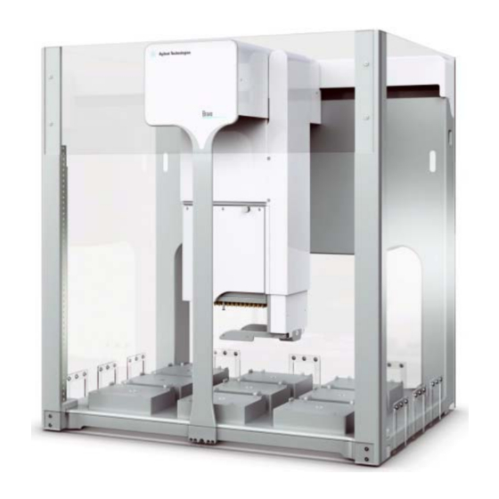
Bravo Platform
Quick Guide
This guide contains the following topics:
•
"About this guide" on page 2
•
"Safety guidelines" on page 3
•
"Hardware components and axes of motion" on page 4
•
"Starting up and shutting down" on page 8
•
"Running a protocol" on page 9
•
"Stopping or pausing a run" on page 11
•
"Using Bravo Diagnostics to control the device" on page 13
•
"Changing the Bravo head" on page 17
Original Instructions
Advertisement

Related Manuals for Agilent Technologies Bravo Platform


Summary of Contents for Agilent Technologies Bravo Platform
-
Page 1: Table Of Contents
Bravo Platform Quick Guide This guide contains the following topics: • “About this guide” on page 2 • “Safety guidelines” on page 3 • “Hardware components and axes of motion” on page 4 • “Starting up and shutting down” on page 8 •... -
Page 2: About This Guide
This guide summarizes the operator instructions in the Bravo Platform User Guide. This guide assumes the following: • The Bravo Platform is installed correctly. For details, see the Bravo Platform Safety and Installation Guide. • The device profile for the specific Bravo configuration is already created and the teachpoints are already set. -
Page 3: Safety Guidelines
Safety label locations on Bravo Platform (front view) Bravo The Bravo Platform has moving parts that are accessible at the front, sides, and rear of the device, if not protected by the Bravo light curtain and shields. For a description of the moving parts, see “Axes of motion”... -
Page 4: Hardware Components And Axes Of Motion
Bravo Item Feature Description Indicator The two light panels that display color-coded status of the Bravo Platform: lights • (solid blue). The Bravo Platform is turned on and in standby mode. • (flashing green). The software is running a protocol on the Bravo Platform. - Page 5 Bravo deck whenever the head moves to a deck location. Deck The area that is accessible by the liquid-handling head. The nine labware locations are numbered 1–3 (back row), 4–6 (middle row), and 7–9 (front row). Figure Nine deck locations for labware (top view) Bravo Platform Quick Guide...
- Page 6 Safety and Installation Guide. Axes of motion The following figures and table show the Bravo moving parts. The Bravo light curtain and shields prevent operator access to moving-parts hazards. Figure Bravo Platform primary axes of motion 00232 Bravo Pinch Hazard Item Part...
- Page 7 The head mount raises and lowers the liquid- handling head. If the Bravo Platform is fitted with a gripper, the gripper moves with the Bravo head. In addition, the gripper has the following axes of motion: •...
-
Page 8: Starting Up And Shutting Down
The following procedures describe how to start up and shut down the Bravo Platform when you are operating it as a standalone device. For instructions on how to turn on and turn off the Bravo Platform when it is integrated into a workstation or system, see the workstation or system user documentation. -
Page 9: Running A Protocol
The waste bins or bottles are empty. If the Bravo Platform is equipped with a Pump Module, the pumps should be primed before the first run of the day to ensure that the tubing from the source bottle is filled. - Page 10 Bravo Platform to the cap connector. Empty the waste container, replace the cap, and attach the fluid line that pumps away from the Bravo Platform to the cap connector. For connection details, see the Pump Module User Guide.
-
Page 11: Stopping Or Pausing A Run
Ensure that no object is interrupting the Light Curtain. In the Bravo Error dialog box, click Retry. The Bravo Platform will attempt to resume the run where it left off. To abort the run after an emergency stop: In the Bravo Error dialog box, click Abort. - Page 12 To resume the run, click Continue in the Scheduler Paused dialog box. To abort a run: In the VWorks window, click Pause all. In the Scheduler Paused dialog box, click Abort process. Bravo Platform Quick Guide...
-
Page 13: Using Bravo Diagnostics To Control The Device
Using Bravo Diagnostics to control the device Using Bravo Diagnostics to control the device To control the Bravo Platform when you are not running a protocol, you use Bravo Diagnostics. For example, you can use Bravo Diagnostics to run a single task, such as to eject tips, to open and close the gripper, and to change the pipette head. - Page 14 Profile name list. Verify that the selected Head type matches the installed head. For example, if a Series III pipette head is installed, the Bravo Platform requires a profile for the Series III head type.
- Page 15 In the Location list, select the deck location of the labware that you placed on the deck. Alternatively, click the location in the graphical display. In the Labware at selected location list, select the type of labware. If the task involves two locations, repeat this step for the second location. Bravo Platform Quick Guide...
- Page 16 Well Selection and Head Mode area. Click a representative well in the plate graphic to select the corresponding quadrant of wells. The selection appears below the plate graphic. Bravo Platform Quick Guide...
-
Page 17: Changing The Bravo Head
For instructions on how to change the 96AM Head, see the AssayMAP Bravo Platform Getting Started Guide. Always turn off the Bravo Platform before removing a head. Failure to turn off the C AU T I O N Bravo Platform before changing the head can damage the head electronics. - Page 18 Changing the Bravo head Changing the mounted head To uninstall the mounted Bravo head: On the side of the Bravo Platform, press the power switch to the off (O) position. Bravo Bravo Make sure that the head mount is at its home position above deck location 5, as the preceding figure shows.
- Page 19 • Pin Tools. Rest the top of the head on a clean, dry surface with the pins facing up. Slide the stand onto the head. Store the head top-side up and resting in the head stand. Bravo Platform Quick Guide...
- Page 20 Changing the Bravo head To install a Bravo liquid-handling head: Make sure that the Bravo Platform is turned off and that the Bravo head mount is in its home position, which is centered above deck location 5. While the head remains seated in the head stand, pull out and twist the two head- retainer pins one-quarter turn so that they remain retracted.
- Page 21 Attempt to rotate the pins to ensure that they are in the locked position. The pins should not rotate freely. Figure Installed head: ( ) retainer pin and ( ) head lock Bravo Platform Quick Guide...
- Page 22 In the VWorks window, ensure that simulation is off and the correct device file (*.dev) is open. In the Devices area, highlight the device name, and then ensure that the profile selected under Agilent Bravo Properties is correct. Bravo Platform Quick Guide...
- Page 23 If the device file contains more than one device profile for the same Bravo Platform, ensure that you disable the unused devices in the device file. For details, see the VWorks Automation Control User Guide. To initialize the Bravo Platform, click Initialize selected devices or Initialize all devices. Bravo Platform Quick Guide...
- Page 24 © Agilent Technologies, Inc. 2019 September 2019 *SD-V1000642* SD-V1000642 Revision B...