
Subscribe to Our Youtube Channel
Related Manuals for YOKOGAWA 701957


Summary of Contents for YOKOGAWA 701957
- Page 1 User’s Model 701957 Bridge Head Manual (DSUB-120 , Shunt CAL, Ω Enhanced Shield) Model 701958 Bridge Head (DSUB-350 , Shunt CAL, Ω Enhanced Shield) IM 701957-01E 2nd Edition...
-
Page 2: Foreword
However, should you have any questions or find any errors, please contact your nearest YOKOGAWA dealer as listed on the back cover of this manual. • Copying or reproducing all or any part of the contents of this manual without YOKOGAWA’s permission is strictly prohibited. -
Page 3: Checking The Contents Of The Package
When contacting the dealer from which you purchased the device, please quote this number. Standard Accessories D-Sub cable Attaching Plate This User’ Manual (for 701957, 701958) B9947KR B8023WP 2 Binding screws Length: 5 m (M4 × 5 mm) IM 701957-01E... -
Page 4: Conventions Used In This Manual And On The Device
Conventions Used in this Manual and on the Device Symbols Used on the Device GND terminal The operator must refer to an explanation in the User’s Manual. Symbols Used in this Manual Note Provides important information for the proper operation of the device. IM 701957-01E... -
Page 5: Table Of Contents
Construction of the Device ....................5 Shunt Calibration ........................ 7 Connecting the Strain Gauge ....................8 Fixing the Device in Place ....................10 Connecting to the Strain Instrument ................. 11 Calibrating Using a Shunt Resistor ................... 12 Specifications ........................16 IM 701957-01E... -
Page 6: Construction Of The Device
Shuntcal–(Shunt signal–) numbers. Shuntcal+(Shunt signal +) The numbers inside are the pin Sense+ (Sensing of the bridge voltage+) numbers of the connector. Bridge– (Bridge voltage –) Input– (Measurement signal –) Input+ (Measurement signal +) Bridge+ (Bridge voltage +) IM 701957-01E... - Page 7 The circuit diagram below shows the bridge head connected to a measuring instrument (the DL750). Isolate the strain gauge before use. CAUTION Do not connect the strain gauge terminal to any items with electric potential. Measurement instrument (example: DL750) Bridge Head 701957/701958 (with shunt calibration support) Sense+ Module B8023WP Sense-...
-
Page 8: Shunt Calibration
Bridge voltage Bridge- For specific instructions on performing shunt calibration, refer to your measuring instrument’s user’s manual. For information on shunt resistance and the corresponding strain values, see page 13 in “Calculation of the Shunt Resistance.” IM 701957-01E... -
Page 9: Connecting The Strain Gauge
Single-gauge Three-wire Method Bridge head terminal Strain gauge Strain gauge Bridge+ (Sense+) Bridge+ Sense+ Input- (Shuntcal-) Shunt Bridge- (Sense-) resistor Input- Input+ Input+ Shuntcal+ Shuntcal- 1 2 3 4 5 Bridge- Switch setting of Sense- Shuntcal the bridge head ON/OFF IM 701957-01E... - Page 10 Four-gauge Method Bridge head terminal Bridge+ Strain gauge Sense+ Bridge+ (Sense+) Strain gauge Strain gauge Input- (Shuntcal-) Bridge- (Sense-) Input+ Input- Input+ 1 2 3 4 5 Strain gauge Bridge- Strain gauge Switch setting of Sense- the bridge head IM 701957-01E...
-
Page 11: Fixing The Device In Place
Align the small holes on the bottom side of the bridge head to the small projections of the attaching plate. Screw the bridge head and the attaching plate together using the accessory binding screws (M4 × 5 mm). Bridge head Attaching Projections plate B9947KR Binding screws (M4 x 5mm) IM 701957-01E... -
Page 12: Connecting To The Strain Instrument
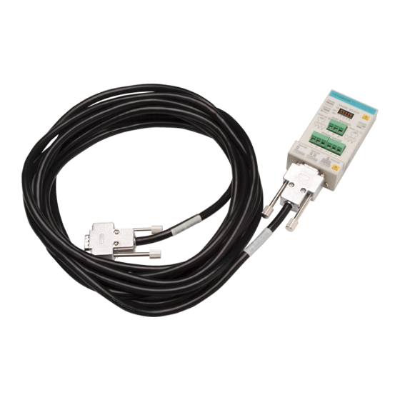
Connecting to the Strain Instrument The bridge head uses a D-Sub 9-pin connector. The accessory cable, B8023WP, is used to connect to the strain instrument. Bridge head Strain instrument Accessory cable B8023WP IM 701957-01E... -
Page 13: Calibrating Using A Shunt Resistor
Calibrating Using a Shunt Resistor Shunt calibration can be performed by combining with the YOKOGAWA's strain module (Model 701271 (STRAIN_DSUB) that supports shunt calibration. Connection procedures for the shunt resistor The following two connection methods are available. In normal cases, connect the resistor in correcting the gain on the negative side. - Page 14 (Equation A): General equation used to calculate the shunt resistance (includes error) Strain (strain you wish to generate when the shunt resistance is turned ON) ε: K: Gauge factor R: Bridge resistance ∆R: Resistance change Rs: Shunt resistance (shunt resistance you wish to derive) IM 701957-01E...
- Page 15 (Equation B): Detailed equation used to calculate the shunt resistance (no error) Bridge voltage Bridge output voltage to R Bridge resistance (except, R Shunt resistance (shunt resistance you wish to derive) Combined resistance when the relay is turned ON (R'=R//Rs) E (Bridge power supply) IM 701957-01E...
- Page 16 For the procedures related to performing the shunt CAL, see the manual that came with the strain module that you are using. Shunt CAL may not operate correctly on some strain measurement instruments. Check this with the manual that came with the strain measurement instrument. IM 701957-01E...
-
Page 17: Specifications
Specifications Bridge resistance Model 701957: 120 Ω Model 701958: 350 Ω Applicable gauge methods Single-gauge Single-gauge three-wire Adjacent-side two-gauge Opposed-side two-gauge Opposed-side two-gauge three-wire Four-gauge Operating conditions Temperature: 5 to 40°C Humidity: 20 to 85% RH External dimensions Approx. 50(W) × 101(H) × 29(D) mm Weight Approx. - Page 18 7 Specifications External drawings Bridge head Attaching plate IM 701957-01E...
Need help?
Do you have a question about the 701957 and is the answer not in the manual?
Questions and answers