
Related Manuals for NI 9232


Summary of Contents for NI 9232
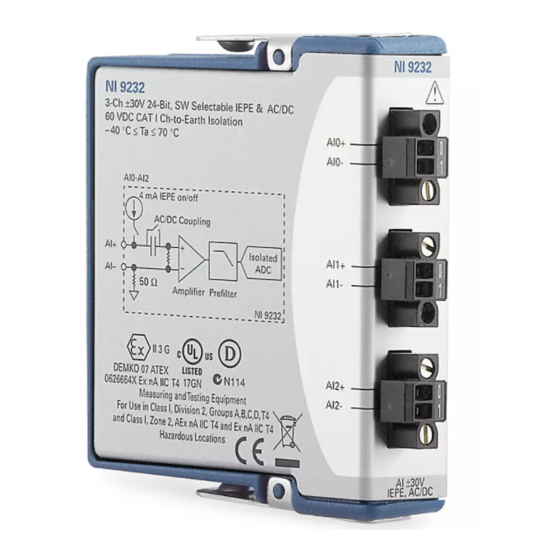
- Page 1 OPERATING INSTRUCTIONS AND SPECIFICATIONS NI 9232 3-Channel, ±30 V, 24-Bit Software Selectable IEPE and AC/DC Analog Input Module Français Deutsch ni.com/manuals...
- Page 2 This document describes how to use the National Instruments 9232 and includes specifications and terminal assignments for the NI 9232. For information about installing, configuring, and programming the system, refer to the system documentation. Visit and enter the following Info Codes: ni.com/info...
-
Page 3: Safety Guidelines For Hazardous Locations
Instruments for repair. Safety Guidelines for Hazardous Locations The NI 9232 is suitable for use in Class I, Division 2, Groups A, B, C, D, T4 hazardous locations; Class I, Zone 2, AEx nA IIC T4, and Ex nA IIC T4 hazardous locations; and nonhazardous locations only. - Page 4 AI terminals. The protection device must prevent the AI+ to AI– voltage from exceeding 42 V if there is a transient overvoltage condition. NI 9232 Operating Instructions and Specifications ni.com...
-
Page 5: Electromagnetic Compatibility Guidelines
II 3G and is suitable for use in Zone 2 hazardous locations, in ambient temperatures of –40 °C Ta 70 °C. If you are using the NI 9232 in Gas Group IIC hazardous locations, you must use the device in an NI chassis that has been evaluated as Ex nC IIC T4, EEx nC IIC T4, Ex nA IIC T4, or Ex nL IIC T4 equipment. - Page 6 (National Instruments part number 611461-01) in accordance with the product installation instructions. Electrostatic Discharge (ESD) can damage this Caution product. To prevent damage, use industry-standard ESD prevention measures during installation, maintenance, and operation. NI 9232 Operating Instructions and Specifications ni.com...
-
Page 7: Special Guidelines For Marine Applications
Install a clamp-on ferrite bead (National Instruments part number 611461-01) on the input cables for each channel that you are connecting to on the NI 9232. Refer to Figure 1 for a diagram. © National Instruments Corp. NI 9232 Operating Instructions and Specifications... - Page 8 AI1+ Source AI1– Shield Signal AI2+ Source AI2– NI 9232 Figure 1. NI 9232 Cable Connections • Clamp-on ferrite beads must be installed on the cable as close to the module as possible. NI 9232 Operating Instructions and Specifications ni.com...
- Page 9 Connecting the NI 9232 The NI 9232 has three 2-terminal detachable screw-terminal connectors that provide connections to three simultaneously sampled analog input channels. AI0+ AI0– AI1+ AI1– AI2+ AI2– Figure 2. NI 9232 Terminal Assignments © National Instruments Corp. NI 9232 Operating Instructions and Specifications...
- Page 10 NI 9232. If you make a ground-referenced connection between the signal source and the NI 9232, make sure the voltage on the AI+ and AI– connections are in the channel-to-earth safety voltage range to ensure proper operation of the NI 9232. Refer to the...
- Page 11 Source AI– – NI 9232 Common Mode Voltage Figure 3. Connecting a Grounded Signal Source to the NI 9232 Signal Source AI– – NI 9232 Figure 4. Connecting a Floating Signal Source to the NI 9232 © National Instruments Corp.
- Page 12 The NI 9232 can also provide an IEPE excitation current for each channel to measure IEPE sensors. Typical IEPE sensors have a case that is electrically isolated from the IEPE electronics, so connecting the sensor to the NI 9232 results in a floating connection even though the case of the sensor is grounded.
-
Page 13: Wiring For High-Vibration Applications
Bias Prefilter 50 Ω Current NI 9232 Figure 5. NI 9232 Input Circuitry for One Channel The NI 9232 also has TEDS circuitry. For more information about TEDS, go to and enter ni.com/info rdteds Wiring for High-Vibration Applications If an application is subject to high vibration, National Instruments... - Page 14 Refer to Figure 7 for an illustration of the NI 9971 backshell. Figure 6. 2-Terminal Detachable Screw-Terminal Connector with Ferrule Figure 7. NI 9971 Backshell NI 9232 Operating Instructions and Specifications ni.com...
- Page 15 The small amount of variation in gain with respect to frequency is called the passband flatness. The digital filters of the NI 9232 adjust the frequency range of the passband to match the © National Instruments Corp. NI 9232 Operating Instructions and Specifications...
- Page 16 Figure 8 shows typical passband flatness for the NI 9232. 0.10 0.08 0.06 0.04 0.02 0.00 –0.02 –0.04 –0.06 –0.08 –0.10 Frequency/Data Rate Figure 8. NI 9232 Typical Passband Flatness NI 9232 Operating Instructions and Specifications ni.com...
-
Page 17: Alias-Free Bandwidth
Alias-Free Bandwidth Any signal that appears in the alias-free bandwidth of the NI 9232 is not an aliased artifact of signals at a higher frequency. The alias-free bandwidth is defined by the ability of the digital filter to reject frequencies above the stopband frequency, and it is equal to the data rate minus the stopband frequency. - Page 18 The frequency of a master timebase ( f ) controls the data rate ( f of the NI 9232. The NI 9232 includes an internal master timebase with a frequency of 13.1072 MHz. When using the internal master timebase, the result is data rates of 102.4 kS/s, 51.2 kS/s, 25.6 kS/s, 17.067 kS/s, and so on down to 0.98 kS/s, depending on the...
- Page 19 102.40 9.31 4.88 51.20 8.53 4.65 34.13 7.88 4.45 25.60 7.31 4.27 20.48 6.83 4.10 17.07 6.40 3.94 14.63 6.02 3.66 12.80 5.69 3.41 11.38 5.39 3.20 10.24 5.12 3.01 © National Instruments Corp. NI 9232 Operating Instructions and Specifications...
- Page 20 Decimation (kS/s) Rate (kS/s) Rate (kS/s) Rate 2.84 1.97 1.22 2.69 1.83 1.16 2.56 1.71 1.11 2.44 1.60 1.07 2.33 1.51 1.02 2.23 1.42 0.98 2.13 1.35 — — 2.05 1.28 — — NI 9232 Operating Instructions and Specifications ni.com...
- Page 21 When using an external timebase with a frequency other than 13.1072 MHz, the NI 9232 has a different set of data rates. Refer to the software help for information about configuring the master timebase source for the NI 9232.
-
Page 22: Sleep Mode
In sleep mode, the system consumes minimal power and may dissipate less heat than it does in normal mode. Refer to the Specifications section for more information about power consumption and thermal dissipation. NI 9232 Operating Instructions and Specifications ni.com... -
Page 23: Specifications
Internal master timebase ( f Frequency ........13.1072 MHz Accuracy........±100 ppm Data rate range ( f ) using internal master timebase Minimum ........0.985 kS/s Maximum ........102.4 kS/s © National Instruments Corp. NI 9232 Operating Instructions and Specifications... - Page 24 –3 dB .......... 0.1 Hz –0.1 dB........0.87 Hz max The data rate must remain within the appropriate data rate range. Refer to the Understanding NI 9232 Data Rates section for more information. NI 9232 Operating Instructions and Specifications ni.com...
- Page 25 AC cutoff frequency response –0.5 –1.0 –1.5 –2.0 –2.5 –3.0 10.0 Frequency (Hz) © National Instruments Corp. NI 9232 Operating Instructions and Specifications...
- Page 26 IEPE excitation current (software-selectable on/off) Minimum ........4 mA Typical ........4.25 mA IEPE excitation noise......100 nA The DC + AC voltage must be below the overvoltage protection of the NI 9232. NI 9232 Operating Instructions and Specifications ni.com...
- Page 27 ......±45 V Refer to the software help for information on reading the IEPE fault detection status. Visit ni.com/info and enter cseriesdoc for information about C Series documentation. © National Instruments Corp. NI 9232 Operating Instructions and Specifications...
- Page 28 Uncalibrated max (–40 °C to 70 °C) ±1.50% ±0.59% Uncalibrated typ (23 °C ±5 °C) ±0.40% ±0.12% Range = 31.5 V † DC coupled Stability Gain drift ........±25 ppm/°C Offset drift (DC coupled) ... ±320 V/°C NI 9232 Operating Instructions and Specifications ni.com...
- Page 29 ) + 0.045° + (360° · f Passband frequency......0.4 · f Flatness (peak-to-peak) Frequency Band 20 Hz to 20.48 kHz 20 Hz to 40.96 kHz typical 70 mdB 75 mdB maximum 75 mdB 100 mdB © National Instruments Corp. NI 9232 Operating Instructions and Specifications...
- Page 30 = 102.4 kS/s......120 dB @ 6.554 MHz Crosstalk ( f = 1 kHz)...... –125 dB Refer to the Understanding NI 9232 Data Rates section for information regarding oversample rates. Rejection of analog prefilter at oversample rate. NI 9232 Operating Instructions and Specifications ni.com...
- Page 31 Dynamic range ( f = 1 kHz, –60 dBFS) Data Rate 102.4 kS/s 51.2 kS/s 25.6 kS/s AC coupled 99 dBFS 102 dBFS 105 dBFS DC coupled 100 dBFS 103 dBFS 106 dBFS © National Instruments Corp. NI 9232 Operating Instructions and Specifications...
- Page 32 Intermodulation distortion (–10.5424 dBFS) DIN 250 Hz/8 kHz 4:1 amplitude ratio ..... –80 dB CCIF 11 kHz/12 kHz 1:1 amplitude ratio ..... –100 dB MTBF ..........Contact NI for Bellcore MTBF or MIL-HDBK-217F specifications. NI 9232 Operating Instructions and Specifications ni.com...
-
Page 33: Power Requirements
(0.28 in.) of insulation stripped from the end Torque for screw terminals ....0.22 N · m to 0.25 N · m (1.95 lb · in. to 2.21 lb · in.) © National Instruments Corp. NI 9232 Operating Instructions and Specifications... - Page 34 Between any two terminals....±45 V max Isolation Channel-to-channel ....None Channel-to-earth ground Continuous ......60 VDC, Measurement Category I Withstand ......1,000 V , verified by a 5 s dielectric withstand test NI 9232 Operating Instructions and Specifications ni.com...
- Page 35 Such voltage measurements include signal levels, special equipment, limited-energy parts of equipment, circuits powered by regulated low-voltage sources, and electronics. Do not connect the NI 9232 to signals or use Caution for measurements within Measurement Categories II, III, or IV.
-
Page 36: Electromagnetic Compatibility
• EN 55011 (CISPR 11): Group 1, Class A emissions • AS/NZS CISPR 11: Group 1, Class A emissions • FCC 47 CFR Part 15B: Class A emissions • ICES-001: Class A emissions NI 9232 Operating Instructions and Specifications ni.com... -
Page 37: Online Product Certification
To obtain product certifications and the Declaration of Conformity (DoC) for this product, visit , search by ni.com/certification module number or product line, and click the appropriate link in the Certification column. © National Instruments Corp. NI 9232 Operating Instructions and Specifications... -
Page 38: Shock And Vibration
Shock and Vibration To meet these specifications, you must panel mount the system and either affix ferrules to the ends of the terminal wires or use the NI 9971 backshell kit to protect the connections. Operating vibration Random (IEC 60068-2-64)..5 g , 10 Hz to 500 Hz Sinusoidal (IEC 60068-2-6) .. -
Page 39: Environmental Management
Maximum altitude......2,000 m Indoor use only. Environmental Management NI is committed to designing and manufacturing products in an environmentally responsible manner. NI recognizes that eliminating certain hazardous substances from our products is beneficial to the environment and to NI customers. -
Page 40: Waste Electrical And Electronic Equipment (Weee)
(For information ni.com/environment/rohs_china about China RoHS compliance, go to ni.com/ environment/rohs_china Calibration You can obtain the calibration certificate and information about calibration services for the NI 9232 at ni.com/calibration Calibration interval ......1 year NI 9232 Operating Instructions and Specifications ni.com... -
Page 41: Where To Go For Support
United States, visit the Worldwide Offices section of to access the branch office ni.com/niglobal Web sites, which provide up-to-date contact information, support phone numbers, email addresses, and current events. © National Instruments Corp. NI 9232 Operating Instructions and Specifications... - Page 42 LabVIEW, National Instruments, NI, ni.com, the National Instruments corporate logo, and the Eagle logo are trademarks of National Instruments Corporation. Refer to the Trademark Information at ni.com/trademarks for other National Instruments trademarks. Other product and company names mentioned herein are trademarks or trade names of their respective companies.
Need help?
Do you have a question about the 9232 and is the answer not in the manual?
Questions and answers