
Related Manuals for Qsonica Sonicator Q500


Summary of Contents for Qsonica Sonicator Q500
- Page 1 Sonicator ULTRASONIC PROCESSOR Part No. Q500 OPERATION MANUAL Qsonica, LLC. 53 Church Hill Rd. Newtown, CT 06470 USA Phone: 203.426.0101 Fax: 203.426.7026 info@sonicator.com www.sonicator.com Rev. 8-20...
- Page 2 Page 2 of 30...
-
Page 3: Table Of Contents
Table of Contents WARRANTY ......................4 WARNINGS ......................5 SPECIFICATIONS ....................6 PRINICPLES OF OPERATION ................8 DESCRIPTION OF COMPONENTS / FUNCTIONS OF CONTROLS ....10 5.1. Q500 FRONT PANEL ..................10 5.2. Q500 REAR PANEL ..................10 5.3. CONVERTER CLAMPING ................11 5.4. -
Page 4: Warranty
WARRANTY Your Ultrasonic Processor is warranted and backed by the manufacturer for a period of two years from the date of shipment against defects in material and workmanship under normal use as described in this instruction manual. During the warranty period, the manufacturer will, at its option, as the exclusive remedy, either repair or replace without charge for material and labor, the part(s) which prove to be defective, provided the unit is returned to us properly packed with all transportation charges prepaid. -
Page 5: Warnings
2. WARNINGS Please read the manual in its entirety. Necessary instruction and guidance are provided to help ensure the successful operation of this device. Observe the following: High voltage is present in the power supply, converter and high frequency cable. There are no user-serviceable parts inside any of these devices. -
Page 6: Specifications
3. SPECIFICATIONS Power Supply Input Voltage 100 VAC – 132 VAC @ 50/60 Hz 198 VAC – 264 VAC @ 50/60 Hz Rated Current 10 Amps max. 6.3 Amps max. Fuse Rating 12 Amps Slow Blow 6.3 Amps Slow Blow Weight 16 lbs. - Page 7 Environmental Pollution Degree Installation Category Temperature: 41 - 104ºF (5 - 40ºC) Relative Humidity 10 - 95% (Non Condensing) Operating Limits Altitude: 6,651 ft. (2000 m) Temperature: 35 -120 F (2 - 49 Relative Humidity 10 - 95% (Non Condensing) Shipping/Storage Ambient Pressure Extremes: 40,000 ft.
-
Page 8: Prinicples Of Operation
4. PRINCIPLES OF OPERATION The ultrasonic electronic power supply transforms AC line power to a 20 KHz signal that drives a piezoelectric converter/transducer. This electrical signal is converted by the transducer to a mechanical vibration due to the characteristics of the internal piezoelectric crystals. The vibration is amplified and transmitted down the length of the horn/probe where the tip longitudinally expands and contracts. - Page 9 increases (increased load on the probe), additional power will be delivered by the power supply to ensure that the excursion at the probe tip remains constant. The displayed wattage readings will vary as the load changes, however the amplitude will remain the same. The resistance to the movement of the probe determines how much power will be delivered to maintain amplitude.
-
Page 10: Description Of Components / Functions Of Controls
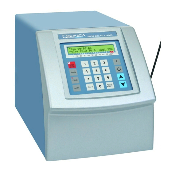
5. DESCRIPTION OF COMPONENTS / FUNCTIONS OF CONTROLS Q500 FRONT PANEL Converter Cable Converter Power Supply ½” Probe with Replaceable tip (#4220) Lab Stand with Clamp (sold separately) Q500 REAR PANEL 9 Pin Connector Cooling Fan Foot Switch Jack Converter Cable Connector Fuses... -
Page 11: Converter Clamping
CONVERTER CLAMPING Improper clamping can damage the system and void the warranty. Using a sound enclosure (part #432B2) or stand (part #459) will ensure a proper fit. Proper Clamping Improper Clamping Page 11 of 30... -
Page 12: Functions Of Keys, Controls, Indicators And Connectors
5.4 FUNCTIONS OF KEYS, CONTROLS, INDICATORS AND CONNECTORS FRONT PANEL Displays prompts and control parameters including: • Amplitude selected • Output power delivered to the probe in watts • Selected duration of processing • Actual processing time LCD display • Elapsed time •... - Page 13 Used with the AMPL key when the unit is on stand-by to set the amplitude of vibration at the probe tip. Also used to increase or ▲ ▼ decrease the amplitude in small increments while the unit is running. To accomplish this task, depress the ENTER/REVIEW key twice to display AMPLITUDE CONTROL, then depress the ▲...
-
Page 14: Preparation For Use
6. PREPARATION FOR USE Inspection Prior to installing the ultrasonic processor, perform a visual inspection to detect any evidence of damage, which might have occurred during shipment. Before disposing of any packaging material, check it carefully for small items. The ultrasonic processor was carefully packed and thoroughly inspected before leaving our factory. -
Page 15: Operating Instructions
7. OPERATING INSTRUCTIONS 7.1 CAUTION Do not operate the power supply unless it is connected to the converter. Never allow liquid to spill into the converter. Do not allow a Microtip to vibrate in air. Do not allow the vibrating Microtip to contact anything but the sample. ... -
Page 16: Setup
7.2. SETUP 1. Connect the power cord into the receptacle on the rear of the ultrasonic processor. 2. Make sure the unit is switched off. Plug the electrical line cord into the electrical outlet. 3. If the optional foot switch is used, insert the plug into the jack located on the rear panel. 4. -
Page 17: Operation
7.3. OPERATION START UP: Press the ON key. The screen will display the power rating of the Ultrasonic Processor and the following control parameters. - : --: -- Time -- -- Pulse Ampl -- % AMPLITUDE: Desired amplitude must be set in order for the Ultrasonic Processor to be operational. - Page 18 3. To increase or decrease the amplitude in small increments when the ultrasonics is on, depress the AMPL to display Amplitude Setting on the screen, then depress the ▲ or ▼ key, as required. Since the amplitude required is application dependent and subject to the volume and composition of the sample, it is recommended that the amplitude be selected through experimentation, by increasing or decreasing the level of intensity as needed to properly process the sample to achieve desired results.
- Page 19 2. Using the numeric keys, set the ON portion of the cycle, then press the ENTER/REVIEW key. The screen will display: Pulse on 10 sec Pulse off __ sec 3. Using the numeric keys set the OFF portion of the cycle, then press the ENTER/REVIEW key. The screen will display: Pulse on 10 sec Pulse off 10 sec...
-
Page 20: Techniques For Optimizing Results
The addition of a stir bar can greatly aid processing of large samples. A probe should not be used to process a volume larger than indicated on the chart unless the application is reviewed and approved by a Qsonica representative. - Page 21 How to prevent foaming (small sample issue) Foaming is a problem that often occurs with samples volumes below 1ml. The cause of foaming is generally 3 issues: amplitude is too high for a small volume, tip is too large for the volume, or the tip is not inserted to a proper depth.
-
Page 22: Maintenance
MAINTENANCE It is recommended to periodically inspect the unit, both visually and physically, to insure optimum and safe performance. This inspection should be scheduled as a routine maintenance procedure, done with the unit power OFF and with the unit unplugged from the AC power source. Long exposure to acids or caustics results in corrosion of metal parts or components. -
Page 23: Attaching & Detaching A Probe
9.2. ATTACHING & DETACHING A PROBE Disconnect probe from converter. Use the wrench set provided with the system. Clean threaded stud. Use alcohol and a cotton swab to remove any debris on the threading of the connecting stud. Allow the alcohol to dry completely. Clean threading in converter. -
Page 24: System Cleaning Instructions
Note: When tightening a Microtip the tip must not be in contact with the work surface. Always have the tip extending off of the table or work surface to minimize stress to the tip. Note: For additional information on tightening and removing probes, please visit the Videos section of the Qsonica website. https://www.sonicator.com/pages/videos 9.3. -
Page 25: Troubleshooting
Note: If you touch Start and sonication does not occur, switch Off main power, wait 5 seconds and switch back On. If the problem persists after reviewing each of the 6 items above, please contact Customer Service or complete a repair form on the Qsonica website at: https://www.sonicator.com/pages/troubleshooting-repair Page 25 of 30... -
Page 26: Return Of Equipment
RETURN OF EQUIPMENT It is suggested that an Ultrasonic Processor in need of repair be sent back to the factory. In order to receive prompt service; always contact your Customer Service Representative before returning any instrument. Include date of purchase, model number and serial number. Please obtain a Return Authorization Number prior to returning the instrument. -
Page 27: Safety Certification Form
11.1. SAFETY CERTIFICATION FORM Items being returned: _____________________________________________________________________________ _____________________________________________________________________________ _____________________________________________________________________________ _____________________________________________________________________________ _____________________________________________________________________________ Please check only one item below: ___ The equipment was never used or exposed to any radiological, biological or chemical agents and is safe to handle, use or dispose of. ___ The equipment was used but not in conjunction with or exposed to any radiological, geological or chemical agents and is safe to handle, use, or dispose of. -
Page 28: Addendum
ADDENDUM 12.1. CONVERTER COOLING Continuous sonication will cause both the probe and sample temperature to increase. The heat will transfer up to the converter. If the converter overheats the internal crystals can crack and the entire converter will require replacement. Converter damage due to overheating is not covered under warranty. - Page 29 Step Description Reference Attach a clean, dry, regulated compressed air source to one of the ¼” Air Cooling hose barbs. Note: The compressed air should be dry, oil free and filtered with a 5 micron filter. hose must be attached to the 2 ¼”...
-
Page 30: Cooling Air Regulation And Adjustment
12.2 COOLING AIR REGULATION AND ADJUSTMENT Adjust the regulated compressed air until the gauge indicates 10 ± 1 PSIG (approximately 4 CFM). The compressed air will flow into the converter and out through the outlet barb. Verify the compressed air is flowing out from the exhaust tube upon each use. Example of the air cooling hoses set up properly with the enclosure.
Need help?
Do you have a question about the Sonicator Q500 and is the answer not in the manual?
Questions and answers