
Subscribe to Our Youtube Channel
Related Manuals for Qsonica Sonicator


Summary of Contents for Qsonica Sonicator
- Page 1 Sonicator ULTRASONIC PROCESSOR Part No. Q125 OPERATION MANUAL 53 Church Hill Road, Newtown, CT 06470 U.S.A · Phone: 203.426.0101 1.877.338.9636 Fax: 203.426.7026 · Web: www.sonicator.com E-mail: info@sonicator.com Rev. 3-11...
- Page 2 Rev. 3-11...
-
Page 3: Table Of Contents
Table of Contents Section Page No. Warranty Warnings Specifications Principles of Operation Description of Components / Functions of Controls 10-12 Preparation for Use Operating Instructions 14-17 Maintenance 18-20 Troubleshooting 10. Service / Return of Equipment 11. Service Safety Certification form Rev. -
Page 4: Warranty
1. Warranty Your ultrasonic processor is warranted and backed by the manufacturer for a period of two years from the date of shipment against defects in material and workmanship under normal use as described in this instruction manual. During the warranty period, the manufacturer will, at its option, as the exclusive remedy, either repair or replace without charge for material and labor, the part(s) which prove to be defective, provided the unit is returned to us properly packed with all transportation charges prepaid. -
Page 5: Warnings
The generator must be properly grounded with a 3-prong plug. Test electrical outlet for proper grounding before plugging in unit. Install the Sonicator in an area free from excessive dust, dirt, explosive or corrosive fumes and protected from extremes in temperature and humidity. Do not place the Generator within a Fume Hood. -
Page 6: Specifications
3. Specifications Generator 220 VAC – 240 VAC @ 50/60 Hz Input Voltage 100 VAC – 120 VAC @ 50/60 Hz Rated Current 2.4 Amps max. 1.2 Amps max. Fuse Rating 3 Amps (slo-blo)* 1.6 Amps (slo-blo)* Weight 7 lbs. (3.2 Kg) Dimensions 8"W x13.75"L x 5.75"H 203mm x 349mm x 146mm... - Page 7 Environmental Pollution Degree Installation Category Operating Limits Temperature: 41 - 104ºF (5 - 40ºC) Relative Humidity 10 - 95% (Non Condensing) Altitude: 6,651 ft. (2000 m) Temperature: 35 -120 F (2 - 49 Shipping/Storage Relative Humidity 10 - 95% (Non Condensing) Ambient Pressure Extremes: 40,000 ft.
-
Page 8: Principles Of Operation
4. Principles of Operation The ultrasonic electronic generator transforms AC line power to a 20 KHz signal that drives a piezoelectric converter/transducer. This electrical signal is converted by the transducer to a mechanical vibration due to the characteristics of the internal piezoelectric crystals. The vibration is amplified and transmitted down the length of the horn/probe where the tip longitudinally expands and contracts. - Page 9 increases (increased load on the probe), additional power will be delivered by the power supply to ensure that the excursion at the probe tip remains constant. The displayed wattage readings will vary as the load changes, however the amplitude will remain the same. The resistance to the movement of the probe determines how much power will be delivered to maintain amplitude.
-
Page 10: Description Of Components / Functions Of Controls
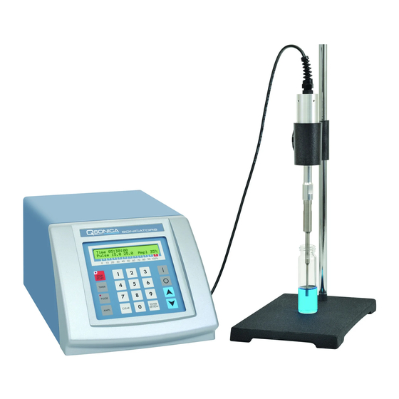
5. Description of Components / Functions of Controls The Model # Q125 includes a standard 1/8” diameter microtip (#4422). Q125 Front Panel Converter Converter Cable 1/8” Microtip Generator Q125 Rear Panel Power Cord Cooling Fan Connector 9 Pin Footswitch Converter Cable Connector Connector Connector... - Page 11 FUNCTIONS OF KEYS, CONTROLS, INDICATORS, AND CONNECTORS FRONT PANEL Displays prompts and the following control parameters: • Amplitude selected LCD display • Amount of output power delivered to the probe in watts, and as a percentage of 125 watts. • Accumulated amount of energy in Joules delivered to the probe.
- Page 12 9-PIN D-SUB CONNECTOR Pin No. Description Not connected Not connected Not connected Enables connection to a frequency counter. Enables connection to an external power monitor (5 mv = 1 watt) Ground Energizes the ultrasonics when connected to ground. Enables the intensity to be remotely adjusted using an external 10k 8 and 9 potentiometer.
-
Page 13: Preparation For Use
6. Preparation for Use (Getting Started) INSPECTION Prior to installing the Ultrasonic Processor, perform a visual inspection to detect any evidence of damage, which might have occurred during shipment. Before disposing of any packaging material, check it carefully for small items. The Ultrasonic Processor was carefully packed and thoroughly inspected before leaving our factory. -
Page 14: Operating Instructions
7. Operating Instructions CAUTION Do not operate the power supply unless it is connected to the converter. • Never allow liquid to spill into the converter. • Do not allow a microtip to vibrate in air for more than 10 seconds. •... - Page 15 NOTE: To clear an incorrect entry press the CLEAR key. 1. Immerse the microtip half way into the sample. If the probe is immersed to an insufficient depth, air will be injected into the sample, causing the sample to foam. Also ensure that the probe tip is not touching the wall of the sample vessel as it may be damaged and it will not vibrate properly.
- Page 16 PULSER: Ultrasonics generates heat. Pulsing ultrasonics on and off helps to prevent heat build up in temperature sensitive samples. In addition, pulsing enhances processing by allowing the material to settle back under the probe after each burst. The ON and OFF pulse duration can be set independently from 01 second to 59 seconds.
- Page 17 REVIEW: The REVIEW function provides a “window” on the process by displaying various operating parameters without process interruption. Pressing the ENTER/REVIEW key repeatedly during processing will consecutively display the following information. a) Selected amplitude: e.g. Amplitude 40% b) Selected processing time and elapsed processing time: e.g.
-
Page 18: Maintenance
8. Maintenance It is recommended to periodically inspect the unit, both visually and physically, to insure optimum and safe performance. This inspection should be scheduled as a routine maintenance procedure, done with the unit power OFF and with the unit unplugged from the AC power source. Long exposure to acids or caustics results in corrosion of metal parts or components. - Page 19 Follow the steps below for attaching and detaching microtip probes: Disconnect probe from convertor. Use the wrench set provided with the system. Clean threaded stud. Use alcohol and a cotton swab to remove any debris on the threading of the connecting stud. Allow the alcohol to dry completely. 3.
-
Page 20: Troubleshooting
System Cleaning Instructions The generator and converter may be cleaned using an acid-free cleaning solution (i.e. glass cleaner). Probes should be cleaned using isopropyl alcohol. Probes are made from titanium and can be autoclaved (the converter is an electrical part and cannot be sterilized in this manner). Before each procedure place the probe tip in water or alcohol and turn the power on for a few seconds to remove residue. -
Page 21: Service / Return Of Equipment
10. Return of Equipment It is suggested that an Ultrasonic Processor in need of repair be sent back to the factory. In order to receive prompt service; always contact your Customer Service Representative before returning any instrument. Include date of purchase, model number and serial number. Please obtain a Return Authorization Number prior to returning the instrument. -
Page 22: Service Safety Certification Form
SAFETY CERTIFICATION FORM Items being returned: ______________________________________________________________________ ______________________________________________________________________ ______________________________________________________________________ ______________________________________________________________________ ______________________________________________________________________ ______________________________ Please check only one item below: ___ The equipment was never used or exposed to any radiological, biological or chemical agents and is safe to handle, use or dispose of. ___ The equipment was used but not in conjunction with or exposed to any radiological, geological or chemical agents and is safe to handle, use, or dispose of.
Need help?
Do you have a question about the Sonicator and is the answer not in the manual?
Questions and answers