
Related Manuals for Qsonica Sonicator Q700


Summary of Contents for Qsonica Sonicator Q700
- Page 1 Sonicator ULTRASONIC PROCESSOR Part No. Q700 OPERATION MANUAL Qsonica, LLC. 53 Church Hill Rd. Newtown, CT 06470 USA Phone: 203.426.0101 Fax: 203.426.7026 info@sonicator.com www.sonicator.com Rev. 9-16...
- Page 2 Table of Contents Section Page No. Warranty Warnings Specifications Principles of Operation Description of Components / Functions of Controls 9-12 Preparation for Use Operating Instructions (Getting Started) 14-23 Maintenance 24-26 Troubleshooting Service / Return of Equipment Service Safety Certification form Addendum 30-32 Rev.
-
Page 3: Warranty
1. Warranty Your Ultrasonic Processor is warranted and backed by the manufacturer for a period of two years from the date of shipment against defects in material and workmanship under normal use as described in this instruction manual. During the warranty period, the manufacturer will, at its option, as the exclusive remedy, either repair or replace without charge for material and labor, the part(s) which prove to be defective, provided the unit is returned to us properly packed with all transportation charges prepaid. -
Page 4: Warnings
2. Warnings Please read the manual in its entirety. Necessary instruction and guidance are provided to help ensure the successful operation of this device. Your new Ultrasonic Liquid Processor has been designed, built and tested to assure maximum operator safety. However, no design can completely protect against improper use that may lead to bodily injury and/or property damage. -
Page 5: Specifications
3. Specifications Generator 220 VAC – 240 VAC @ 50/60 Hz Input Voltage 100 VAC – 120 VAC @ 50/60 Hz Rated Current 12 Amps max. 6 Amps max. Fuse Rating 15 Amps* 8 Amps* Weight 16 lbs. (7.3 Kg) Dimensions 8"W x 15.25"L x 8.5"H 203 mm x 387 mm x 216 mm... - Page 6 Environmental Pollution Degree Installation Category Operating Limits Temperature: 41 - 104ºF (5 - 40ºC) Relative Humidity 10 - 95% (Non Condensing) Altitude: 6,651 ft. (2000 m) Temperature: 35 -120 F (2 - 49 Shipping/Storage Relative Humidity 10 - 95% (Non Condensing) Ambient Pressure Extremes: 40,000 ft.
-
Page 7: Principles Of Operation
4. Principles of Operation The ultrasonic electronic generator transforms AC line power to a 20 KHz signal that drives a piezoelectric converter/transducer. This electrical signal is converted by the transducer to a mechanical vibration due to the characteristics of the internal piezoelectric crystals. The vibration is amplified and transmitted down the length of the horn/probe where the tip longitudinally expands and contracts. - Page 8 The AMPLITUDE control allows the ultrasonic vibrations at the probe tip to be set to any desired level. Although the degree of cavitation/ultrasonic energy required to process the sample can readily be determined by visual observation, the amount of power required cannot be predetermined. A sensing network continuously monitors the output requirements, and automatically adjusts the power to maintain the amplitude at the preselected level.
- Page 9 Note: Improper clamping can damage the system and void the warranty. Correct way to clamp Not correct Note: Using a Qsonica sound enclosure or stand will ensure a proper fit. Rev. 9-16...
-
Page 10: Description Of Components / Functions Of Controls
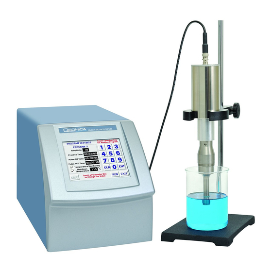
5. Description of Components / Functions of Controls The Model # Q700 includes a standard 1/2” diameter probe (#4220). 5a. Q700 Front Panel Converter Converter Cable Generator ½” Horn/Probe with replaceable tip 5b. Q700 Rear Panel On/Off Switch Cooling Fan Footswitch Jack Temperature Probe... - Page 11 FUNCTIONS OF KEYS, CONTROLS, INDICATORS, AND CONNECTORS FRONT PANEL Displays prompts and control parameters including: • Amplitude selected • Output power delivered to the probe in watts • Selected duration of processing • Actual processing time Touch screen display • Elapsed time •...
- Page 12 REAR PANEL On / Off Switch Turns the power supply on and off. Footswitch Connector Connects to the footswitch cable. Temperature Probe Connects to the Temperature monitoring probe or thermocouple Connector Converter Cable Connects to the converter. Connector (Output) Power Supply Connector Connects to the electrical line cord and encases the fuse(s).
-
Page 13: Preparation For Use
6. Preparation for Use INSPECTION Prior to installing the ultrasonic processor, perform a visual inspection to detect any evidence of damage, which might have occurred during shipment. Before disposing of any packaging material, check it carefully for small items. The ultrasonic processor was carefully packed and thoroughly inspected before leaving our factory. The carrier, upon acceptance of the shipment, assumed responsibility for its safe delivery. -
Page 14: Operating Instructions (Getting Started)
7. Operating Instructions (Getting Started) CAUTION Do not operate the power supply unless it is connected to the converter. • Never allow liquid to spill into the converter. • Do not allow a Microtip to vibrate in air. • Do not allow the vibrating Microtip to contact anything but the sample. •... - Page 15 10. If using a laboratory stand, mount the convertor /probe assembly using a clamp. Be sure to secure the clamp to the upper section of the convertor housing only. Never secure the clamp to any other portion of the convertor/probe assembly. If you are using an acoustic enclosure mount the convertor properly in the convertor collar.
- Page 16 To Manual Mode To Program Menu To Option Screen To Previous Screen This screen allows the user to select Manual mode, Program menu or Options screen. 2. Select the Mode of Operation or access Options screen. a. Manual Mode: Selecting Manual Run allows the user to set the unit output level manually (setting 1 –...
- Page 17 The following screen displays the Manual Mode. A. Microtip Mode – Indicates that the unit is set for use with microtips only. This mode should not be used with standard probes or horns (1/2” or larger). See page 15 for information on selecting YES or NO at the “Are you using a Microtip screen”.
- Page 18 Program Menu The unit can be programmed to sonicate at specific, user-selected time intervals including pulse mode. To Program Sequence 1 Screen Screen To Option Screen Sequence 2 Screen Previous Screen Select/Modify a Program – Create, select or modify up to 10 different programs. Select/Modify Sequence 1 &...
- Page 19 Programming Screen How To Create a Program The ultrasonic processor has the ability to save up to 10 programs. 1. Select a program number from the keypad, the program number will appear above the Amplitude box. For each of the following steps: After touching a field, the background will change to yellow indicating an active field.
- Page 20 How To Run A Saved Program From the program screen (see image at top of previous page), touch the program number on the right side of the screen and the selected program settings will appear. Follow steps 9 and 10 from the previous page. This Run screen is an example of a sample program in progress.
- Page 21 How to Create a Sequence 1. Touch the Program (PGM) field, select the appropriate program number and touch ENT. 2. Enter each desired program number in order, in the PGM fields. 3. If a delay or rest time between programs is desired, touch the Delay After field. Enter the appropriate time frame.
- Page 22 Temperature Units – A temperature probe (Part# 4102 or 4103) is required for use of this option. The Temperature Probe option can be selected if you wish to monitor the temperature of the sample being processed. The temperature probe must be plugged into the back of the ultrasonic processor and the probe tip must be in the liquid sample.
- Page 23 Techniques for Optimizing Results Probe Depth Immerse the probe tip 1.5 times the tip diameter into the solution, without touching the bottom. For example, the ½” horn should be immersed at least ¾” below the liquid surface. Immersion depth must be sufficient to prevent foaming and allow the sample to mix well. If the probe is too deep it will sonicate against the bottom of the vessel and not promote good mixing to affect the sample near the top of the vessel.
-
Page 24: Maintenance
9. Maintenance It is recommended to periodically inspect the unit, both visually and physically, to insure optimum and safe performance. This inspection should be scheduled as a routine maintenance procedure, done with the unit power OFF and with the unit unplugged from the AC power source. Long exposure to acids or caustics results in corrosion of metal parts or components. - Page 25 Follow the steps below for attaching and detaching accessories: Disconnect probe from convertor. Use the wrench set provided with the system. Clean threaded stud. Use alcohol and a cotton swab to remove any debris on the threading of the connecting stud. Allow the alcohol to dry completely. 3.
- Page 26 Replacement Tip Removal Replacement Tip Tightening Replacement Tip Removal Replacement Tip Tightening *Note: When tightening a Microtip the tip must not be in contact with the work surface. Always have the tip extending off of the table or work surface to minimize stress to the tip. System Cleaning Instructions The generator and converter may be cleaned using an acid-free cleaning solution (i.e.
-
Page 27: Troubleshooting
9. Troubleshooting Your Ultrasonic Processor was designed to provide you with years of safe and dependable service. Nevertheless, because of component failure or improper usage, the possibility does exist that it might not perform as it should, shut down or stop working all together. The most probable causes for malfunction are listed below and should be investigated. - Page 28 10. Return of Equipment It is suggested that an Ultrasonic Processor in need of repair be sent back to the factory. In order to receive prompt service; always contact your Customer Service Representative before returning any instrument. Include date of purchase, model number and serial number. Please obtain a Return Authorization Number prior to returning the instrument.
- Page 29 SAFETY CERTIFICATION FORM Items being returned: ________________________________________________________________________ ________________________________________________________________________ ________________________________________________________________________ ________________________________________________________________________ ________________________________________________________________________ ____________________ Please check only one item below: ___ The equipment was never used or exposed to any radiological, biological or chemical agents and is safe to handle, use or dispose of. ___ The equipment was used but not in conjunction with or exposed to any radiological, geological or chemical agents and is safe to handle, use, or dispose of.
-
Page 30: Addendum
Addendum Converter Cooling Continuous sonication will cause both the probe and sample temperature to increase. The heat will transfer up to the converter. If the converter overheats the internal crystals can crack and the entire converter will require replacement. Converter damage due to overheating is not covered under warranty. - Page 31 A probe should not be used to process a volume larger than indicated on the chart unless the application is reviewed and approved by a Qsonica representative. While there is no absolute sample volume range for any probe/horn, below is a general guideline to follow.
- Page 32 100%, the probe will achieve an amplitude of approximately 120µm. At setting 50% the amplitude is approximately 60µm. Note this is approximate and not perfectly linear. Qsonica measures the amplitude of each probe at 100% and these values are published in the brochure.
Need help?
Do you have a question about the Sonicator Q700 and is the answer not in the manual?
Questions and answers