
Subscribe to Our Youtube Channel
Related Manuals for GEA Grasso V Series


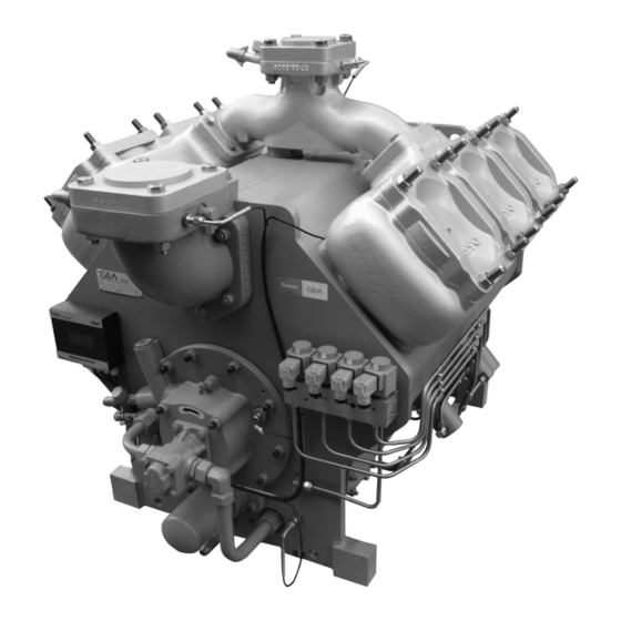
Summary of Contents for GEA Grasso V Series
- Page 1 Reciprocating Compressors for industrial refrigeration GEA Grasso V Installation and Maintenance instructions 0089288gbr_11...
- Page 2 GEA. This restriction also applies to the corresponding drawings and diagrams. LEGAL NOTICE This publication has been written in good faith. However, GEA cannot be held responsible, neither for any errors occurring in this publication nor for their consequences.
- Page 3 SYMBOLS USED Danger Stands for an immediate danger leading to severe physical injuries or death. ► Description for avoiding the danger. Warning! Stands for a potentially dangerous situation leading to severe physical injuries or death. ► Description for avoiding the dangerous situation. Caution! Stands for a potentially dangerous situation which could lead to minor physical injuries or damage to property.
- Page 4 Installer oriented information The compressor (package) is filled with nitrogen to prevent penetration of moisture. Therefore, keep the compressor closed until the compressor (package) is being installed. Warning! The compressor is not filled with oil. Hint! After the successful initial run of the compressor (package) the warranty chart must be filled in and returned to Grasso.
- Page 5 General All documentation can be downloaded via our web site. GEA technical manuals includes “generic paragraphs”; this means that it can occur that not all data as described is relevant for the current compressor series as mentioned in this manual. (For instance, not all compressor series...
- Page 6 0089288gbr_11 30.10.2017...
- Page 7 CYLINDER NUMBERING, BOOSTER AND SINGLE-STAGE OPERATION Cylinder numbering Fig.1: Example cylinder numbering 6 cylinder compressor Booster or single-stage operation Booster operation applies if condensing temperature < +5 Single-stage operation applies if condensing temperature >= +5 0089288gbr_11 30.10.2017...
- Page 8 0089288gbr_11 30.10.2017...
- Page 9 GENERAL INFO Main setup data Value Description Remark Grasso V 300 (T) .. V 600 (T) Grasso V 700 (T) .. V 1800 (T) The NO-solenoid has to be de-energised 20 seconds after starting the compressor Start frequency max. 6 starts per hour motor to enabel the motor to reach the minimum speed and the compressor to develop the...
- Page 10 0089288gbr_11 30.10.2017...
-
Page 11: Table Of Contents
TABLE OF CONTENTS INSTALLATION AND PREPARATION FOR USE Running-in oil filter has to be installed after an overhaul or big repair INSTALLATION 1.2.1 Moving instructions and storage 1.2.2 Storage 1.2.3 Hoisting and moving instructions 1.2.4 Required free space 1.2.5 Foundation requirements Concrete structure Anchoring Mounting the base frame on a concrete block... - Page 12 First maintenance SMS FACTOR Legend Description Maintenance ABC when GMM is applied 3.6.1 Compressor 3.6.2 Package components Grasso V 300 .. 1800 (T), WITHOUT GMM APPENDIX; Product Information (PI) GRASSO MAINTENANCE MONITOR GENERAL LIMITS OF OPERATION GRASSO V STARTING UP OF TWO-STAGE COMPRESSORS DIAGRAMS SINGLE STAGE AND BOOSTER DIAGRAMS TWO STAGE LUBRICATING OILS (choice and recommendations)
-
Page 13: Installation And Preparation For Use
INSTALLATION AND PREPARATION FOR USE Running-in oil filter has to be installed after an overhaul or big repair INSTALLATION AND PREPARATION FOR USE Running-in oil filter has to be installed after an overhaul or big repair Hint! This is why and when the running in oil filters are required: Warning! A running in oil filter has always to be installed after an overhaul or big repair for the 1... -
Page 14: Moving Instructions And Storage
INSTALLATION AND PREPARATION FOR USE INSTALLATION The system should be charged with the correct amount of refrigerant. The oil should be warmed up above minimum start up oil temperature (see "Product Information"). The control cabinet should be energised to check the package controls. Hint! Do not forget to charge the oil separator (if present) initially with oil, to the level of the float assembly... -
Page 15: Required Free Space
INSTALLATION AND PREPARATION FOR USE INSTALLATION Packaged base frame: The only places that can be used for safe hoisting of the package are the four hoisting eyes on the steel base frame as shown in the above figure. Prior to hoisting a compressor package with a V-belt drive arrangement, the factory mounted drive guard has to be removed. -
Page 16: Foundation Requirements
INSTALLATION AND PREPARATION FOR USE INSTALLATION 1.2.5 Foundation requirements Hint! Compressor (package) has to be mounted on a concreted block. On request, Grasso can calculate the exact dimensions of the concrete block, based on the compressor size and operating conditions. This paragraph covers measures to be taken for a compressor (package) mounting on a concrete block. -
Page 17: Anchoring
INSTALLATION AND PREPARATION FOR USE INSTALLATION • The concrete block should be set on firm footings or on a floor capable of carrying the weight of the concrete block and capable of absorbing the free forces and gas forces of the compressor during operation. The ground under the concrete block should be horizontal and flat. -
Page 18: Mounting The Base Frame On A Concrete Block
INSTALLATION AND PREPARATION FOR USE INSTALLATION Fig.6: Anchoring details Drilled chemical anchor (M20) Grouted anchor recesses (M20) Installed chemical anchor before placing the base frame Installing chemical anchor after placing the base frame (base frame cannot be removed easily) Drilling angle 1.2.5.3 Mounting the base frame on a concrete block General After the space between base frame and concrete base has been filled-up with a... -
Page 19: Mounting Bare Compressor On A Concrete Block
INSTALLATION AND PREPARATION FOR USE INSTALLATION Levelling the base frame Fig.7: Grouting details Self-levelling grout Adjusting bolts (4x) Washer Temporary barrier strip around and inside frame Complete cured concrete block Grout layer After the anchor filling mortar has completely cured the frame should be levelled with a space between block and lower frame flange of 3 - 5 mm*. -
Page 20: Connecting To Refrigerating System Pipework
INSTALLATION AND PREPARATION FOR USE INSTALLATION If base frame is not applied the approximately the same procedure of levelling the base frame has to be applied for the bare shaft compressor (refer Section 1.2.5.3, Page 18). The mounting surfaces of the compressor feet must be level without any deviation and projecting at least 10 mm above the concrete base. -
Page 21: Connecting The Power Supply
INSTALLATION AND PREPARATION FOR USE INSTALLATION Suspension of system pipework To eliminate vibration transmission to the system piping, the following is recommended: • Install all piping free of tension. • Secure the piping by clips or brackets in two directions. •... -
Page 22: Preparations For Use
INSTALLATION AND PREPARATION FOR USE PREPARATIONS FOR USE PREPARATIONS FOR USE After the Compressor (Package) has been installed (excluding final connection of drive device), the following actions should be followed in the order given: 1.3.1 Leak test of compressor and system The compressor (package) has been pressure tested prior to leaving the factory. -
Page 23: Oil Quantities
INSTALLATION AND PREPARATION FOR USE PREPARATIONS FOR USE Warning! Oil charging via the suction line of the compressor is not allowed. Used or filtered oil should NEVER BE added to a compressor under any circumstance. Use only new oil as selected from the Grasso oil table. (Refer Chapter 4, Page 50) Procedure: STATUS: System is dried and still evacuated. -
Page 24: Initial Refrigerant Charge
INSTALLATION AND PREPARATION FOR USE PREPARATIONS FOR USE Fig.9: Pre-lubrication valve (P), Oil control pressure regulator (B) Caution! Pre-lubrication just before the first start is obligatory. 1.3.4 Initial refrigerant charge Refrigerant charging should be done in accordance with the plant manual by qualified refrigeration engineers. -
Page 25: Re-Adjustment Of Oil Pressure Regulators
INSTALLATION AND PREPARATION FOR USE PREPARATIONS FOR USE Pressure safety limit switches Grasso V 700(T) Grasso V 1100(T) 24 bar(a) Grasso V 1400(T) Grasso V 1800(T) Lubrication oil Setting Min. =1.3 bar pressure difference Oil pressure regulators Setting 2.0 bar Lubrication oil pressure Min. - Page 26 INSTALLATION AND PREPARATION FOR USE PREPARATIONS FOR USE Fig.11: Oil control pressure regulator (B), Pre-lubrication valve (P) Caution! Oil charge valve (P) for lubrication circuit. this connection to be used for pre-lubrication of the oil circuit Re-adjustment procedure: Run the compressor for 15 minutes until the crankcase oil is at its stable operating temperature [Toil] of 50 C and check: 1) The lubricating oil pressure difference (A)
-
Page 27: Checking Direction Of Rotation Of Motor Shaft
Use of incorrect control steps can damage compressor and/or components. For a detailed description about start-up and part load limitations refer to GEA Grasso Selection Software. 1.3.9.2 WIRING LOGIC NORMALLY OPEN UNLOADED START SOLENOID If compessor is NOT running then NO-solenoid is not energised. -
Page 28: Frequency Controlled Compressor
INSTALLATION AND PREPARATION FOR USE PREPARATIONS FOR USE 1.3.9.3 Frequency controlled compressor Hint! In case of frequency controlled compressors, a separate instruction 00.87.041 is required. If you don’t have this instruction consult Grasso. 1.3.9.4 Pre-start check list The following Paragraph covers only the initial start of the compressor and not the complete refrigeration plant. -
Page 29: Restart
INSTALLATION AND PREPARATION FOR USE PREPARATIONS FOR USE Start the compressor and check whether the oil pressure increases. Warning! The time interval between stopping and starting should be at least 2 minutes and between starting and re-starting 10 minutes. Slowly open suction stop valve and watch suction pressure, which may not exceed the max. -
Page 30: Stopping The Compressor
INSTALLATION AND PREPARATION FOR USE Warning! Restarting compressor after a standstill period of time more than 6 months, consult your supplier. It is recommended to proceed with the initial start up procedure. 1.3.10.5 Stopping the compressor The compressor can be stopped at any moment, however, consult the supplier if further actions are required. -
Page 31: Inspection And Trouble Shooting
INSPECTION AND TROUBLE SHOOTING Periodical inspection INSPECTION AND TROUBLE SHOOTING Periodical inspection These inspections should be made during the normal shut-down periods as much as possible, so the compressor is always ready to operate when required. If, at that time, the number of running hours slightly differs from the scheduled period below, the inspection should nevertheless be carried out. -
Page 32: Check List Periodical Inspection
INSPECTION AND TROUBLE SHOOTING STEPS FOR LONGER SHUT-DOWN PERIODS (> 6 months) 2.2.1 Check list periodical inspection Check list periodical inspection FREQUENCY REMARKS CHECK POINTS * Between 25% and 75% height of the sight Oil level in crankcase • glass. For topping up oil, refer to Section 2.4.1, Page 33. -
Page 33: Lubrication Data
INSPECTION AND TROUBLE SHOOTING LUBRICATION DATA To shut down a compressor for long term periods, proceed as follows: Tightly shut both the suction and discharge stop valves and the stop valve of the oil return line (if present). Disconnect the power source from the compressor drive motor and the electrical control cabinet. -
Page 34: Evacuation Of Refrigerant Before Servicing
INSPECTION AND TROUBLE SHOOTING EVACUATION, LEAK TESTING AND START-UP OF THE COMPRESSOR/PACKAGE Always use a vacuum pump or pump-down unit to evacuate the refrigerant from the compressor. 2.5.1 EVACUATION OF REFRIGERANT BEFORE SERVICING Procedure to evacuate the compressor: Switch off main control panel Remove main fuses Close shut-off valves Remove the refrigerant by means of a vacuum pump or pump-down unit, via... -
Page 35: Draining And Change Of Oil
INSPECTION AND TROUBLE SHOOTING DRAINING AND CHANGE OF OIL The job isn't finished until the paper work is done! Complete the service report, e.g. Grasso report 00.89.062. DRAINING AND CHANGE OF OIL To top up oil see Section 2.4.1, Page 33, Oil changing procedure: Evacuate the compressor (refer to Section 2.5, Page 33). -
Page 36: Dismantling, Inspection And Re-Assembly Of Suction And Discharge Valves
INSPECTION AND TROUBLE SHOOTING DISMANTLING, INSPECTION AND RE-ASSEMBLY OF SUCTION AND DISCHARGE VALVES DISMANTLING, INSPECTION AND RE-ASSEMBLY OF SUCTION AND DISCHARGE VALVES Hint! A high working temperature and rapid temperature variations shorten the life time of the valves, which, for this reason, require regular inspection. -
Page 37: Troubleshooting Table Grasso Reciprocating Compressors
INSPECTION AND TROUBLE SHOOTING TROUBLESHOOTING TABLE GRASSO RECIPROCATING COMPRESSORS viii If a Self-Limiting Automatic Purger is not installed, purge the refrigerating system (refer to the plant manual). 2.10 TROUBLESHOOTING TABLE GRASSO RECIPROCATING COMPRESSORS The troubleshooting table shown overleaf may be helpful to quickly trace and remedy failures that interfere with the proper operation of the compressor. - Page 38 INSPECTION AND TROUBLE SHOOTING TROUBLESHOOTING TABLE GRASSO RECIPROCATING COMPRESSORS Troubleshooting FAULT CAUSE REMEDY 1. Discharge stop valve not fully Open fully open 2. Discharge pressure gauge Discharge pressure too Repair or replace defective high 3. Non-condensables in the system Purge with a Automatic Purger 1.
- Page 39 INSPECTION AND TROUBLE SHOOTING Troubleshooting FAULT CAUSE REMEDY All cylinders inactive while 2. Incorrect wiring of capacity Refer to the "Product Information” compressor is operating control 1. Type of oil not according to oil Change oil type lubrication oil table (too thin oil) 2.
-
Page 40: Maintenance
MAINTENANCE Spare parts manual MAINTENANCE Spare parts manual Hint! A complete spare parts overview is available as a separate manual. Download the parts list manual via internet (DocNav) or consult Grasso. Post start-up maintenance After the compressor has run for the initial 100 operating hours: Drain the oil and refill the compressor with the correct amount of fresh oil. -
Page 41: Sms Factor
MAINTENANCE SMS FACTOR Maintenance Number of operating hours > 100 Oil analysis Inspection leakage shaft seal SMS FACTOR General The following maintenance has to be distinguished: Grasso Maintenance Monitor (GMM) is applied Maintenance A, B and C, service intervals are determined on measured values of GMM GMM is not applied: Service intervals according to Service and Maintenance Schedules (SMS) -
Page 42: Description Maintenance Abc When Gmm Is Applied
MAINTENANCE Description Maintenance ABC when GMM is applied Actions Legend for service and maintenance schedules (SMS) Item Code/Actions Description Inspection / Alternatively renewal - correcting / Testing Inspection Visual / Alternatively electrical testing Renewal Measure Clean Description Maintenance ABC when GMM is applied The information in this section has to be used when GMM is applied. -
Page 43: Compressor
MAINTENANCE Description Maintenance ABC when GMM is applied 3.6.1 Compressor General remarks about check list; Check list for compressor only; all other components have to be maintained according to their specific manuals (IMM and SIM). All items of the list below marked “check“, have to be checked visually and checked for proper working. -
Page 44: Package Components
MAINTENANCE Description Maintenance ABC when GMM is applied Grasso Maintenance Monitor (GMM) is applied Maintenance compressor Description Visual Measure Big and small end bearing, running surface inspection Compressor Clean Clean Clean Inside and outside housing Visual Cylinder located nearest to the shaft-end of the Measure inspection compressor... - Page 45 MAINTENANCE Description Maintenance ABC when GMM is applied Checklist package components Description/checkpoint Pressure safety switches Pressure gauges Thermostats and thermometers Electrical control system Oil return protection and oil return system Electric motor and thermistors (Consult motor manufacturer) Base frame, vibration dampers and bolts Piping Interstage cooler, interstage injection Oil cooler (oil side and air side) and fan...
-
Page 46: Grasso V 300 .. 1800 (T), Without Gmm
MAINTENANCE Grasso V 300 .. 1800 (T), WITHOUT GMM Grasso V 300 .. 1800 (T), WITHOUT GMM The schedule below has to be used when GMM is not applied. Hint! In case Grasso Maintenance Monitor (GMM) is applied, the maintenance intervals will be based on actual measured values. If GMM is applied, refer to Section 3.6, Page 42 Service and maintenance schedules Grasso V 300 .. - Page 47 MAINTENANCE Grasso V 300 .. 1800 (T), WITHOUT GMM Service and maintenance schedules Grasso V 300 .. 1800 (T), excl. GMM Actions Running hours * 1000 Description Checkpoint Running surfaces main and IC/M IC/M intermediate bearings crankshaft IC/M IC/M IC/M IC/M IC/M IC/M...
- Page 48 MAINTENANCE Grasso V 300 .. 1800 (T), WITHOUT GMM Service and maintenance schedules Grasso V 300 .. 1800 (T), excl. GMM Actions Running hours * 1000 Description Checkpoint IC/CL IC/CL IC/CL IC/CL IC/CL IC/CL IC/CL Suction gas filter Valves, springs and damper rings Discharge valves Stroke limitor/...
- Page 49 MAINTENANCE Service and maintenance schedules Grasso V 300 .. 1800 (T), excl. GMM Actions Running hours * 1000 Description Checkpoint Intermediate IC/M IC/M IC/M IC/M IC/M IC/M IC/M IC/M cooler and injection valve Oil separator refreshing oil and cleaning/testing of float valve Heavy duty thrust bearing Oil cooler, air...
-
Page 50: Appendix; Product Information (Pi)
APPENDIX; Product Information (PI) GRASSO MAINTENANCE MONITOR APPENDIX; Product Information (PI) GRASSO MAINTENANCE MONITOR Hint! In case the GSC-TP is included, the GMM hardware is not required, since the GSC-TP includes the GMM software. Fig.14: Grasso Maintenance Monitor GMM connections Ethernet Power input (10 .. -
Page 51: General Limits Of Operation Grasso V
APPENDIX; Product Information (PI) GENERAL LIMITS OF OPERATION GRASSO V Besides this practical instrument Grasso is able to make, in advance, an analyses based on a theoretical profile of the compressor and the running conditions. In this way an indication of the running costs ( Total Costs of Ownership, TCO) can be produced. -
Page 52: Starting Up Of Two-Stage Compressors
APPENDIX; Product Information (PI) STARTING UP OF TWO-STAGE COMPRESSORS General limits and fields of operation REFRIGERANT 26.5 bar(a) This pressure deviates from the so called max. discharge Design pressure Grasso V(T) pressure=condensing pressure (allowed during operation) as stated in the table. +170 °C This is the actual discharge temperature, measured directly in... - Page 53 APPENDIX; Product Information (PI) STARTING UP OF TWO-STAGE COMPRESSORS control pressure supply of the oil pump via the starting solenoid valve mentioned. This means that during starting none of the three-way solenoid valves for the capacity control are allowed to be energized. Procedure to move on to two-stage operation and to increase capacity.
-
Page 54: Diagrams Single Stage And Booster
APPENDIX; Product Information (PI) DIAGRAMS SINGLE STAGE AND BOOSTER with only one HP cylinder in operation and that the minimum LP/HP swept volume ratio for any part-load step is ϕ = 2. Therefore, for all Grasso two-stage types a fast pull- down electric capacity control system has been developed, which allows the compressors to be started with two or more HP cylinders in operation and which includes one or more part- load steps with volume ratio ϕ... -
Page 55: Diagrams Two Stage
APPENDIX; Product Information (PI) DIAGRAMS TWO STAGE Capacity control steps Compressor Capacity % Cylinders Solenoids type (5+6) + 7 + (2+4) + (1+3) 1 + 3 + 4 (5+6) + 7 + 8 + (2+4) + 1 + 2 + 3 + 4 (1+3) (7+8) (7+8) + 5... - Page 56 APPENDIX; Product Information (PI) DIAGRAMS TWO STAGE Solenoid valve/cylinder numbering for electric capacity control Solenoid No. 1 No. 2 No. 3 No. 4 Cylinder number / solenoid valves 600T & 4, [8 1, 2 5, 7 1400T 7, [8 ], 9 3, 4, [10 1800T 1, 2...
- Page 57 APPENDIX; Product Information (PI) DIAGRAMS TWO STAGE Capacity control steps Qty HP / Qty LP Compressor Cylinders Solenoids Capacity % Remark type cylinders (1 + 2) + (5 + 7) + [6] + (4 + 1 + 3 + 4 [8]) (1 + 2) +3 + (5 + 7) + [6] + (4...
-
Page 58: Lubricating Oils (Choice And Recommendations)
LUBRICATING OILS (choice and recommendations) LUBRICATING OILS (choice and recommendations) Caution! In case a Grasso compressor is used inside a GEA Grasso produced chiller, the applicable oils could be limited compared with the oils mentioned in this chapter for use with NH as refrigerant. -
Page 59: Accepted Nh 3 Oil Types
APPENDIX; Product Information (PI) LUBRICATING OILS (choice and recommendations) Strongly recommended oil types for Grasso reciprocating compressors Refrigerant used Brand Type designation Food Grade PR-OLEO C-MH68A PR-OLEO C-MH68A-FG CP-1009-68 Reflo 68A PETRO CANADA Reflo XL Klüber Summit RHT-68 TEXACO Capella Premium 68 Clavus S-68 SHELL Refrigeration Oil S2 FR-A 68... -
Page 60: Pre-Lubrication Oil System
APPENDIX; Product Information (PI) Pre-lubrication oil system Pre-lubrication oil system Why pre-lubrication? Pre-lubrication is necessary in situations listed below, in order to provide sufficient lubricating oil at locations where this is most needed (oil pump, bearings, pistons en piston rings) to ensure that any risk on 'dry running' is minimized or even better eliminated. - Page 61 APPENDIX; Product Information (PI) Fig.16: Grasso V Pre-lubrication valve 0089288gbr_11 30.10.2017...
- Page 62 • • GEA Group is a global engineering company with multi-billion euro sales and operations in more than 50 countries. Founded in 1881, the company is one of the largest providers of innovative equipment and process technology. GEA Group is listed in the STOXX Europe 600 Index.
Need help?
Do you have a question about the Grasso V Series and is the answer not in the manual?
Questions and answers