Table of Contents
Advertisement
Quick Links
Advertisement
Table of Contents

Related Manuals for GEA HGZ7 Series


Summary of Contents for GEA HGZ7 Series
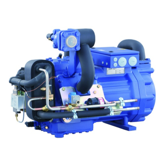
- Page 1 GEA Bock Compressor HGZ7 Assembly instructions HGZX7/1620-4 R404A/R507 HGZX7/1620-4 R410A HGZX7/1860-4 R404A/R507 HGZX7/1860-4 R410A HGZX7/2110-4 R404A/R507 HGZX7/2110-4 R410A HGZ7/1620-4 R22 HGZ7/1860-4 R22 HGZ7/2110-4 R22 engineering for a better world...
- Page 2 Observe the safety instructions contained in these instructions. These instructions must be passed onto the end customer along with the unit in which the compres- sor is installed. Manufacturer GEA Bock GmbH 72636 Frickenhausen Contact GEA Bock GmbH Benzstraße 7...
-
Page 3: Table Of Contents
Contents Page Safety 1.1 Identification of safety instructions 1.2 Qualifications required of personnel 1.3 General safety instructions 1.4 Intended use Product description 2.1 Short description standard design 2.2 ain and functional parts 2.3 Short description optional design 2.4 Name plate 2.5 Type key Areas of application 3.1 Refrigerants 3.2 Oil charge 3.3 Limits of application... -
Page 4: Safety
1| Safety 1.1 Identification of safety instructions: DANGER Indicates a dangerous situation which, if not avoided, will cause immediate fatal or serious injury. WARNING Indicates a dangerous situation which, if not avoided, may cause fatal or serious injury. CAUTION Indicates a dangerous situation which, if not avoided, may cause fairly severe or minor injury. -
Page 5: General Safety Instructions
The compressor may not be used in potentially explosive environments! These assembly instructions describe the standard version of the compressor named in the title manufactured by GEA Bock. GEA Bock refrigerating compressors are intended for installation in a machine (within the EU according to the EU Directives 2006/42/EC Machinery Directive, 97/23/EC Pressure Equipment Directive). -
Page 6: Product Description
2| Product description 2.1 Short description standard version Semi-hermetic, two-stage, six cylinder reciprocating compressor with suction-gascooled drive motor. Stages divided into LP / HP at the ratio of 2 : 1 Compressor with intermediate pressure shut-off mounted and insulated. Terminal box Intermediate pressure Notice chamber CE certification for piping (only for HGZ7/2110-4) Oil pump Name plate Charge plug Oil sight glasses Oil drain plug... - Page 7 2| Product description 2.2 Short description optional version, enclosed L iquid subcooler, expansion valve, solenoid valve, filter drier and a sight glass enclosed separately, for individual, external mounting (Fig. 3). Fig. 3 2.3 Short description optional version, mounted L iquid subcooler, expansion valve, solenoid valve, filter drier and a sight glass mounted directly to the compressor, piped and insulated (Fig. 4). Expansion valve Liquid subcooler Fig. 4 Sight glass Solenoid valve Filter drier Dimension and connection values can be found in Chapter 10...
-
Page 8: Type Key
2| Product description 2.4 Name plate (example) GEA Bock GmbH 72636 Frickenhausen, Germany Y/YY AN35455A040 Y/YY Fig. 5 Type designation Voltage, circuit, frequency Machine number Nominal rotation speed 50 Hz Type code Displacement Maximum operating current low pressure stage ND = Starting current (rotor blocked) -
Page 9: Areas Of Application
3| Areas of application 3.1 Refrigerants • HFKW : R404A/R507, R410A • (H)FCKW: 3.2 Oil charge The compressors are filled at the factory with the following oil type: - für R404A/R507, R410A FUCHS Reniso Triton SE 55 - für R22 FUCHS Reniso SP 46 Compressors with ester oil charge (FUCHS Reniso Triton SE 55) are marked with an X in the type designation (e.g. HGZX7/2110-4 R404A). INFO For refilling, we recommend the above oil types. Alternatives: see lubricants table, Chapter 8.5. ATTENTION The oil level must be in the max. - Page 10 3 | Areas of application R404A/R507 Fig. 7 R410A Fig. 8 Unlimited application range Evaporation temperature (°C) Condensing temperature (°C) ∆t suction gas superheat (K) Design for other areas on request Fig. 9 Max. permissible operating pressure (LP/MP/HP) : 19/19/28 bar 1) LP = low pressure MP = intermediate pressure HP = high pressure...
-
Page 11: Subcooling Temperature
3 | Areas of application 3.4 Subcooling temperature The design of the expansion valve on the compressor can be defined with the help of the diagram by approximately calculating the subcooling temperature arising in the relevant operating conditions (t Diagrams for determining the subcooling temperature at the output of the liquid subcooler. Fig. 10 Fig. 11 = Subcooling temperature at the subcooler outlet (FUA) = Evaporating temperature Fig. 12... -
Page 12: Description Of Functions
4| Description of functions The refrigerant suctioned out of the evaporator (20) is compressed by the 4 cylinders of the LP stage (2) to intermediate pressure MP. After that, the superheated refrigerant flows through the intermediate pressure chamber (3), where it is cooled by the liquid subcooler system to reduce the discharge end temperature. The refrigerant then flows through the intermediate pressure line (4) to the electric motor of the compressor for to cool the motor. After this, the refrigerant is suctioned in by the two HP cylinders (5) and compressed to the final pressure. - Page 13 4| Description of functions 4.1 Two-stage refrigeration cycle with liquid subcooler Line A Line B Scope of supply Fig. 13 Explanations Compressor 15 Refrigerant receiver Cylinder LP-stage 16 Filter drier Intermediate pressure chamber MP 17 Solenoid valve Intermediate pressure line MP 18 Sight glass Cylinder HP-stage 19 Expansion valve (evaporator) 6 Liquid subcooler 20 Evaporator...
-
Page 14: Compressor Assembly
5| Compressor assembly INFO New compressors are factory-filled with inert gas (3 bar nitrogen). Leave this service charge in the compressor for as long as possible and prevent the ingress of air. Check the compressor for transport damage before starting any work. 5.1 Storage and transportation Storage at (-30°C) - (+70°C), maximum permissible relative humidity 10% -95 %, no condensation. Do not store in a corrosive, dusty, vaporous atmosphere or in a com- bustible environment. - Page 15 The accompanying expansion valve is designed and adjusted for the compressor and the listed refrigerant (sensor charge, nozzle). Only use expansion valves approved and supplied by GEA Bock! INFO The intermediate pressure line and intermediate pressure chamber are fully insulated at the factory.
- Page 16 5| Compressor assembly Intermediate pressure chamber Intermediate pressure line (Shown without insulation) Fig. 20 Connection of pressure compensation line for expansion valve 16 " UNF Refrigerant injection connection M22 x 1,5 Schrader connection for intermedie-pressure gauge 16 " UNF Position of temperature sensor / unpainted...
- Page 17 5| Compressor assembly 5.4 Installation example, liquid subcooler with accessories Dia. 16 mm Dia. 16 mm Heat insulation Line A Line B Dia. 16 mm from the receiver Dia.12 mm to the evaporator Dia.12 mm Dia.12 mm Dia.6 mm Dia.16 mm Intermediate pressure chamber MP Line B Fig.21 1 Liquid subcooler...
- Page 18 5| Compressor assembly 5.5 Factory-installed liquid subcooler system (optional design) Liquid subcooler, expansion valve, solenoid valve and the sight glass are mounted directly at the compressor, piped and insulated. Fig.22 FUE: Liquid subcooler inlet FUA: Liquid subcooler outlet 5.6 Pipe connections ATTENTION Damage possible. Superheating can damage the valve. Remove the pipe supports therefore from the valve for soldering. Only solder using inert gas to inhibit oxidation products (scale) The pipe connections have graduated inside diameters so that pipes with standart millimetre and inch dimensions can be used.
-
Page 19: Pipes Dgb
5| Compressor assembly 5.7 Pipes Pipes and system components must be clean and dry inside and free of scale, swarf and layers of rust and phosphate. Only use air-tight parts. Lay pipes correctly. Suitable vibration compensators must be provided to prevent pipes being cracked and broken by severe vibrations. -
Page 20: Operating The Shut-Off Valves
5| Compressor assembly 5.9 Operating the shut-off valves Before opening or closing the shut-off valve, release the valve spindle seal by approx. ¼ of a turn counter-clockwise. After activating the shut-off valve, re-tighten the adjustable valve spindle seal clockwise. tighten release Valve spindle seal Fig. -
Page 21: Electrical Connection 21 E
6| Electrical connection Electrical connection DANGER Risk of electric shock! High voltage! Only carry out work when the electrical system is disconnected from the power supply! ATTENTION When attaching accessories with an electrical cable, a minimum bending radius of 3 x the cable diameter must be maintained for laying the cable. -
Page 22: Circuit Diagram For Part-Winding Start
6.2 Circuit diagram for part-winding start F1.2 F1.1 I=40% I=60% F1.1 F1.2 X SS X1 L1 L1 N N 43 43 11 /YYY X2 1 MP10 R2 R2 R2 Compressor terminal box Anschluákasten Verdichter Fig. 29 Main switch F1.1 Motor protection switch part winding 1 F1.2 Motor protection switch part winding 2 Fuse control current circuit... - Page 23 L1.1 L2.1 L3.1 L1.2 K2T K3T Y1 P> P< P™l Delay relay max. 1 s (slow release), part winding 2 D elay relay max. 20 s (slow release), Open solenoid Y1 (subcooler) D elay relay max. 20 s (slow release), compresssor switch-off (suction subcooler) Solenoid valve intermediate cooler Compressor motor Cold conductor (PTC sensor) Thermal protection thermostat (PTC sensor) Oil temperature (NTC sensor) PW MP10 BOCK COMPRESSORS...
-
Page 24: Standard Motor, Design For Direct Or Partial Winding Start
6| Electrical connection 6.3 Standard motor, design for direct or partial winding start Designation on the name plate Sticker on the terminal box Y/YY Y/YY Compressors with this marking are suitable for direct or partial winding start. The motor winding is subdivided into two parts: Part winding 1 = 50% and part winding 2 = 50%. -
Page 25: Electronic Trigger Unit Mp10
6| Electrical connection 6.4 Electronic trigger unit MP10 The compressor motor is fitted with cold conductor temperature sensors (PTC) connected to the electronic trigger unit MP 10 in the terminal box. Readiness to operate is signalled by the H3 LED (green) after the power supply is applied. In the case of excess temperature in the motor winding, the unit switches off the compressor and the H1 LED lights red. - Page 26 6| Electrical connection 6.6 Function test of the trigger unit MP10 Before start-up, troubleshooting or making changes to the control power circuit, check the functionality of the trigger unit: LED H1 LED H2 LED H3 Procedure green • Interrupt power supply (L1 or S1) •...
-
Page 27: Oil Sump Heater (Accessories)
6| Electrical connection 6.7 Oil sump heater (accessories) When the compressor is at a standstill, refrigerant diffuses into the lubricating oil of the compressors housing, depending on pressure and ambient temperature. This reduces the lubricating capacity of the oil. When the compressor starts up, the refrigerant contained in the oil evaporates out throught the reduction in pressure. The consequences can be foaming and migration of the oil, causing oil shocks under certain circumstances. -
Page 28: Commissioning
7| Commissioning 7.1 Preparations for start-up INFO In order to protect the compressor against inadmissible operating conditions, high pressure and low pressure pressostats are manda- tory on the installation side. The compressor has undergone trials in the factory and all functions have been tested. There are therefore no special running-in instructions. -
Page 29: Refrigerant Charge
7| Commissioning 7.5 Refrigerant charge CAUTION Wear personal protective clothing such as goggles and protective gloves! Make sure that the suction and pressure line shut-off valves are open. With the compressor switched off, add the liquid refrigerant directly to the condenser or receiver, breaking the vacuum. Pay attention to adequate refrigerant fill before starting up the compressor. During operation, refrigerant must be free of bubbles in sight glasses 1 and 2 of the liquid subcooler. If the refrigerant needs topping up after starting the compressor, it can be topped up in vapour form on the suction side, or, taking suitable precautions, also in liquid form at the inlet to the evaporator. - Page 30 7| Commissioning 7.7 Avoiding slugging ATTENTION Slugging can damage the compressor and cause refrigerant to leak. To prevent slugging: The complete refrigeration system must be properly designed. All components must be compatibly rated with each other with regard to output (particularly the evaporator and expansion valves).
-
Page 31: Maintenance
LP Valve plate kit 80194 high pressure side HP Piston-connecting 08995 08996 80112 rod kit Piston kit 80042 80048 80106 Connecting rod kit 80306 Oil pump kit 80116 Oil sump heater kit 08426 Only use genuine GEA Bock spare parts! -
Page 32: Replacing The Valve Plates
8| Maintenance 8.4 Replacing the valve plates The compressors are divided into an LP and an HP compressor stage. Different valve plate designs are required because of the different ducts in the individual compressor stages. WARNING The valve plates have been fitted with safety bolts to prevent any confusion. The safety bolts engage in the corresponding bores on the cylinder heads, the safety bolts must not be removed! Installation of the valve plates: Safety bolt Safety valve... -
Page 33: Extract From The Lubricants Table
Remove the compressor using an appropriate hoist. Dispose of the oil inside in accordance with the applicable national regulations. 8.7 Accessories Available accessories can be found on the Internet at www.gea.com. -
Page 34: Technical Data
9| Technical data Oil charge Weight ² No. of cylinders... -
Page 35: Dimensions And Connections
10| Dimensions and connections 10.1 Compressor in standard design Maße in mm Änderungen vorbehalten Massenschwerpunkt Dimensions in mm Subject to change without notice Centre of gravity Intermediate pressure mixed line mounted and insulated. (Liquid subcooler with accessories as an extra item) DV W Centre of gravity Rohrführung HGZ(X)7/1620+1860 Tube guidance HGZ(X)7/1620+1860 ÖV Maße in mm... - Page 36 10| Dimensions and connections 10.2 Compressor in optional design (Liquid subcooler with accessories attached directly to the compressor) ca.950 Rohrführung HGZ(X)7/1620+1860 Tube guidance HGZ(X)7/1620+1860 ü Layout of pipes a l t Änderungen vorbehalten Maße in mm v i t N FUA Dimensions in mm Subject to change without notice HGZ(X)7/1620+1860 i l , l i n...
- Page 37 10| Dimensions and connections Suction line see technical data, Chapter 9 Discharge line Liquid subcooler IN " Ø 16 mm - " Liquid subcooler OUT Ø 16 mm - Connection suction side, not lockable 8 “ NPTF Connection suction side, lockable 16 “ UNF Connection intermediate pressure, not lockable 8 “...
-
Page 38: Declaration Of Conformity And Installation
Applied harmonised standard: EN 60034-1:2010 EN 60204-1:2006 DECLARATION OF INSTALLATION for using the compressors within the European Union (in accordance with Machinery Directive 2006/42/EC) The manufacturer: GEA Bock GmbH, Benzstraße 7 72636 Frickenhausen, Tel.: 07022/9454-0 hereby declares that the refrigerating compressor HGZ7 complies with the basic requirements of Appendix II 1B of the Machinery Directive 2006/42/EC. Applied harmonised standard: EN 12693:2008 and the corresponding standards referenced A partly completed machine may only be put into operation when it has been established that the machine, into which the partly completed machine is to be installed, conforms to the r egulations of the Machinery Directive (2006/42/EC). - Page 39 11| Declaration of conformity PED - CLASSIFICATION (as per EU Pressure Equipment Directive 97/23/EC) DECLARATION OF CONFORMITY for use of the compressors within the European Union (as per EU Pressure Equipment Directive 97/23/EC) We hereby declare that piping of the refrigerant compressors HGZX7/2110-4 R404A, HGZX7/2110-4 R410A und HGZ7/2110-4 R22 agrees with the Pressure Equipment Directive 97/23/EG dated 29 May 1997. Valid for Category I piping Evaluation procedure module A The other parts of the piping fall under article 3§3 of the Guideline and correspond to good engineering practice Frickenhausen, 01.11.2011 ppa. Wolfgang Sandkötter,...
-
Page 40: Service
Dear customer, GEA Bock compressors are top-quality, reliable and service-friendly quality products. If you have any questions about installation, operation and accessories, please contact our technical service or specialist wholesaler and/or our representative. The GEA Bock service team can be contact- ed by phone with a toll-free hotline 00 800 / 800 000 88 or via e-mail: refrigeration@gea.com. Yours faithfully GEA Bock GmbH Benzstraße 7 72636 Frickenhausen... - Page 42 • • GEA Group is a global engineering company with multi-billion euro sales and operations in more than 50 countries. Founded in 1881, the company is one of the largest providers of innovative equipment and process technology. GEA Group is listed in the STOXX Europe 600 index.
Need help?
Do you have a question about the HGZ7 Series and is the answer not in the manual?
Questions and answers