Table of Contents
Advertisement
Quick Links
GEA Bock HG44e/HG56e
Assembly instructions
96416-03.2017-Gb
Translation of the original instructions
HG44e/475-4
HG44e/565-4
HG44e/665-4
HG44e/770-4
HG56e/850-4
HG56e/995-4
HG56e/1155-4
HG44e/475-4 S
HG44e/565-4 S
HG44e/665-4 S
HG44e/770-4 S
HG56e/850-4 S
HG56e/995-4 S
HG56e/1155-4 S
HGX44e/475-4
HGX44e/565-4
HGX44e/665-4
HGX44e/770-4
HGX56e/850-4
HGX56e/995-4
HGX56e/1155-4
HGX44e/475-4 S
HGX44e/565-4 S
HGX44e/665-4 S
HGX44e/770-4 S
HGX56e/850-4 S
HGX56e/995-4 S
HGX56e/1155-4 S
Advertisement
Table of Contents

Related Manuals for GEA HG44e/475-4


Summary of Contents for GEA HG44e/475-4
- Page 1 GEA Bock HG44e/HG56e Assembly instructions 96416-03.2017-Gb Translation of the original instructions HG44e/475-4 HG44e/475-4 S HGX44e/475-4 HGX44e/475-4 S HG44e/565-4 HG44e/565-4 S HGX44e/565-4 HGX44e/565-4 S HG44e/665-4 HG44e/665-4 S HGX44e/665-4 HGX44e/665-4 S HG44e/770-4 HG44e/770-4 S HGX44e/770-4 HGX44e/770-4 S HG56e/850-4 HG56e/850-4 S HGX56e/850-4 HGX56e/850-4 S...
-
Page 2: Table Of Contents
About these instructions Read these instructions before assembly and before using the compressor. This will avoid misunder- standings and prevent damage. Improper assembly and use of the compressor can result in serious or fatal injury. Observe the safety instructions contained in these instructions. These instructions must be passed onto the end customer along with the unit in which the compres- sor is installed. Manufacturer GEA Bock GmbH 72636 Frickenhausen Contact GEA Bock GmbH Benzstraße 7 72636 Frickenhausen Germany Phone +49 7022 9454 0 Fax +49 7022 9454 137 info@gea.com www.gea.com Contents Page Safety 1.1 Identification of safety instructions 1.2 Qualifications required of personnel 1.3 General safety instructions 1.4 Intended use Product description 2.1 Short description 2.2 Name plate 2.3 Type key... - Page 3 Contents Page Areas of application 3.1 Refrigerants 3.2 Oil charge 3.3 Limits of application Compressor assembly 4.1 Storage and transport 4.2 Setting up 4.3 Pipe connections 4.4 Pipes 4.5 Laying suction ans pressure lines 4.6 Operating the shut-off valves 4.7 Operating mode of the lockable service connections Electrical connection 5.1 Information for contactor and motor contactor selection 5.2 Standard motor, design for direct or partial winding start 5.3 Basic circuit diagram for partial winding start with standard motor 5.4 Special motor: design for direct or star-delta start 5.5 Basic circuit diagram for star-delta start with special motor 5.6 Electronic trigger unit INT69 G 5.7 Connecting of the trigger unit INT69 G 5.8 Functional test of the trigger unit INT69 G...
-
Page 4: Safety
1| Safety 1.1 Identification of safety instructions: DANGER Indicates a dangerous situation which, if not avoided, will cause immediate fatal or serious injury. WARNING Indicates a dangerous situation which, if not avoided, may cause fatal or serious injury. CAUTION Indicates a dangerous situation which, if not avoided, may cause fairly severe or minor injury. -
Page 5: General Safety Instructions
- Avoid contact with refrigerant necessarily. Contact with refrigerant can cause severe burns and skin damage. 1.4 Intended use WARNING The compressor may not be used in potentially explosive environments! These assembly instructions describe the standard version of the compressor named in the title man- ufactured by GEA. GEA refrigerating compressors are intended for installation in a machine (within the EU according to the EU Directives 2006/42/EC Machinery Directive, 2014/68/EU Pressure Equipment Directive). Commissioning is permissible only if the compressor has been installed in accordance with these as- sembly instructions and the entire system into which it is integrated has been inspected and approved in accordance with legal regulations. The compressors are intended for use in refrigeration systems in compliance with the limits of application. Only the refrigerant specified in these instructions may be used. -
Page 6: Product Description
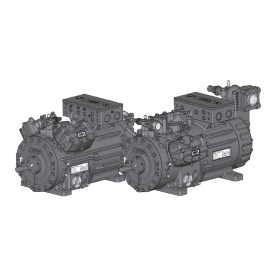
2 | Product description 2.1 Short description • HG44e: Semi-hermetic four-cylinder reciprocating compressor with suction-gas cooled drive motor. • HG56e: Semi-hermetic six-cylinder reciprocating compressor with suction-gas cooled drive motor. • Preferred application range: normal refrigerating and air-conditioning. Terminal box Transport eyelet Valve plate Cylinder cover Oil pump Name plate Oil sight glass Fig. 1 HG44e Discharge shut-off valve Suction shut-off valve Drive section Motor section HG56e Fig. 2 Dimension and connection values can be found in Chapter 10... -
Page 7: Type Key
2 | Product description 2.2 Name plate (example) GEA Bock GmbH 72636 Frickenhausen, Germany HGX44e/770-4 S AV12345A001 67,0 35,0 A 80,4 101 A 174 A SE 55 Fig. 3 Type designation Voltage, circuit, frequency 50 Hz Machine number Nominal rotation speed maximum operating current Displacement Starting current (rotor blocked) Voltage, circuit, frequency 60 Hz... -
Page 8: Areas Of Application
3 | Areas of application 3.1 Refrigerants • HFKW / HFC: R134a, R404A/R507, R407C, R407F • (H)FCKW / (H)CFC: 3.2 Oil charge The compressors are filled at the factory with the following oil type: - für R134a, R404A/R507, R407C, R407F FUCHS Reniso Triton SE 55 - für R22 FUCHS Reniso SP 46 Compressors with ester oil charge (FUCHS Reniso Triton SE 55) are marked with an X in the type designation (e.g. HGX44e/770-4). INFO For refilling, we recommend the above oil types. Alternatives: see lubricants table, Chapter 7.5 ATTENTION The oil level must be in the max. - Page 9 3 | Areas of application ATTENTION When operating in the vacuum range, there is a danger of air entering on the suction side. This can cause chemical reactions, a pressure rise in the condenser and an elevated compressed-gas temperature. Prevent the ingress of air at all costs! R134a Unlimited application range Supplementary cooling or...
- Page 10 3 | Areas of application R407C Fig. 8 R407F Fig. 9 Unlimited application range Supplementary cooling or reduced suction gas temperature Supplementary cooling and Maximum admissible reduced suction gas temperature operating pressure (g) Motor version S (LP/HP): 19/28 bar (more powerful motor) LP = Low pressure Evaporation temperature (°C) HP = High pressure Condensing temperature (°C) Design for other Suction gas superheat (K) areas on request Suction gas temperature (°C)
-
Page 11: Compressor Assembly
4 | Compressor assembly INFO New compressors are factory-filled with inert gas (3 bar nitrogen). Leave this service charge in the compressor for as long as possible and prevent the ingress of air. Check the compressor for transport damage before starting any work. 4.1 Storage and transport Storage at (-30°C) - (+70°C), maximum permissible relative humidity 10% - 95%, no condensation Do not store in a corrosive, dusty, vaporous atmosphere or in a com- bustible environment. -
Page 12: Pipe Connections
4 | Compressor assembly 4.3 Pipe connections ATTENTION Damage possible. Superheating can damage the valve. Remove the pipe supports from the valve for soldering. Only solder using inert gas to inhibit oxidation products (scale). The pipe connections have graduated inside diameters so that pipes with standart millimetre and inch dimensions can be used. T he connection diameters of the shut-off valves are rated for maximum compressor output. The actual required pipe cross section must be matched to the output. -
Page 13: Laying Suction Ans Pressure Lines
4 | Compressor assembly 4.5 Laying suction and pressure lines ATTENTION Improperly installed pipes can cause cracks and tears, the result being a loss of refrigerant. INFO Proper layout of the suction and discharge lines directly after the compressor is integral to the system’s smooth running and vibration behaviour. -
Page 14: Operating The Shut-Off Valves
4 | Compressor assembly 4.6 Operating the shut-off valves Before opening or closing the shut-off valve, release the valve spindle seal by approx. ¼ of a turn counter-clockwise. After activating the shut-off valve, re-tighten the adjustable valve spindle seal clockwise. Tighten Release Valve spindle seal Fig. 12 Fig. 13 4.7 Operating mode of the lockable service connections Connection cannot Service connection be shut off closed Pipe connection Connection Spindle blocked Fig. 14 Opening the shut-off valve: Compressor Spindle: turn to the left (counter-clockwise) as far as it will go. -
Page 15: Electrical Connection
5| Electrical connection Electrical connection DANGER Risk of electric shock! High voltage! Only carry out work when the electrical system is disconnected from the power supply! ATTENTION When attaching accessories with an electrical cable, a minimum bending radius of 3 x the cable diameter must be maintained for laying the cable. - Page 16 5.3 Basic circuit diagram for part winding start with standard motor FC1.2 FC1.1 I> I> I> I> I> I> FC1.1 FC1.2 L3 N PE Y/YY B1 B2 INT69 Compressor terminal box Anschlußkasten Verdichter Fig. 16 High pressure safety monitor Safety chain (high/low pressure monitoring ) Cold conductor (PTC sensor) motor winding Thermal protection thermostat (PTC sensor) Release switch (thermostat) Datum 20.02.2009 DELTA-P II Oil differential pressure sensor DELTA-P II (accessorie) Bearb.
- Page 17 L1.1 L2.1 L3.1 L1.2 P> 6.a.5 Θ Θ Θ DELTA- P II 6.1.8 FC1.1/1.2 Motor protection switch 6.2.8 Control power circuit fuse 6.5.8 INT69 G Electronic trigger unit INT69 G 6.a.8 Delay relay for contactor switchover Main switch PW INT69 HG44/56 Mains contactor (part winding 1) Mains contactor (part winding 2) BOCK COMPRESSORS Control voltage switch...
- Page 18 5| Electrical connection The motor is wired for direct start (YY) at the factory. For part winding start Y / YY, the bridges must be removed and the motor feed line connected according to the circuit diagram: 400 V Direktstart YY Teilwicklungsstart Y/YY Direct start YY Part winding start Y/YY ATTENTION Failure to do this results in opposed rotary fields and results in damage to the motor. After the motor starts up via partial winding 1, partial winding 2 must be switched on after a maximum delay of one second .
-
Page 19: Special Motor: Design For Direct Or Star-Delta Start
5| Electrical connection 5.4 Sondermotor: Ausführung für Direkt- oder Stern-Dreieck-Anlauf 5.4 Sondermotor: Ausführung für Direkt- oder Stern-Dreieck-Anlauf 5.4 Sondermotor: Ausführung für Direkt- oder Stern-Dreieck-Anlauf 5.4 Special motor: design for direct or star-delta start Für den Stern-Dreieck-Anlauf ist eine mechanische Anlaufentlastung mit Bypass-Magnetventil Für den Stern-Dreieck-Anlauf ist eine mechanische Anlaufentlastung mit Bypass-Magnetventil Für den Stern-Dreieck-Anlauf ist eine mechanische Anlaufentlastung mit Bypass-Magnetventil A mechanical unloaded start with bypass solenoid valve (accessories) is required for the... -
Page 20: Basic Circuit Diagram For Star-Delta Start With Special Motor
5.5 Basic circuit diagram for star-delta start with special motor FC1.1 I> I> I> FC1.1 FC1.2 FC1.2 I> I> I> L3 N PE ˜ B1 B2 INT69G Compressor terminal box Anschlußkasten Verdichter Fig. 17 High pressure safety monitor Safety chain (high/low pressure monitoring ) Cold conductor (PTC sensor) motor winding Thermal protection thermostat (PTC sensor) Release switch (thermostat) DELTA PII Oil differential pressure sensor DELTA-P II (accessorie) Datum 20.02.2009 Oil sump heater... - Page 21 L1.1 L2.1 L3.1 L1.2 P> 6.4.6 Θ Θ Θ DELTA- P II 2.1.5 2.1.8 2.1.8 2.1.7 Control power circuit fuse 2.2.8 2.2.8 2.2.5 INT69 G Electronic trigger unit INT69 G 2.2.7 Delay relay for contactor switchover 14 2.5 Main switch Mains contactor Δ-contactor D/S INT69 HG44/66 neu Y-contactor BOCK COMPRESSORS Control voltage switch...
-
Page 22: Electronic Trigger Unit Int69 G
5| Electrical connection 5.6 Electronic trigger unit INT69 G The compressor motor is fitted with cold conductor temperature sensors (PTC) connected to the electronic trigger unit INT69 G in the terminal box. In case of excess temperature in the motor winding, the INT69 G deactivates the motor contactor. Once cooled, it can be restarted only if the electronic lock of the output relay (terminals B1+B2) is released by interrupting the supply voltage. - Page 23 5| Electrical connection 5.8 Function test of the trigger unit INT69 G Before commissioning, after troubleshooting or making changes to the control power circuit, check the functionality of the trigger unit. Perform this check using a continuity tester or gauge. Relay position INT69 G Gauge state Relay position Deactivated state 11-12 INT69 G switch-on 11-14 B2 12 14 11 Remove PTC connector 11-12 Fig. 19 Insert PTC connector 11-12 Reset after mains on 11-14...
-
Page 24: Oil Sump Heater (Accessories)
5| Electrical connection 5.9 Oil sump heater (accessories ) When the compressor is at a standstill, refrigerant diffuses into the lubricating oil of the compressors housing, depending on pressure and ambient temperature. This reduces the lubricating capacity of the oil. When the compressor starts up, the refrigerant contained in the oil evaporates out throught the reduction in pressure. The consequences can be foaming and migration of the oil, causing oil shocks under certain circumstances. Operation: The oil sump heater operates when the compressor is at a standstill. When the compres- sor starts up, the oil sump heater switches off again automatically. Connection: The oil sump heater must be connected via an auxiliary contact (or parallel wired auxili- Anschlussschema für Ölsumpfheizung ary contact) of the compressor contactor to a seperate electric circuit. Connection diagramm for oil sump heater El. data: 230 V - 1 - 50/60 Hz, 160 W. Plan de raccordement pour résistance de carter d‘huile Fig. 20 ATTENTION Connection to the current path of the safety control chain is not permitted. -
Page 25: Preparations For Start-Up
6 | Commissioning 6.1 Preparations for start-up INFO To protect the compressor against inadmissible operating conditions, high pressure and low pressure pressostats are mandatory on the installation side. The compressor has undergone trials in the factory and all functions have been tested. There are therefore no special running-in instructions. Check the compressor for transport damage! 6.2 Pressure integrity test The compressor has been tested in the factory for pressure integrity. If however the entire system is to be subjected to a pressure integrity test, this should be carried out in accordance with EN 378-2 or a corresponding safety standard without the inclusion of the compressor. -
Page 26: Refrigerant Charge
6| Commissioning 6.5 Refrigerant charge CAUTION Wear personal protective clothing such as goggles and protective gloves! Make sure that the suction and pressure line shut-off valves are open. With the compressor switched off, add the liquid refrigerant directly to the condenser or receiver, breaking the vacuum. If the refrigerant needs topping up after starting the compressor, it can be topped up in vapour form on the suction side, or, taking suitable precautions, also in liquid form at the inlet to the evaporator. ATTENTION Avoid overfilling the system with refrigerant! To avoid shifts in concentration, zeotropic refrigerant blends must always only be filled into the refrigerating plant in liquid form. Do not pour liquid coolant through the suction line valve on the compressor. It is not permissible to mix additives with the oil and refrigerant. -
Page 27: Connection Of Oil Level Regulator
6| Commissioning 6.7 Avoiding slugging ATTENTION Slugging can damage the compressor and cause refrigerant to leak. To prevent slugging: The complete refrigeration system must be properly designed. All components must be compatibly rated with each other with regard to output (particularly the evaporator and expansion valves). Suction gas superheat at the compressor input should be min. 7 - 10 K. (check the setting of the expansion valve). The system must reach a state of equilibrium. Particularly in critical systems (e.g. several evaporator points), measures are recommended such as replacement of liquid traps, solenoid valve in the liquid line, etc. There should be no movement of coolant whatsoever while the compressor is at a standstill. 6.8 Connection of oil level regulator Oil level regulation systems have proven themselves with parallel circuits of several compressors. -
Page 28: Maintenance
Item No. Set of gaskets kit 81598 Valve plate kit 80965 80966 Oil pump kit 80950 Oil sump heater kit 81252 230 V ~ HG56e / ... 850-4 (S) 995-4 (S) 1155-4 (S) Designation Item No. Item No. Item No. Set of gaskets kit 81599 Valve plate kit 80965 80966 Oil pump kit 80950 Oil sump heater kit 81252 230 V ~ Only use genuine GEA spare parts! -
Page 29: Accessories
7 | Maintenance 7.4 Accessories Available accessories can be found on the Internet at www.gea.com 7.5 Extract from the lubricants table The oil type filled as standard in the factory is marked on the name plate. This oil type should be used as a preference. Alternatives are stated in the extract from our lubricants table below. Refrigerants GEA standard oil types Recommended alternatives Fuchs Reniso Triton SEZ 32 HFKW Esso/Mobil EAL Arctic 46 Fuchs Reniso Triton SE 55 (e.g. R134a, R407C) Sunoco Suniso SL 46 Texaco Capella HFC 55... -
Page 30: Accessories
8| Accessories 8.1 Capacity regulator ATTENTION If the capacity regulator is installed at the factory, it is subsequently installed and connected by the customer. CR 1 CR 1 CR 2 HG44e HG56e Fig. 22 Fig. 23 Fig. 24 Delivery condition 1 (from the factory): Before commissioning, the blind flange with Cylinder cover prepared for capacity regulator. screws must be removed and replaced by the new set capacity regulator with O-ring joints and screws. Observe position and construction of the capacity regulator. - Page 31 5 minutes per capacity-regulated operating hour. An assured oil return can also be realised by a 100% capacity requirement after each compressor restart. Electrical actuation of the solenoid valve: Normally open, (cor- responds to 100 % compressor capacity). Special accessories are only premounted in the factory if ordered specially by customer. Retrofitting is possible in full compliance with the safety instructions and repair instructions enclosed with the kits. Information about the use, operation, maintenance and servicing of the components is available in the printed literature or on the internet under www.gea.com. For the capacity regulator a step protection is optional available, Art-Nr. 81449. Fig. 26...
-
Page 32: Technical Data
9| Technical data Oil charge 380-420 V Y/YY - 3 - 50 Hz PW 440-480 V Y/YY - 3 - 60 Hz PW PW = Part Winding Winding ratio : 50% / 50% No. of cylinders... - Page 33 9| Technical data Oil charge 380-420 V Y/YY - 3 - 50 Hz PW 440-480 V Y/YY - 3 - 60 Hz PW PW = Part Winding Winding ratio : 50% / 50% No. of cylinders...
-
Page 34: Dimensions And Connections
Unbemaßte Radien / Undimensioned rad of the grant of a patent, utility model or design. Geprüft / Verified Zuder 18.05.16 GEA Bock GmbH - Benzstraße 7 - 72636 Frickenhausen - Germany - www.bock.de Freigabe / Approved Layh Layh Maß Dimension Passung / Clearance 18.05.16... - Page 35 Freigabe / Approved Layh Layh 3 x M6 payment of damages. All rights reserved in the event GEA Bock GmbH - Benzstraße 7 - 72636 Frickenhausen - Germany - www.bock.de 25.08.16 üft / Appr. Maß / Dimension Passung / Clearance GEA Bock G Zust.
-
Page 36: Declaration Of Installation
11 | Declaration of installation DECLARATION OF INSTALLATION for using the compressors within the European Union (in accordance with Machinery Directive 2006/42/EC) The manufacturer: GEA Bock GmbH, Benzstraße 7 72636 Frickenhausen, Tel.: 07022/9454-0 hereby declares that the refrigerating compressors HG44e and HG56e complies with the basic requirements of Appendix II 1B of the Machinery Directive 2006/42/EC. Applied harmonised standard: EN 12693:2008 and the corresponding standards referenced A partly completed machine may only be put into operation when it has been established that the machine, into which the partly completed machine is to be installed, conforms to the r egulations of the Machinery Directive (2006/42/EC). The manufacturer undertakes to transmit electronically the special documentation required by individual states for partly completed machinery on request. The special technical documentation required for partly completed machinery has been created in accordance with Appendix VII Part B. Person responsible for documentation is: Wolfgang Sandkötter, Benzstraße 7, 72636 Frickenhausen. Frickenhausen, 25.11.2013 ppa. Wolfgang Sandkötter, Chief Development Officer... -
Page 37: Service
12| Service Dear customer, GEA compressors are top-quality, reliable and service-friendly quality products. If you have any questions about installation, operation and accessories, please contact our technical service or specialist wholesaler and/or our representative. The GEA service team can be contacted by phone with a toll-free hotline 00 800 / 800 000 88 or via e-mail: info@gea.com Yours faithfully GEA Bock GmbH Benzstraße 7 72636 Frickenhausen Germany... - Page 38 • • GEA Group is a global engineering company with multi-billion euro sales and operations in more than 50 countries. Founded in 1881, the company is one of the largest providers of innovative equipment and process technology. GEA Group is listed in the STOXX ®...
Need help?
Do you have a question about the HG44e/475-4 and is the answer not in the manual?
Questions and answers