Table of Contents
Advertisement
Quick Links
NF695C6-3455 Series
User's Manual
NO. G03-NF695C6-F
Revision: 1.0
Release date: September 15, 2020
Trademark:
* Specifications and Information contained in this documentation are furnished for information use only, and are
subject to change at any time without notice, and should not be construed as a commitment by manufacturer.
Advertisement
Table of Contents

Subscribe to Our Youtube Channel
Related Manuals for JETWAY NF695C6-3455 Series


Summary of Contents for JETWAY NF695C6-3455 Series
- Page 1 NF695C6-3455 Series User’s Manual NO. G03-NF695C6-F Revision: 1.0 Release date: September 15, 2020 Trademark: * Specifications and Information contained in this documentation are furnished for information use only, and are subject to change at any time without notice, and should not be construed as a commitment by manufacturer.
- Page 2 Environmental Protection Announcement Do not dispose this electronic device into the trash while discarding. To minimize pollution and ensure environment protection of mother earth, please recycle.
-
Page 3: Table Of Contents
TABLE OF CONTENT ENVIRONMENTAL SAFETY INSTRUCTION ................iv USER’S NOTICE ........................v MANUAL REVISION INFORMATION ..................v ITEM CHECKLIST ........................v CHAPTER 1 INTRODUCTION OF THE MOTHERBOARD FEATURE OF MOTHERBOARD ................1 SPECIFICATION ......................2 LAYOUT DIAGRAM ....................3 CHAPTER 2 HARDWARE INSTALLATION JUMPER SETTING .....................8 CONNECTORS AND HEADERS ................13 2-2-1 CONNECTORS .....................13 2-2-2... -
Page 4: Environmental Safety Instruction
Environmental Safety Instruction Avoid the dusty, humidity and temperature extremes. Do not place the product in any area where it may become wet. 0 to 60 centigrade is the suitable temperature. (The figure comes from the request of the main chipset) ... -
Page 5: User's Notice
USER’S NOTICE COPYRIGHT OF THIS MANUAL BELONGS TO THE MANUFACTURER. NO PART OF THIS MANUAL, INCLUDING THE PRODUCTS AND SOFTWARE DESCRIBED IN IT MAY BE REPRODUCED, TRANSMITTED OR TRANSLATED INTO ANY LANGUAGE IN ANY FORM OR BY ANY MEANS WITHOUT WRITTEN PERMISSION OF THE MANUFACTURER. -
Page 6: Chapter 1 Introduction Of The Motherboard
Chapter 1 Introduction of the Motherboard 1-1 Feature of Motherboard Intel ® Apollo Lake series SoC Processor, with low power consumption never denies high performance 1 * SO-DIMM slot supports 1* 1867 MHz DDR3L SO-DIMM, up to 8GB ... -
Page 7: Specification
1-2 Specification Spec Description Design Mini-ITX form factor; PCB size: 17.0x17.0cm Intel ® Apollo Lake *SoC CPU *CPU model varies from different IPC options. Please consult your dealer for more information of onboard CPU. 1*DDR3L SO-DIMM slot Memory Support DDR3L 1867 MHz SO-DIMM up to 8GB ... -
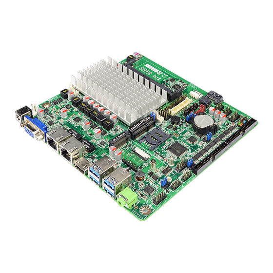
Page 8: Layout Diagram
1* PS2 Keyboard /Mouse header 1* Front panel audio header 1* 10-pin GPIO header 1*SMBUS header 1* front panel buzzer header 1* LVDS header (Selectable with EDP) 1*1* EDP header (Selectable with LVDS) 1* LVDS/EDP inverter header ... - Page 9 Motherboard Internal Diagram SYSFAN Internal 12V DC-in Connector DDR3L Slot LAN1_LED Header (SODIMM1) Full-size Mini-PCIE Slot (MPE1) LVDS *Rear IO M.2 Socket 3 Slot Connector (M2) (Refer to Page-3) SATA Power-out Connector LAN2_LED Header CPUFAN SMBUS Header SATAIII Port Inverter *SIMCARD Slot FP_BUZZ GPIO Port...
- Page 10 Jumper Positions: JMD1 ATX_AT JMD3 JMD2...
- Page 11 Jumper Jumper Name Description COM1 Serial Port Power Select 4-pin Block JMD1 JMD2 COM2 Serial Port Power Select 4-pin Block COM3 Serial Port Power Select 4-pin Block JMD3 MINIPCIE Power 3VSB / 3.3V Select 3-Pin Block ATX Mode / AT Mode Select 3-Pin Block ATX_AT LVDS/EDP Inverter Power 3.3V/5V/12V Select...
- Page 12 Headers Header Name Description Front Panel Header 9-pin Block (PWR LED/ HDD LED/ Power Button /Reset) F_USB1/ F_USB2/ USB 2.0 Header 9-pin Block F_USB3 COM1 RS232 Serial Port Header 9-pin Block COM2 RS232 Serial Port Header 9-pin Block COM3-6 RS232 Serial Port Combo Block 36-pin Block LAN1_LED LAN Activity LED Header...
-
Page 13: Chapter 2 Hardware Installation
Chapter 2 Hardware Installation 2-1 Jumper Setting (1) JMD1 (4-pin): COM1 Port Pin9 Function Select JMD1 COM1 Port Pin-9 → 2 4 6 2 4 6 JMD1 1 3 5 2-4 Closed: 4-6 Closed: 3-4 Closed: RING( Default); 12V. (2) JMD2 (4-pin): COM2 Header Pin9 Function Select JMD2 COM2 Header Pin-9 →... - Page 14 (3) JMD3 (4-pin): COM3 Header Pin9 Function Select JMD3 COM3 Header Pin-9 → 5 3 1 5 3 1 6 4 2 6 4 2 2-4 Closed: 3-4 Closed: 4-6 Closed: RING( Default); 12V. JMD3 (4) JP1 (3-pin): MINIPCIE SLOT POWER VCC3.3V / 3VSB Select →...
- Page 15 (5) ATX_AT (3-pin): AT/ATX Mode Select ATX_AT → ATX/AT Mode Select 1-2 Closed: ATX Mode (Default); ATX_AT 2-3 Closed: AT Mode. *ATX Mode Selected: Press power button to power on after power input ready; AT Mode Selected: Directly power on as power input ready. (6) JP4 (3-pin): LVDS / EDP Inverter Backlight VCC 5V/12V Select →...
- Page 16 (7) JP3 (4-pin): LVDS / EDP Panel VCC 3.3V/5V/12V Select → LVDS Panel VCC 2-4 Closed: 3-4 Closed: 4-6 Closed: VCC=3.3V VCC= 5V; VCC= 12V. (Default); (8) JP2 (8-pin): Jumper Combo Block Pin 1&2 of JP2 (8-pin): Case Open Message Display Function Select 1-2 Open: 1-2 Closed: Normal (Default);...
- Page 17 Pin 3&4 of JP2 (8-pin): TXE Override Setting 3-4 Open: 3-4 Closed: Normal (Default); TXE Override. Pin 5&6 of JP2 (8-pin):CLEAR CMOS 5-6 Open: 5-6 Closed: Normal (Default); Clear CMOS. Pin 7&8 of JP2 (8-pin): Clear ME_RTC 7-8 Open: 7-8 Closed: Normal (Default);...
-
Page 18: Connectors And Headers
2-2 Connectors and Headers 2-2-1 Connectors (1) Rear I/O Connectors *Refer to Page-3. Icon Name Function 12V DC–in system power connector Power Jack For user to connect compatible power adapter to provide power supply for the system. HDMI Port To connect display device that support HDMI specification. - Page 19 (2) DCIN2 (2-pin): Internal 12V DC-in power connector DCIN2 Pin1 Pin No. Definition +12V DC_IN Warning! The board has a 12V DC-in power connector (DCIN1) in I/O back panel and an internal 12V power connector (DCIN2). User can only connect one type of compatible power supply to one of them to power the system.
- Page 20 (4) SATAPW (4-pin) : SATA Power-out Connector Pin 1 SATAPW (5) CPUFAN (4-pin): CPU FAN Connector Pin1 +12V Fan Power Fan Speed Control CPUFAN (6) SYSFAN (4-pin): FAN Connector Pin1 +12V Fan Power SYSFAN Fan Speed Control...
-
Page 21: Headers
2-2-2 Headers *Notice: The following diagrams serves as illustration purpose only. Some of the headers are only optional. In the case of any differences please refer to the model you purchased for actual specifications. (1) FP (9-pin): Front Panel Header Pin 1 (2) F_USB1 / F_USB2 / F_USB3 (9-pin): USB 2.0 Port Header FP_USB1... - Page 22 (3) COM1/COM2 (9-pin): Serial Port Header : COM1 RS232/422/485 Serial Port Header : COM2 RS232 Serial Port Header. Pin 1 *COM1 COM2 Pin NO. RS232 *RS422 *RS485 Pin 1 DATA- Pin 2 DATA+ Pin 3 Pin 4 Pin 5 Pin 6 Pin 7 Pin 8 Pin 9...
- Page 23 (4) COM3-6 (36-Pin): RS232 Serial Port Header Pin:B1 Pin:B19 Pin:A1 Pin:A20 COM3-6 Pin NO. RS232 Pin NO. RS232 *COM3-6 Pin A1 DCD3 Pin B1 DSR3 COM3 Pin A2 SIN3 Pin B2 RTS3 Pin A3 SOUT3 Pin B3 CTS3 DTR3 Pin A4 Pin B4 Pin A5 Pin B5...
- Page 24 (5) LAN1_LED/LAN2_LED (2-pin): LAN Activity LED Header LAN1_LED LAN2_LED Pin1 (6) PS2KBMS (6-pin): PS/2 Keyboard & Mouse Header PS2KBMS Pin1 KB_DATA KB_CLK MS_CLK MS_DATA...
- Page 25 (7) FP_AUDIO (9-pin): Line-Out, MIC-In Header This header connects to Front Panel Line-out, MIC-In connector with cable. Pin 1 FP_AUDIO (8) GPIO (10-pin): GPIO Header GPIO Pin 1...
- Page 26 (9) SMBUS (5-pin): SMBUS Header SMBUS Pin1 DATA 3VSB FP_BUZZ (2-pin): Buzzer Header (10) Pin1 FP_BUZZ INVERTER (8-pin): LVDS Inverter Connector (11) Pin No. Definition Backlight Enable Pin 1 INVERTER Backlight PWM Back Light LED VCC Back Light LED VCC Backlight Up SW Backlight Down SW Warning! Find Pin-1 location of the inverter and make sure that the installation direction is correct!
- Page 27 *EDP (40-Pin): EDP wafer (12) Pin21 Pin1 Pin21 Pin40 Pin1 Pin20 Pin NO. Pin Define Pin NO. Pin Define Pin 1 Pin 21 Pin 2 Pin 22 Pin 3 EDP_TXN3 Pin 23 Pin 4 EDP_TXP3 Pin 24 Pin 5 Pin 25 Pin 6 EDP_TXN2 Pin 26...
- Page 28 *LVDS (30-Pin): 24-bit dual channel LVDS Header (13) LVDS Pin2 Pin 1 Pin NO. Pin Define Pin NO. Pin Define Pin 1 E-DATAN3 Pin 2 E-DATAP3 Pin 3 E-CLKN Pin 4 E-CLKP Pin 5 E-DATAN2 Pin 6 E-DATAP2 Pin 7 E-DATAN1 Pin 8 E-DATAP1...
-
Page 29: Chapter 3 Introducing Bios
Chapter 3 Introducing BIOS Notice! The BIOS options in this manual are for reference only. Different configurations may lead to difference in BIOS screen and BIOS screens in manuals are usually the first BIOS version when the board is released and may be different from your purchased motherboard. Users are welcome to download the latest BIOS version form our official website. -
Page 30: Bios Menu Screen
BIOS Boot Menu Screen (boot device options please refer to actual configuration) BIOS Menu Screen The following diagram show a general BIOS menu screen: Menu Bar General Help Items Current Setting Value Menu Items Function Keys... -
Page 31: Function Keys
Function Keys In the above BIOS Setup main menu of, you can see several options. We will explain these options step by step in the following pages of this chapter, but let us first see a short description of the function keys you may use here: ... -
Page 32: Main Menu
Main To change system basic configuration Advanced To change system advanced configuration Chipset To change chipset configuration Security Password settings Boot To change boot settings Save & Exit Save setting, loading and exit options. User can press the right or left arrow key on the keyboard to switch from menu bar. The selected one is highlighted. -
Page 33: Advanced Menu
System Date Set the date. Please use [Tab] to switch between date elements. System Time Set the time. Please use [Tab] to switch between time elements. 3-7 Advanced Menu OS Selection The optional settings: [Windows]; [Intel Linux]; [MSDOS]. *Note: User need to go to this item to select the OS mode before installing corresponding OS driver, otherwise problems will occur when installing the driver. - Page 34 The optional settings: [Disabled]; [Enabled]. ACPI Settings Press [Enter] to make settings for the following sub-items: ACPI Settings ACPI Sleep State Use this item to select the highest ACPI sleep state the system will enter when the suspend button is pressed. The optional settings are: [Suspend Disabled];...
- Page 35 Configuration/ Serial Port 5 Configuration/ Serial Port 6 Configuration Press [Enter] to make settings for the following items: Serial Port 2/3/4/5/6 Configuration Serial Port Use this item to enable or disable serial port (COM). The optional settings: [Disabled]; [Enabled]. When set as [Enabled], user can make further settings in the following items: Change Settings Use this item to select an optimal setting for Super IO Device.
- Page 36 WatchDog Reset Timer Use this item to enable or disable WDT reset function. The optional settings: [Disabled]; [Enabled]. When set as [Enabled], the following sub-items shall appear: WatchDog Reset Timer Value User can select a value in the range of [10] to [255] seconds when ‘WatchDog Reset Timer Unit’...
- Page 37 Console Redirection Settings The settings specify how the host computer and the remote computer (which the user is using) will exchange data. Both computers should have the same or compatible settings. Press [Enter] to make settings for the following items: Terminal Type The optional settings: [VT100];...
- Page 38 Hardware flow control uses two wires to send start/stop signals. The optional settings: [None]; [Hardware RTS/CTS]. VT-UTF8 Combo Key Support Use this item to enable VT-UTF8 Combination Key Support for ANSI/VT100 terminals. The optional settings: [Disabled]; [Enabled]. Recorder Mode With this mode enable only text will be sent. This is to capture Terminal data. The optional settings: [Disabled];...
- Page 39 sub-items shall appear: Console Redirection Settings The settings specify how the host computer and the remote computer (which the user is using) will exchange data. Both computers should have the same or compatible settings. Press [Enter] to make settings for the following items: Out-of-Band Mgmt Port The default setting is: [COM1].
- Page 40 *This item may or may not show up, depending on different configuration. PC Health Status ► Press [Enter] to view current hardware health status, make further settings in ‘SmartFAN Configuration’. ► SmartFAN Configuration Press [Enter] to make settings for SmartFan Configuration: SmartFAN Configuration CPUFAN Type/SYSFAN1 Type The optional settings: [4-Pin];...
- Page 41 The optional settings: [Enabled]; [Disabled]. EIST Use this item to enable or disable Intel SpeedStep. The optional settings: [Disabled]; [Enabled]. Turbo Mode Use this item to enable or disable Turbo Mode (requires Intel Speed Step Shift to be available and enabled.) The optional settings: [Disabled];...
- Page 42 option will not be created. The optional settings: [Disabled]; [Enabled]. Ipv6 PXE Support Use this item to enable Ipv6 PXE Boot Support. When set as [Disabled], Ipv6 boot option will not be created. The optional settings: [Disabled]; [Enabled]. PXE Boot Wait Time Use this item to set wait time to press [ESC] key to abort the PXE boot.
- Page 43 Press [Enter] to make settings for the following sub-items: Wake-up System with Fixed Time Use this item to enable or disable system wake on alarm event. The optional settings: [Disabled]; [Enabled]. When set as [Enabled], the following items shall appear: Wake-up Hour Use this item to select 0-23.
- Page 44 [Auto]: To disable legacy support if no USB devices are connected. XHCI Hand-off This is a workaround for OSes without XHCI hand-off support. The XHCI ownership change should be claimed by XHCI driver. The optional settings: [Enabled]; [Disabled]. USB Mass Storage Driver Support The optional settings: [Disabled];...
-
Page 45: Chipset Menu
3-8 Chipset Menu Uncore Configuration ► Press [Enter] to make settings for the following sub-items: GTT Size The optional settings: [2MB]; [4MB]; [8MB]. DVMT Pre-Allocated Use this item to select DVMT 5.0 Pre-Allocated (Fixed) Graphics Memory size used by the Internal Graphics Device. The optional settings: [64M];... - Page 46 The optional settings: [Disabled]; [LVDS]; [eDP]. * When set as [LVDS], user can make further setting in the following subitems: LCD Panel Type Use this item to select LCD panel used by Internal Graphics Device by selecting the appropriate setup item. The optional settings: [800x480 1ch 18-bit];...
- Page 47 South Cluster Configuration ► PCI Express Configuration Press [Enter] to make settings for the following sub-items: PCI Express Configuration Peer Memory Write Enable The optional settings: [Disabled]; [Enabled]. Compliance Mode The optional settings: [Disabled]; [Enabled]. Onboard PCIE LAN1 The optional settings: [Disabled]; [Enabled]. Onboard PCIE LAN2 The optional settings: [Disabled];...
-
Page 48: Security Menu
The optional settings: [Disabled]; [Enabled]. HD-Audio Support Use this item to enable or disable HD-Audio Support. The optional settings: [Disabled]; [Enabled]. System State after Power Failure Use this item to specify what state to go to when power re-applied after a power failure (G3 state). - Page 49 verify old password then to clear/change password. Press again to confirm the new administrator password. User Password If there is no password present on system, please press [Enter] to create new administrator password. If password is present on system, please press [Enter] to verify old password then to clear/change password.
-
Page 50: Boot Menu
(WFI_SIGNATURE_LIST data format) in root folder on a target file system device. Secure Boot Variable/Size/Key#/Key Source Platform Key (PK)/Key Exchange Keys/Authorized Signatures/Forbidden Signatures/ Authorized TimeStamps/OsRecovery Signatures Use this item to enroll Factory Defaults or load the keys from a file with: 1. -
Page 51: Save & Exit Menu
Setup Prompt Timeout Use this item to set number of seconds to wait for setup activation key. 65535(0xFFFF) means indefinite waiting. Bootup NumLock State Use this item to select the keyboard NumLock state. The optional settings: [On]; [Off]. Quiet Boot The optional settings: [Disabled];... - Page 52 Save Changes and Reset This item allows user to reset the system after saving the changes. Discard Changes and Reset This item allows user to reset the system without saving any changes. Restore Defaults Use this item to restore /load default values for all the setup options. Save as User Defaults Use this item to save the changes done so far as user defaults.
Need help?
Do you have a question about the NF695C6-3455 Series and is the answer not in the manual?
Questions and answers