
Related Manuals for Apec Water Ultimate Series


Summary of Contents for Apec Water Ultimate Series
- Page 1 ULTIMATE REVERSE OSMOSIS SYSTEM INSTALLATION INSTRUCTION & OWNER’S MANUAL Ver 4.0 Ver 4.0 www.FreeDrinkingWater.com www.FreeDr n gWater.com All Rights Reserved © APEC Water Systems All Rights Reserved © © APEC Water Systems...
- Page 3 Please keep this Owner’s Manual for future reference. Please keep this er’s Manual for future r erence. It contains useful information on how to maintain and care for your It contains useful information on how to maintain and care for your APEC Reverse Osmosis water filter system.
- Page 4 Thank you for choosing APEC reverse osmosis systems. Thank you for choosing C reverse osmosis system You now own the finest water filter in America. You now own the est water filter in Ame Please read and become familiar with instructions and parts needed before proceeding with the Please read and become familia with th i...
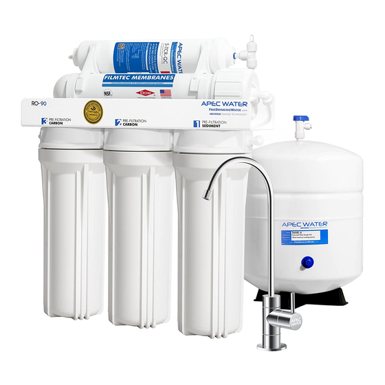
- Page 5 Components included with the RO system: ponents included with the R ystem: Make sure you have all these parts before starting installation. Make sure you have e parts before starting inst a tion. 1 RO system head 1 RO system head 3 Pre-filters in 3 Housings P e-fi fil ers in 3 Housings...
- Page 6 Component Itemization: ponent Itemization: Sediment pre-filter and housing (1 Sediment pre-filter and housing (1 -stage filter) -s -sta tag g e filter) Carbon block pre-filter and housing ( 2 Carbon block pre-filter and hous s in ing -stage filter) -stage filter) Carbon block pre-filter and housing ( 3 Carbon block pre-filter and i ng ( 3...
- Page 7 There are 2 types of fittings provided for connecting the system There are 2 types of fitti ovided for connecting the syst stem Fitting Types: ttin g Types: 1. Quick-Connect (QC) fitting: 1. Quick-Connect (QC) fitting: (no insert, sleeve, or nut s ert, sleeve, or nut Most of the fittings on the RO unit are this Most of the fittings on the RO unit are this...
- Page 8 THERE ARE TWO PARTS TO INSTALLING THE RO SYSTEM: T HE R E ARE TWO PARTS TO INSTA N G THE RO SYSTEM: Part I. Part I. Assemble the filters and housings onto the main system Assemble the filte e rs housings onto the main system Part II.
- Page 9 PART II. INSTALLING THE SYSTEM II. INSTALLING THE SYSTEM Space: Make sure there is sufficient space under the counter for installation (an area of about Space: Make sure there is suff ffic icie ient space under the counter for installatio n (a a rea of about 17”L x 6”W x 18”H for the system, 11”D x 18”H for tank).
- Page 10 Fig. 5A - Needle Valve Installation. 5 A - Needle Valve Installation. Attach the needle valve (C) to water supply adapter (A). Please apply 5-6 wraps of Attach the needle valve (C w at ater supply adapter (A). Please appl y 5- w raps of teflon tape to needle valve prior to connecting it to the water supply adapter (A).
- Page 11 3. Recommend Connection For Flex Line Riser: See Fig.6A. & Fig. 6D. Loosen nut and 3 Re Recommend Connection For Flex Li iser: See Fig.6A. & Fig. 6D. Lo osen separate cold water riser tube from faucet shank. Gently bend riser tube so that the Feed separate cold water riser tube fro rom fauc ucet shank.
- Page 12 Fig. 6C Fig. 6C Fig. 6D Fig. Fig. 6E g . 6E 4. Needle Valve: See Fig. 6C. Screw the Needle Valve onto the Adaptor tightly. Apply 6-8 rounds 4. Needle Valve: S Fig. 6C. Screw the Needle Valve onto the Adaptor tightly. Apply 6-8 rounds of Teflon tape onto Needle Valve before attaching it to the Adaptor.
- Page 13 Step 2: Drain Saddle Installation 2: Drain Saddle Installation Note: Note: To avoid annoying drainage noise, mount drain line as low as possible To avoid annoyin drai ainage noise, mount drain line possible on the vertical tailpiece, or on horizontal tailpiece. on the vertical ta il ilpi piec ece,...
- Page 14 3. See Fig.9, 9A. Make sure to align the drain saddle hole to the drilled hole perfectly. 3. See Fig. g.9, 9A. Make sure to align the dra in s d le hole to the drilled hole per fe fect ctly .
- Page 15 3. For Porcelain Sink: Porcelain enameled sinks can readily be chipped if care is not exercised F or or P orcelain Sink: Porcelain enameled si sink s ca can readily be chipped if care is not exer ercised when drilling the hole. Before starting the drill motor, apply firm downward pressure on the bit when drilling the hole.
- Page 16 Step 6: Connecting The System 6 : Connecting The System Summary of Tubing Connections: Summary of Tubing Connection ons: There are 4 connections: There are 4 connections: See Fig. 11 and 11A See Fig. 11 and 11A Point A to X: Point A to Connect RO to COLD water supply —...
- Page 17 Fig. 11A Fig. 11A Details on Tubing Connections: Details on Tubing Co Conn ections: To ensure a smooth and correct installation, please connect the water lines following the se- To ensure a smooth and correct installation, please connect the water lines following the se- quence and order outlined below.
- Page 18 3. Point W Waste water connection: o int W Waste water connection: Tubing color: T ubing color: Black tubing. Connect the BLACK tubing from the RO to the Drain Saddle. Black tubing. Connec t th e BL BLAC ACK tubing from the RO to the Drain addl Fitting type: Fitting type:...
- Page 19 7. Point Y o int Y Tank’s input & output connection: Tank’s input & output con nect ction: Prepare tank: See Fig.12. Apply 6-8 wraps of Teflon tape to tank’s threaded Output stem on top of P repare tank: See Fig.12. Apply 6- wrap aps of Teflon tape to tank’s threaded Outp p ut...
- Page 20 Using RO for Ice-maker only: RO for Ice-maker only: If you want the RO to feed your ice-maker (fridge) only, you should still connect the RO faucet you want the RO to feed your ic e-ma make ( fridge) only, you should still conne nect ct t...
- Page 21 (i (i.e. allow the system to rest at least a few hours a day). To properly maintain your APEC drinking water system, To properly maintain your APEC drinking water system, please use only genuine APEC Water replacement filters at please use only genuine APEC Water replacement filters at www.freedrinkingwater.com/filters www.freedrinkingwater.co...
- Page 22 2) Open housing: Have the RO standing upright. Slip the plastic wrench onto the #1 housing. O pen housing: Have the RO standing upri righ t. Slip the plastic wrench onto h ousing. Looking down from a top view, you should open the housing turning clockwise. If necessary, lay Looking down from a top view, shou l d open the housing turning...
- Page 23 5) Check for leaks! 5 Ch Check for leaks! 6) Drain the first tank of water (through faucet) to flush out the new membrane! The 2 Drain the first tank of water (thr hrou ough faucet) to flush out the new me e mb rane ! The 2...
- Page 25 OWNER’S MANUAL Please read this section for useful RO system and Please read this section for useful RO system and maintenance information. maintenance information. TABLE OF CONTENT TABLE OF CON Part I: Part RO Basics RO Basics Basic terms ................. Basic terms .......
- Page 26 Part I: RO BASICS Part RO BASICS This section provides basic concepts on how an RO system works, how it performs in relation to your This section provides basic concep w an RO system works, how it perfo o rm relation to your house’s water condition.
- Page 27 3) Water Pressure – The Most Important Factor! 3 Wa Water Pressure – The Most Important Fact ctor! RO systems run on water pressure. Therefore your water pressure has the most direct effect on how RO systems run on water pressure .
- Page 28 6) How Full Can My Tank Fill Up? 6 Ho How Full Can My Tank Fill Up? Your incoming water pressure determine how full and how fast the storage tank will be filled up. Y our incoming water pressure eter ermi mine h ow full and how fast the storage...
- Page 29 delivery pressure: delivery pressure: 14-gallon tank’s 1 -ga a llon tank’s 10 gallons —> 50 psi output pressure ( pressure inside tank ) gallons —> 50 psi output pressu re ( s sure inside tank ) 9.0 gallon —> 40 psi 9.0 gallon —>...
- Page 30 11) How to Test Your Water Pressure: H ow to Test Your Water Pressure: Get a water pressure gauge that adapts onto your sink or garden faucet (from hardware store), G et a water pressure gauge that adap apts nto your sink or garden faucet (from ardw dware store), attach gauge onto faucet, turn water on to FULL, then take a reading.
- Page 31 Part II: Trouble-Shoot Guide Part II: T u ble-Shoot Guide For Newly Installed RO System Installed RO System After installation, if you encounter any of the problems described below, please follow this guide to After installation, if you encounter the problems described below, please follow this guide to troubleshoot.
- Page 32 1) RO Makes Humming Noise 1 RO RO Makes Humming Noise When RO makes a humming noise, most likely it’s caused by air bubbles being trapped in the When RO makes a humming ise, ost likely it’s caused by air bubbles bei ng trapped in the “Check Valve”...
- Page 33 Output line is crimped —> Remove crimp O utput line is crimped —> Remove cr im imp Incorrect installation —> See Fig.11 & 11A. Verify all line connections. Incorrect installation —> See Fig. g.11 & 11A. Verify all line connections. Tank defective, no pre-charge pressure —>...
- Page 34 3) Sluggish Flow At Dispensing Faucet 3 Sl Slu u ggish Flow At Dispensing Fauc Insufficient water pressure (see “ Insufficient water pressure (see e “ “ ” for explanation) —> Check water pressure. If too ” for explanation) —> Check ater ressure.
- Page 35 6) System Does Not Shut-Off: Waste water runs all day - and Never Stops 6 Sy System Does Not Shut-Off: Waste a ter runs all day - and Never Stop Input pressure way too low (below 30psi). Not enough pressure to shut off the RO at all —> Input pressure way too low (be w 30 psi).
- Page 36 Test#2: Test Check Valve and ASO valve: #2: Test Check Valve and ASO valv Make sure there is some water in the tank (tank not empty). Make sure there is some t he tank (tank not empty). Remove the Black drain line from the drain saddle (so you can check waste flow drainage). Remove the Black drain line from the drain saddle (so you can check waste flow drainage).
- Page 37 Dispense some water from the RO faucet, this water comes directly from Dispense some w ater er from the RO faucet, this water come directly from Test #1 TDS from tank: # 1 TDS from tank: the tank. Test TDS, record the reading, then Do Test #2. the tank.
- Page 38 10) There is a leak at the Tank ball valve connection T here is a leak at the Tank ball v al alve connection If you are experiencing a leak from where the tank ball valve attaches to the tank stem, you may If you are experiencing a leak f ro m wh...
- Page 39 OTHER INFORMATION OTHER FORMATION AirGap Faucet Installation AirG ap Faucet Installation There are 3 colored tubings on your Air-Gap faucet. At the end of each 1/4” tubing there is a There are 3 colored tubings on your Ai Air-Gap faucet. At the end of each 1/4” tubing there is a “Quick Connect”...
- Page 40 How wastewater is disposed via Air-Gap faucet: w astewater is disposed via Air-Gap aucet: Waste water is routed through the Air-Gap faucet prior to being drained off into the standard drain- W aste water is routed through the Ai Air- r-Ga f aucet prior to being drained off in n to...
- Page 41 LIMITED PRODUCT WARRANTY LIMITED PRO D UCT WARRAN Scope S cope APEC takes pride in selling a superb line of products, including this reverse osmosis system (“Product”). As such, APEC expressly APEC takes pride in selling a superb line of pro cts, including this reverse osmosis system (“Product”).
- Page 42 CONDITIONS THAT RENDER THIS LIMITED PRODUCT WARRANTY VOID I TIONS THAT RENDER THIS LIMITED PROD ODUC UCT WARRANTY VOID THIS LIMITED PRODUCT WARRANTY SHALL BE VOID IF: I S LIMITED PRODUCT WARRANTY SHALL BE V OI 1. The Product is not operated in compliance with normal municipal water conditions for which the particular model of this Product 1.
- Page 44 Advanced Purification Engineering Corp. Advan Purification Engineering Corp 1320 S Johnson Drive 1320 S Johnson Drive City of Industry, CA 91745 City of Industry, CA 91745 For questions or comments please visit our website at: For questions or c om ments please visit our webs www.FreeDrinkingWater.com F reeDrinkingWater.co...
Need help?
Do you have a question about the Ultimate Series and is the answer not in the manual?
Questions and answers