
Related Manuals for Apec Water ULTIMATE RO-90


Summary of Contents for Apec Water ULTIMATE RO-90
- Page 1 ULTIMATE REVERSE OSMOSIS SYSTEM INSTALLATION INSTRUCTION & OWNER’S MANUAL Ver 6.2 www.FreeDrinkingWater.com All Rights Reserved © APEC Water Systems...
-
Page 3: Table Of Contents
Please keep this Owner’s Manual for future reference. It contains useful information on how to maintain and care for your APEC Reverse Osmosis water filter system. TABLE OF CONTENT Installation: Preparation ................. page 1 Filter housings assembly ............... page 4 Feed water connection .............. - Page 4 Thank you for choosing APEC reverse osmosis systems. You now own the finest water filter in America. Please read and become familiar with instructions and parts needed before proceeding with the in- stallation. BEFORE INSTALLATION: Inspect the system: Please take the system and all the components out of the box. Inspect the system and all the connection fittings carefully, make sure nothing is damaged during shipping.
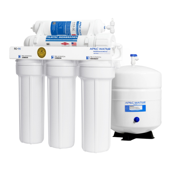
- Page 5 Components included with the RO system: Make sure you have all these parts before starting installation. 1 RO system head 3 Pre-filters in 3 Housings 1 Storage tank with pre installed membrane Installation kit includes: 1 Feed water adapter 1 Drain saddle 1 Faucet with tubing, 3/8”- 1/2”...
- Page 6 Component Itemization: Sediment pre-filter and housing (1 -stage filter) Carbon block pre-filter and housing ( 2 -stage filter) Carbon block pre-filter and housing ( 3 -stage filter) Membrane and housing (4 -stage filter) In-line carbon filter (5 -stage filter) Storage tank Tank ball valve ASO –...
- Page 7 THERE ARE TWO PARTS TO INSTALLING THE RO SYSTEM: Part I. Assemble the filters and housings onto the main system Part II. Installing the system Note: The RO Membrane Element has already been pre-installed. PART I. ASSEMBLE THE FILTERS AND HOUSINGS ONTO THE MAIN SYSTEM Remove plastic/paper wrappings on the 3 filters, put them into the 3 housings, and assemble the housings onto the main system as follow: 1.
-
Page 8: Feed Water Connection
PART II. INSTALLING THE SYSTEM Space: Make sure there is sufficient space under the counter for installation (an area of about 17”L x 6”W x 18”H for the system, 11”D x 18”H for tank). The RO system is best installed under the kitchen sink. But if that is not feasible you can install the system anywhere where there is a cold water supply with sufficient water pressure for the chosen RO model, and an outlet to drain off the drain water from the system. - Page 9 Fig. 4A - Needle Valve Installation. Attach the needle valve (C) to water supply adapter (A). Please apply 4-5 wraps of teflon tape to needle valve prior to connecting it to the water supply adapter (A). Fig. 4B - If your pipe has a 1/2” Connection. By attaching the 1/2”...
- Page 10 3. Recommend Connection For Flex Line Riser: See Fig. 5A. & Fig. 5E Loosen nut and separate cold water riser tube from shut off valve. Gently bend riser tube so that the Feed Water Adapter (Fig. 4) fits onto the shut off valve. Connect the riser tube, feed water adapter, and shut off valve together and tighten.
- Page 11 Insert Sleeve Compression Nut Push the tubing all the way into the needle valve while tightening compression nut. Apply Teflon Tape Here Fig. 5C Fig. 5D 4. Needle Valve: See Fig. 5D. Screw the Needle Valve onto the Adapter tightly. Apply 6-8 rounds of Teflon tape onto Needle Valve before attaching it to the Adapter.
- Page 12 Test for leaks after the system is completely installed: Close the Needle Valve (turn needle handle clock- wise all the way in to close). Turn ON the cold water supply to the sink faucet. If the Needle Valve or the Adapter leaks, check the connection and try applying more Teflon tape or tighten the brass nut some more to stop the leak.
- Page 13 3. See Fig. 8, 8A. Make sure to align the drain saddle hole to the drilled hole perfectly. Mis-aligning these two holes will block the drain water and cause membrane damage. Attach the drain saddle to the drain pipe and tighten the two screws evenly. 4.
- Page 14 3. For Porcelain Sink: Porcelain enameled sinks can readily be chipped if care is not exercised when drilling the hole. Before starting the drill motor, apply firm downward pressure on the bit until a crunching occurs. This will help keep the drill bit from walking when starting the hole. A small pilot hole will also aid the drill bit.
- Page 15 Faucet stem Sleeve & Tube insert Compression nut Counter Top Faucet Base Fig.9D Counter Top Opening Tube insert Black Locating Washer Lock Washer Lock Nut Sleeve Insert Sleeve Compression nut Compression Nut Tubing Fig. 9B Fig.9C Step 5: Positioning The System 1.
-
Page 16: Connecting The System
Step 6: Connecting The System IMPORTANT INSTALLATION NOTICE! The Quick connect fittings come with an end plug that needs to be removed be- fore the tubing can be connected. Please disconnect the end plugs at Points G and H from the Quick connect fittings before con- necting tubing. - Page 17 To Disconnect the Tubing: See Fig.10B. Push in and hold down on the collet ring square against the fitting. With the collet held in this position the tube can be removed. See Fig.10E. Summary of Tubing Connections: Fig.10E There are 4 connections: See Fig. 11 & Fig. 11A. Point A to X: Connect RO to COLD water supply —...
- Page 18 Fig. 11A Details on Tubing Connections: To ensure a smooth and correct installation, please connect the water lines following the sequence and order outlined below. Refer to Fig.11 & 11A for proper point locations. 1. Point Z - Faucet connection: Tubing color: Clear tubing.
- Page 19 3. Point W - Drain water connection: Tubing color: Black tubing. Connect the BLACK tubing from the RO to the Drain Saddle. Fitting type: Simply push the Clear tubing into the Quick Connect fitting. No Inserts, Sleeves or Nuts are needed to secure the connection. No Teflon tape needed here. 4.
- Page 20 Option: Ice-maker Connection If you want to connect product water from the RO to your ice-maker, you will need: • One T-fitting, preferably the quick-connect type fitting • Extra 1/4" tubing long enough to go from the RO system to your ice-maker •...
- Page 21 Step 7: System Start-Up 1. Turn on feed water: Slowly, turn on your Cold water supply. Open the Needle Valve (turn counter- clockwise) to allow the raw water to enter the system. Check for leaks! 2. Open tank valve: Open the tank’s ball valve to allow water to enter the tank. The tank’s valve is “On”...
-
Page 22: Maintenance
Keep the system indoors away from extreme heat or cold temperatures, and run the system within its reasonable output capacity (i.e. allow the system to rest at least a few hours a day). To properly maintain your APEC drinking water system, please use only genuine APEC Water replacement filters at www.freedrinkingwater.com/filters Stages 1, 2, 3 Pre-Filters: Replace every 12 months. - Page 23 Discard 3 used filters, wash housings with mild soap, rinse off. Put 3 new filters into their respective housings: sediment filter in stage-1, carbon block filters in stages 2 & 3. Close up the housings. Make sure each housing has a black O-ring in the threaded groves. First hand tighten the housing, then use filter wrench to fully tighten each housing.
- Page 24 5) Close the housing cap. Reconnect the WHITE tubing to the cap. Turn on the cold water supply and tank valve. Let the RO system run to re-fill the tank (takes about 2-3 hours). 6) Check for leaks! 7) Drain the first tank of water (through faucet) to flush out the new membrane! The 2 tank of water is ready for use.
-
Page 26: System Flow Diagram
OWNER’S MANUAL Please read this section for useful RO system and mainte- nance information. TABLE OF CONTENT Part I: RO Basics Basic terms ................. page 24 System flow diagram ..............page 24 Water pressure -- The most important factor ....... page 25 Tank -- Fill up time. -
Page 27: Part I: Ro Basics
Part I: RO BASICS This section provides basic concepts on how an RO system works, how it performs in relation to your house’s water condition. We hope this information helps keep your ROES system running at top performance for years to come. 1) Basic Terms GPD = Gallons Per Day (flow rate) PSI = Pounds per Square Inch (pressure) -
Page 28: Water Pressure - The Most Important Factor
3) Water Pressure – The Most Important Factor! RO systems run on water pressure. Therefore your water pressure has the most direct effect on how well your RO will perform. With sufficient water pressure (85 psi max.), your RO system will func- tion well, give high output with high removal rate, and fill up the storage tank quickly. -
Page 29: Icemaker And Multiple Output Points
6) How Full Can My Tank Fill Up? Your water pressure and temperature will determine how full and how fast the storage tank will be filled up. The stronger your input water pressure, the faster and fuller the tank can fill. If water pressure is low, the tank will fill slower and will not fill up to its full capacity. -
Page 30: Insufficient Water Pressure -- Problems With Non-Pump Systems
10) Insufficient Water Pressure – Problems with Non-Pump RO Systems: The 3 most common problems caused by low input water pressure: 1) Tank does not fill up, get little water from tank 2) Sluggish flow at the dispensing faucet 3) RO makes water slower than the claimed GPD If you experience these problems, This will often Please check your input water pressure as the first step. -
Page 31: Head Diagram
Part II: Trouble-Shoot Guide For Newly Installed RO System After installation, if you encounter any of the problems described below, please follow this guide to trouble- shoot. In most cases, the problem is quickly solved by following this guide. Non-Pumped RO HEAD DIAGRAM Fig. -
Page 32: No Water At Dispensing Faucet
1) Air Bubbles: Lots of Air bubbles in cup or bottle when filling It is quite normal to see air bubbles in a cup of pure water. This mainly occurs when a RO unit is first installed or when filters are being replaced. When new filters are installed to the unit, the filter housings are dry. -
Page 33: Filter Housing Is Leaking
3) Sluggish Flow At Dispensing Faucet Insufficient water pressure (see “ ” for explanation) —> Check water pressure. If too low for this RO Basics chosen RO model, either increase your water pressure or add pump to RO system. Input water to RO is blocked —> Make sure Feed water valve is fully opened and unhindered. Tank not filled yet —>... -
Page 34: Tds (Total Dissolved Solids) Level Reads Higher Than Normal
Step 3. Re-attach the filter housing to the RO head. Hand tighten the housing, then use the filter housing wrench and simply give an additional quarter inch turn. Do Not over tighten the housing. Step 4. Open the tank ball valve and feed water line. Check for leaks. If the filter housing continues to leak, please contact APEC technician for replacement assistance. -
Page 35: There Is A Leak At The Tank Ball Valve Connection
7) There is a leak at the Tank ball valve connection If you are experiencing a leak from where the tank ball valve attaches to the tank stem, you may not have applied enough Teflon tape to the stem when you first installed the valve. To correct this issue, please turn off the supply water to the system and turn on the drinking water faucet to completely empty the tank. -
Page 36: How To Test Ro's Shut-Off Function
10) How to Test RO’s Shut-Off Function: The RO system should shut off automatically when the tank is filled. When the RO fails to shut off after tank is filled, drain water will keep running down the drain depleting the pre-filters, the membrane, and may lead to higher water bills. -
Page 37: Makes Humming Noise
12) RO Makes Humming Noise When RO makes a humming noise, most likely it’s caused by air bubbles being trapped in the “Check Valve” during installation. See check valve on Fig. 17, point E (Page 29). To purge air from the check valve, do as follows: Step 1: Close the tank’s valve. -
Page 39: Other Information
OTHER INFORMATION AirGap Faucet Installation (Optional) There are 3 colored tubings on your Air-Gap faucet. At the end of each 1/4” tubing there is a “Quick Connect” fitting. The Quick Connect fittings is used to connect the Pure and Drain water line from the RO unit to the Air Gap Faucet. - Page 40 How drain water is disposed via Air-Gap faucet: Drain water is routed through the Air-Gap faucet prior to being drained off into the standard drain- pipe outlet. The 1/4” BLACK drain water line from the RO system will discharge through the 1/4” RED line to the Air-Gap faucet.
-
Page 41: Warranty
LIMITED PRODUCT WARRANTY Scope APEC takes pride in selling a superb line of products, including this reverse osmosis system (“Product”). As such, APEC expressly warrants to the original purchaser that, for a period of one (1) year from the date of purchase, the Product will be reasonably free of defects in materials and workmanship. - Page 42 CONDITIONS THAT RENDER THIS LIMITED PRODUCT WARRANTY VOID THIS LIMITED PRODUCT WARRANTY SHALL BE VOID IF: 1. The Product is not operated in compliance with normal municipal water conditions for which the particular model of this Product is intended. 2. The person seeking to invoke the warranty is not the original purchaser. That is, this Limited Product Warranty only extends to original purchasers.
- Page 44 Advanced Purification Engineering Corp. 1320 S Johnson Drive City of Industry, CA 91745 For questions or comments please visit our website at: www.FreeDrinkingWater.com For technical support contact us at: Techsupport@freedrinkingwater.com 1-800-880-4808...
Need help?
Do you have a question about the ULTIMATE RO-90 and is the answer not in the manual?
Questions and answers
New O ring installed but sediment filter housing leaking from threaded area