Table of Contents
Advertisement
Quick Links
ULTIMATE
INSTALLATION INSTRUCTION
& OWNER'S MANUAL
www.FreeD
www.FreeDrinkingWater.com
All Rights Reserv
All Rights Reserved © APEC Water Systems
REVERSE OSMOSIS SYSTEM
Models: RO-QUICK90
Mode
e
l
l
s
s :
:
D
D
D
r
r
r
in
n
k
k
k
k
ingWater.com
r r
v
ed
ed
ed
ed
©
©
©
©
APE
APE
APE
APEC
Water Systems
R
R
O -QUICK90
O
Ver 1.0
Ver 1.0
Advertisement
Table of Contents

Related Manuals for Apec Water Ultimate RO-QUICK90


Summary of Contents for Apec Water Ultimate RO-QUICK90
- Page 1 ULTIMATE REVERSE OSMOSIS SYSTEM INSTALLATION INSTRUCTION & OWNER’S MANUAL Ver 1.0 Ver 1.0 Models: RO-QUICK90 Mode O -QUICK90 www.FreeDrinkingWater.com www.FreeD ingWater.com All Rights Reserved © APEC Water Systems All Rights Reserv © © © © APEC Water Systems...
-
Page 3: Table Of Contents
Please keep this Owner’s Manual for future reference. Please keep this O r’s Manual for future e rence. It contains useful information on how to maintain and care for your It contains useful information on how to maintain and care for your APEC Reverse Osmosis water filter system. -
Page 4: Installation: In Installation: Preparation Preparation
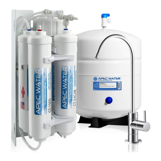
Thank you for choosing APEC reverse osmosis systems. h ank you for choosing A reverse osmosis system You now own the finest water filter in America. You now own the f e st t water filter in America. Please read and become familiar with instructions and parts needed before proceeding with the Pl Plea se read and become familiar with... - Page 5 Components included with the RO system: n ents included with the RO t em: Make sure you have all these parts before starting installation. a ke sure you have all parts before starting in a tion. 1 RO system head 1 RO system head 1 Storage tank 1 Storage tank...
- Page 6 Component Itemization: ent Itemization: Sediment pre-filter (1 Sediment pre-filter (1 -stage filter) -stage fil ilte Carbon pre-filter ( 2 Carbon pre-filter ( 2 -stage filter) -sta tage ge f ilter) Membrane and housing (3 Membrane and hou ousi sing ng (3 -stage filter) -stage filter) Carbon post-filter (4...
-
Page 7: Feed Water Connection
INSTALLING THE SYSTEM INST STAL ALLI N G THE SYSTEM Space: Make sure there is sufficient space under the counter for installation (an area of about Space: Make sure there is sufficient s s pa pace under the counter for installat n (a (an area of about 14”L x 6”W x 6.5”H for the system, 11”D x 18”H for tank). - Page 8 Fig. 2 - Needle Valve Installation. Fig. N eedle Valve Installation. Attach the needle valve (C) to water supply adapter (A). Please apply 5-6 wraps of Attach the needle valve (C) to w at ater upply adapter (A). Please appl 5- 5-6 wr wraps of teflon tape to needle valve prior to connecting it to the water supply adapter (A).
- Page 9 3. Recommend Connection For Flex Line Riser: See Fig. 5A. & Fig. 5E Loosen nut and separate cold 3. Recomm C onnection For Flex Line Riser: S g . 5A. & Fig. 5E Loosen nut and sepa para rate cold water riser tube from shut off valve.
- Page 10 Insert Insert Sleeve Slee e ve Compression Nut Compre pressi ssio o n Nut Push the tubing all the way into the needle valve Push the tubing all th h e way into the nee dle valve while tightening compression nut. while tightening com m pression nut.
-
Page 11: Drain Saddle Connection Drain Saddle Connection
Test for leaks after the system is completely installed: Close the Needle Valve (turn needle handle clock- Test for l ea eaks fter the system is completely instal le led: C lo lose the Needle Valve (turn need h an andl e clock- wise all the way in to close). - Page 12 3. See Fig. 8, 8A. Make sure to align the drain saddle hole to the drilled hole perfectly. 3. See Fig. 8, 8, 8 A . Make sure to align the drain addl dle hole to the drilled hole per fect ctly Mis-aligning these two holes will block the drain water and cause membrane damage.
-
Page 13: Faucet Mounting
3. For Porcelain Sink: Porcelain enameled sinks can readily be chipped if care is not exercised when 3. For Porce cela lain Sink: Porcelain enameled sinks ca read adily be chipped if care is not exer cise drilling the hole. Before starting the drill motor, apply firm downward pressure on the bit until a drilling hole. - Page 14 Faucet stem Faucet stem Sleeve Sleeve & & Tube insert Tube insert Compression nut Compression nut Counter Top Counter Top Faucet Base Faucet Fig.9D Fig.9D Counter Top Counte Opening Openin ning Tube insert Tube insert Black Locating Washer Black Loca a ting Washer Lock Washer Lock Washer Lock Nut...
-
Page 15: Connecting The Sys Yste Connecting The System
Step 6: Connecting The System Step 6: Co Conn e cting The System IMPORTANT INSTALLATION NOTICE! T ANT INSTALLATION N ICE! The Quick connect fittings come with an Th The Q uick connect fittings come with end plug that needs to be removed before d plug that needs to be removed b b ef efor ore the tubing can be connected. - Page 16 To Disconnect the Tubing: Disconn nnec ect the Tubing: g See Fig.10B. Push in and hold down on the collet ring square See Fi Fig.10 B. Push in and hold down on the col olle let ng square against the fitting. With the collet held in this position the tube can agai ains t he fitting.
- Page 17 Option 1 Diagram tion 1 Diagram DRINKING WATER FAUCET DRINKING WATER FAUCET SINK SINK TO ICEMAKER OPTION T ICEMAKER OPTION INPUT WATER INPUT UT WATER DRAIN WATER DRAIN IN WATER DRINKING DRINKI NKING WATER WATE DRAIN DRAIN Stage Stage LINE LINE Stage Stage...
-
Page 18: Tem M
3. Point W - Drain water connection: 3. Point W rain water connection: Tubing color: Black tubing. Connect the BLACK tubing from the RO to the Drain Saddle. Tu Tubi bing olor: Black tubing. Connect the BL tubing from the RO to the Drai Sadd ddle Fitting type: Simply push the Clear tubing into the Quick Connect fitting. - Page 19 Option: Mouting The RO System Option: Mout utin ing The RO System You can mount the RO system on a side of cabinet or wall. See Fig.13A. This RO system is also designed to You c o unt the RO system on a side of cabi ne net or wall.
- Page 20 Option: Ice-maker Connection Option: e -m a ker Connection If you want to connect product water from the RO to your ice-maker, you will need: If you to connect product water from the RO RO t your ice-maker, you will need: One T-fitting, preferably the quick-connect type fitting One T-fitting, preferably the quic ick- k-c...
- Page 21 Step 7: System Start-Up Step 7: Sys yste tem m Start-Up 1. Turn on feed water: Slowly, turn on your Cold water supply. Open the Needle Valve (turn counter- 1. Tur urn on feed water: Slowly, turn on your C ol old water supply.
-
Page 22: Filter Change Schedule & Instructions
To properly maintain your APEC drinking water system, To properly maintain your APEC drinking water system, please use only genuine APEC Water replacement filters at please use only genuine APEC Water replacement filters at www.freedrinkingwater.com/filters www.freedrinkingwater. - Page 23 FILTER CHANGE INSTRUCTIONS FILTER CHANG E IN INST STRUCTIONS How To Replace Stages 1, 2 Pre-Filters: To R e place Stages 1, 2 Pre-Filters: Turn OFF cold water supply to RO system. Turn OFF tank’s ball-valve. Turn ON the RO faucet briefly to Turn cold water supply to RO system.
- Page 24 Add a little bit lubricant on double o-rings. Add a little bit l ubricant o n double o-rings. Turn counter-clockwise to Turn counter-clo ck ckwi wise open the membrane open the membr bran housing cap. housing cap. Fig. 14B Fig. 14B Fig.
-
Page 25: W W
OWNER’S MANUAL Please read this section for useful RO system and Please read e ction for useful RO system maintenance information. t enance information. TABLE OF CONTENT TABLE OF CONTENT Part I: Part I: RO Basics sics Basic terms ................. Basi sic terms .......... -
Page 26: Owner's Manual - Ro Basics: System Flow Diagram System Flow Diagram
Part I: RO BASICS Part I: BASICS This section provides basic concepts on how an RO system works, how it performs in relation to your Th This section provides basic concepts ts o an RO system works, how it per r fo form in relation to your... -
Page 27: Input Water Pressure: Most Important Fac Input Water Pressure: Most Important Factor
3) Water Pressure – The Most Important Factor! 3) Water Pr Pres essu sure – The Most Important Factor! RO systems run on water pressure. Therefore your water pressure has the most direct effect on how RO sys ystems ms run on water pressure. Therefore yo your ur w w ater pressure has the most direc ect effe on how... -
Page 28: Tank Volume & Delivery Pressure Tank Volume & Delivery Pressure
6) How Full Can My Tank Fill Up? 6) How Full ll C an My Tank Fill Up? Your water pressure and temperature will determine how full and how fast the storage tank will be filled Your w ater er pr essure and temperature will dete e rm i ne how full and how fast the storage... -
Page 29: Misc. Topics
10) Insufficient Water Pressure – Problems with Non-Pump RO Systems: 10) Insuffici cien t Wa ter Pressure – Problems with N on-P -Pum p RO Systems: The 3 most common problems caused by low input water pressure: The 3 most common problems caused by low inp nput water pressure:... -
Page 30: T Trouble-Shoot Guide: Ro Head Diagram
Part II: Trouble-Shoot Guide Part II: Troub hoot Guide For Newly Installed RO System For Newly I l led RO System After installation, if you encounter any of the problems described below, please follow this guide to trouble- r in inst stal lation, if you encounter any of th the pr prob l ems described below, please... -
Page 31: Air Bubbles Air Bubbles
1) Air Bubbles: Lots of Air bubbles in cup or bottle when filling 1) Air Bubb bble les: s: Lots of Air bubbles in cup or b ottl when filling It is quite normal to see air bubbles in a cup of pure water. This mainly occurs when a RO unit is first It i quit normal to see air bubbles in a cup... -
Page 32: Slow Output
3) Sluggish Flow At Dispensing Faucet 3) Sluggish w At Dispensing Faucet Insufficient water pressure (see “ Insu s ff ffic icie ient water pressure (see “ ” for explanation) —> Check water pressure. If too low for this ” fo e xplanation) —>... -
Page 33: Tds (Total Dtds (Total Dissolved Solids) Level Reads Higher Than Normal
6) TDS (Total Dissolved Solids) Level Reads Higher Than Normal 6) TDS (T ( ot al D D is issolved Solids) Level Reads Highe Than Normal instructions on page st str r uctions on page How to test TDS correctly: to test TDS correctly: y “TDS Meter -- How to Test Your Water Quality”... -
Page 34: There Is A Leak At The Tank Ball Valve Connection
7) There is a leak at the Tank ball valve connection 7) There is is a l ea eak at the Tank ball valve conne nect ctio If you are experiencing a leak from where the tank ball valve attaches to the tank stem, you may not If y r e experiencing a leak from where the ta tank ball valve attaches to the tank stem,... -
Page 35: How To Test Ro's Shut-Off Function
10) How to Test RO’s Shut-Off Function: 10)How to T T es est RO’s Shut-Off Function: The RO system should shut off automatically when the tank is filled. When the RO fails to shut off after e RO RO system should shut off automatically when the tank is filled. -
Page 36: Makes Humming Noise
12) RO Makes Humming Noise 12) RO Mak akes H umming Noise When RO makes a humming noise, most likely it’s caused by air bubbles being trapped in the “Check When R O makes a humming noise, most like kely it’s caused by air bubbles being trappe the “Check... -
Page 37: Other Information
OTHER INFORMATION OTHER IN M ATION AirGap Faucet Installation (Optional) AirGap Fauce cet t In Inst stal allation (Optional) There are 3 colored tubings on your Air-Gap faucet. At the end of each 1/4” tubing there is a “Quick Con- Ther e ar e 3 colored tubings on your Air-Gap fa... -
Page 38: Warranty
LIMITED PRODUCT WARRANTY Scope Sc Scop APEC takes pride in selling a superb line of products, including this reverse osmosis system (“Product”). As such, APEC expressly A PEC takes pride in selling a superb line of pro rodu duct cts, ncluding this reverse osmosis system (“Product”). - Page 39 CONDITIONS THAT RENDER THIS LIMITED PRODUCT WARRANTY VOID CONDIT ITIO N S THAT RENDER THIS LIMITED PRODUC WARRANTY VOID THIS LIMITED PRODUCT WARRANTY SHALL BE VOID IF: H IS IS LIM IMITED PRODUCT WARRANTY SHALL BE VOID IF: 1. The Product is not operated in compliance with normal municipal water conditions for which the particular model of this Product 1 .
- Page 40 Advanced Purification Engineering Corp. Advanc Purification Engineering 1320 S Johnson Drive 1320 S Johnson Drive City of Industry, CA 91745 City of Industry, CA 91745 For questions or comments please visit our website at: For questions o ments please visit our web a t: www.FreeDrinkingWater.com F reeDrinkingWat...
Need help?
Do you have a question about the Ultimate RO-QUICK90 and is the answer not in the manual?
Questions and answers