Table of Contents
Advertisement
The benchmark for emc
.
Operating-
manual
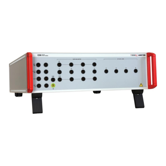
CDN 117A - series
CDN 117A-C4-4-1
CDN 117A-C6-4-1
Coupling network for Surge and
Ring wave to signal and datalines
The coupling network of the CDN 117A series are designed for
coupling ringwave, surge- or telecom pulses to signal or data-
lines.
The coupling network expands the range of application of the
impulse generator of the NSG 3040A and NSG 3060A series,
for testing signal and datalines.
Main characteristics are the advantages for handling and the
easy using with banana plugs.
Version: 1.00 / 22.05.2019
Replaces: No previous version Based on DCD sr
Filename: UserManual-NSG 117A-Serie-E-V1.00.doc
Printdate: 22.05.19
IEC 61000-4-5
IEC 61000-4-12
EN 61000-4-5
EN 61000-4-12
Advertisement
Table of Contents

Related Manuals for Ametek CDN 117A Series


Summary of Contents for Ametek CDN 117A Series
- Page 1 Coupling network for Surge and Ring wave to signal and datalines IEC 61000-4-5 IEC 61000-4-12 The coupling network of the CDN 117A series are designed for EN 61000-4-5 coupling ringwave, surge- or telecom pulses to signal or data- EN 61000-4-12 lines.
- Page 2 4153 Reinach BL1 Switzerland Phone: +41 61 204 41 11 Fax: +41 61 204 41 00 URL: http://www.teseq.com Copyright © 2019 AMETEK CTS GmbH. All right reserved. Information in earlier versions. Specifications subject to change Operation Manual V 1.00 2 / 30...
-
Page 3: Table Of Contents
Testing and danger ..........................6 2.2.1. Coupling networks ..........................6 2.2.2. Danger from EUT ..........................6 Standards for testing with coupling networks of CDN 117A series ......7 3.1. Description ............................7 3.2. Coupling- decoupling network models ....................8 3.3. -
Page 4: General
AMETEK CTS CDN 117A series General 1.1. Intended use Coupling decoupling networks of the CDN 117A seriesare used for simulating conducted electromagnetic inter- ference effects for immunity testing to international, national, and manufacturers’ standards. The CDN’s are designed for full compliance conducted electromagnetic compatibility (EMC) test requirements. -
Page 5: Safety
AMETEK CTS CDN 117A series Safety 2.1. Safety aspects Read the following operation manual carefully. Pay special attention to both safety and operation details!!! Observe all of these precautions to ensure your personal safety and to prevent damage to the test equipment. -
Page 6: Testing And Danger
AMETEK CTS CDN 117A series 2.2. Testing and danger All tests offered by the High Voltage or EMC generators are immunity tests on electronic equipment or devices. These tests are potentially dangerous for the operator. Therefore, it is the responsibility of the user to avoid critical failures and risks to the environment and operator. -
Page 7: Standards For Testing With Coupling Networks Of Cdn 117A Series
AMETEK CTS CDN 117A series Standards for testing with coupling networks of CDN 117A series The coupling network CDN 117A seriesare suitable for testing the following standards: IEC 61000-4-5 Surge 1.2/50s with capacitor and gas arrestor Ring wave IEC 61000-4-12 The figures below show the setup as per the applied standards. -
Page 8: Coupling- Decoupling Network Models
AMETEK CTS CDN 117A series 3.2. Coupling- decoupling network models Following coupling decoupling network for signal and data lines exis: Coupling Model Signal EUT current Test level max. 0.5µF > 3 µF lines max.* arrestor CDN 117A C4-4-1 4 wires 4.8 kV 1.2/50us... -
Page 9: Device Functions And Operating
AMETEK CTS CDN 117A series Device functions and operating The difference between the various models is: Number of data lines (CDN 117A Cx-4-1 series with 4 lines nominal voltage and current level of the signal- and data lines various test voltage level of 4.8 kV and 6.6 kV 4.1. -
Page 10: Coupling Line To Line
AMETEK CTS CDN 117A series 4.2. Coupling Line to Line Coupling with 40 resistor and 0.5 µF capacitor 4.2.1. Example for coupling as per IEC 61000-4-5 Capacitive with 0.5 µF and 40 resistor Coupling: Coupling Path: Line L1 (S2) to Line L3 (S1) 4.2.2. -
Page 11: Coupling With External Coupling Device
AMETEK CTS CDN 117A series 4.2.3. Coupling with external coupling device Example for coupling as per IEC 61000-4-5 Coupling: Ecternal coupling device, designed by the user Coupling Path: Line L2 (S2) to Line L4 (S1) The external coupling device requires the following components... -
Page 12: Coupling To Gnd
AMETEK CTS CDN 117A series 4.3. Coupling to GND 4.3.1. Test setup Coupling to PE Example for coupling as per IEC 61000-4-5 Capacitive with 0.5 µF and 40 resistor Coupling: Coupling Path: Line L1 (S2) protected earth PE (S1) Operation Manual V 1.00... -
Page 13: Test Setup For Cdn 117A Series Application
The device earth bolt must be connected to the ground reference plane, if there is one. In other case user is responsible that the generator earth bolt is proper connected with the building earth. Connection HV – COM (impulse cable generator – CDN 117A series) Twisted cable (HV and COM) -
Page 14: Technical Data Cdn 117A Series
AMETEK CTS CDN 117A series Technical data CDN 117A series 5.1. Technical data na= no application * max intermittent current for 4 A models = 5 A, for 20 minutes, pause 20 minutes Line coupling For coupling line to line and line to GND... -
Page 15: Ae Protection For Auxiliary Equipment
AMETEK CTS CDN 117A series 5.3. AE Protection for auxiliary equipment Application Depends on the application different protection units are awailable to pro- tect the auxiliary equipment. The protection unit is changeable to get the best protection for the auxiliary... - Page 16 AMETEK CTS CDN 117A series V/I characteristics v = f (i) - for explanation of the characteristics refer to "General technical information", 1.6.3 A = Leakage current, B = Protection level for worst-case varistor tolerances Operation Manual V 1.00 16 / 30...
- Page 17 AMETEK CTS CDN 117A series 5.3.2. DPM 50 and DPM 50-1 The Protection module DPM 50 and DPM 50-1 includes two transil diodes, provide high overvoltage protection by clamping action. With a peake pulse power of 5000 W (10/1000 μs)
-
Page 18: Maintenance
AMETEK CTS equipment. AMETEK CTS doesn’t know each customer’s Quality Assurance policy, nor do we know how often the equip- ment is used and what kind of tests is performed during the life cycle of test equipment. Only the customer knows all the details and therefore the customer needs to specify the calibration interval for his test equipment. -
Page 19: Maintenance, Adjustments, Replacement Of Parts
• The user is not permitted to change or modify any AMETEK CTS generator. Only original AMETEK CTS parts and components shall be used for repair and service. AMETEK CTS is not responsible for accidents or injuries caused through the use of parts or components not sold by AMETEK CTS •... -
Page 20: Calibration Procedure As Per Iec 61000-4-5 Ed3
AMETEK CTS CDN 117A series 6.4. Calibration procedure as per IEC 61000-4-5 Ed3 6.4.1. General It is recommended and sufficient to calibrate the CDNs for interconnection lines in the same configuration that will be used for testing. The residual surge voltage measured between the surged lines and ground on the AE side of the CDN, with the EUT and AE equipment disconnected, shall be measured and recorded so that users of the CDN may determine if the protection is sufficient for use with a particular AE. -
Page 21: Surge Waveform Definition
AMETEK CTS CDN 117A series The intention of this calibration process is to check the proper function of the components, the saturation of de- coupling chokes, the decoupling effect of the decoupling part, the current capability and the coupling effect of the coupling network part. -
Page 22: Kalibrationsprozedur Gem. Iec 61000-4-12 Ed.3
AMETEK CTS CDN 117A series 6.5. Kalibrationsprozedur gem. IEC 61000-4-12 Ed.3 6.5.1. Ringwave Impulsformdefinition gem. IEC 6100-4-12 Ed.3 Parameter voltage rise time T 0,5 µs ± 30 % (open-circuit) ≤1 µs (short-circuit) current rise time T voltage osc frequency: 100 kHz ± 10 %;... -
Page 23: Delivery Groups
Identical accessory parts are delivered only once if several devices are ordered. The delivered packing list is in each case valid for the delivery. 7.1. Delivery groups CDN 117A series coupling network • Base equipment DCD sr all models •... -
Page 24: Appendix
CE directives listed below using the relevant section of the following EC standards and other normative documents. Product‘s name: CDN 117A series coupling decoupling network for surge & Ringw wave pulses Model Number(s) NSG 117A C4-4-1, NSG 117A C6-4-1... -
Page 25: Diagram Cdn 117A Series
AMETEK CTS CDN 117A series 8.2. Diagram CDN 117A series CDN 117A Cx-4-1 Operation Manual V 1.00 25 / 30... -
Page 26: Typical Waves
AMETEK CTS CDN 117A series 8.3. Typical waves The measurements below shows a typical waveform recorded with a DCD model 8.3.1. Surge coupling Typical surge pulses with 4000V charging voltage of the hybrid generator with an impedance of 2Ω Coupling L1 – L2; 4000V, open circuit Coupling L1-GND;... -
Page 27: Ringwave Coupling 12 Ω Generator Impedance
AMETEK CTS CDN 117A series Ringwave coupling 12 Ω generator impedance 8.3.2. Typical Ringwave pulses with 4000V charging voltage with an impedance of 12Ω, Coupling L1 – L2; 4000V, open circuit Coupling L1 – GND; 4000V, open circuit Coupling L1 – L2; 4000V, short circuit Coupling L1 –... -
Page 28: Ringwave Coupling 30 Ω Generator Impedance
AMETEK CTS CDN 117A series Ringwave coupling 30 Ω generator impedance 8.3.3. Typical Ringwave pulses with 4000V charging voltage with an impedance of 30 Ω, Coupling L1 – L2; 4000V, open circuit Coupling L1 – GND; 4000V, open circuit Coupling L1 – L2; 4000V, short circuit Coupling L1 –... -
Page 29: Residual Voltage Measurements At The Ae Port
AMETEK CTS CDN 117A series 8.3.4. Residual voltage measurements at the AE port The diagrams shown are typical for the standard coupling/decoupling network CDN 117A model. The diagram shows volt- age impulses with different couplings and 4000V impulse open circuit waveshape at the AE Port Residual voltage with capacitive coupling, Pulse 1,2/50 s... -
Page 30: Transfer Function In Function With The Eut Impedance
AMETEK CTS CDN 117A series 8.4. Transfer function in function with the EUT Impedance The figure below illustrates the transfer function respective the voltage drops over the inductances of the cou- pling network (2x20 mH). The graph shows the influence of different UET impedances. Is only one inductance used, the voltage drop is reduceing and the ratio is to recalculate.
Need help?
Do you have a question about the CDN 117A Series and is the answer not in the manual?
Questions and answers