Table of Contents
Advertisement
Quick Links
Advertisement
Table of Contents
Troubleshooting

Related Manuals for DEWESOFT SIRIUS Series


Summary of Contents for DEWESOFT SIRIUS Series
- Page 1 SIRIUS ® TECHNICAL REFERENCE MANUAL SIRIUS ® V20-1 ...
-
Page 2: Table Of Contents
11 2.1. Legend 11 2.2. Online versions 12 2.2.1. SIRIUS® Technical Reference Manual 12 2.2.2. DEWESoft® User Manual 12 3. Getting started 13 3.1. Software installation 13 3.2. Connecting a single slice 14 ... - Page 3 SIRIUS ® TECHNICAL REFERENCE MANUAL 4.3.3.1. RTK 44 4.4. Connectors 44 4.4.1. General 45 4.4.1.1. USB Connector 45 4.4.1.2. Power in connector 46 4.4.1.3. Power out connector 46 5.4.1.2. EtherCAT® connector 47 ...
- Page 4 SIRIUS ® TECHNICAL REFERENCE MANUAL 4.10.4. SIRIUS-R4-HUB: Specification 80 4.10.5. SIRIUS-R2/R4: Front side 81 4.10.6. SIRIUS-R2/R4: Rear side 82 4.10.7. SIRIUS-R2-HUB/R4-HUB: Front side 83 4.11. SIRIUS-R8DB 83 4.11.1. SIRIUS-SBOXre 85 4.11.2.
- Page 5 SIRIUS ® TECHNICAL REFERENCE MANUAL 5.1.2.1. Standard EtherCAT® features 124 5.1.2.2. DS-ETHERCAT+ 125 5.1.2.3. EtherCAT® specifications 126 5.1.3. Data transfer combinations 127 5.2. Technology overview 127 5.2.1. SIRIUS® DUAL CORE series: high dynamic (up to 160 dB) 129 ...
- Page 6 SIRIUS ® TECHNICAL REFERENCE MANUAL 5.10.2. HV 1 5.10.2.1. HV: Voltage 157 5.11. LV / LV+ 157 5.11.1. LVv2: Specifications 158 5.11.2. LV 159 5.11.2.1. LV: Voltage 159 5.11.2.2. LV: Current 160 ...
- Page 7 SIRIUS ® TECHNICAL REFERENCE MANUAL 5.14.2.4. STG: Resistance 191 5.14.2.5. STG: Potentiometer 192 5.14.2.6. STG: Bridge 193 5.14.3. STG-L2B7f 193 5.14.3.1. STG-L2B7f: Voltage 195 5.14.3.2. STG-L2B7f: Current 195 5.14.3.3. STG-L2B7f: Temperature 196 ...
- Page 8 SIRIUS ® TECHNICAL REFERENCE MANUAL 5.17.3. HD-STGS-L1B10f 224 5.17.3.1. HD-STGS-L1B10f: Voltage 225 5.17.3.2. HD-STGS-L1B10f: Current 225 5.17.3.3. HD-STGS-L1B10f: Potentiometer 226 5.17.3.4. HD-STGS-L1B10f: Bridge 227 5.18. HS-ACC / HS-ACC+ 228 5.18.1. HS-ACC: Specifications 228 ...
- Page 9 291 6.1.6.2. AAF (zero-phase distortion) 292 6.1.6.3. IIR filters 294 6.1.6.4. FIR filter characteristics 297 6.1.7. DEWESoft®: Custom low pass filter settings 299 7. Accessories 300 8. Advanced Topics 301 8.1. Wireless connection 301 ...
- Page 10 11.2.1. Environmental considerations 330 11.2.2. Product End-of-Life handling 330 11.2.3. System and components recycling 331 11.2.4. General safety and hazard warnings for all Dewesoft systems 331 12. Documentation version history 333 12.1. Previous versions history 334 ...
-
Page 11: About This Document
measurement task. Each system also includes a professional license for our award-winning Dewesoft ... -
Page 12: Online Versions
The latest version of the DEWESoft® tutorials can be found here: https://download.dewesoft.com/list/manuals-brochures/software-manuals In the Software Manuals section click the download link of the DEWESoft X3 User Manual entry. Important Read safety instructions first in chapter Safety instructions ... -
Page 13: Getting Started
PC with Windows 10 ● Note: older versions like Windows® 7 may also work ● 3.1. Software installation For optimal working, we recommend that you install the latest version of Dewesoft. If you already have ... -
Page 14: Connecting A Single Slice
SIRIUS ® TECHNICAL REFERENCE MANUAL 3.2. Connecting a single slice 3.2.1. USB slice First connect the power supply to the connector named POWER IN of your SIRIUS system. SIRIUS USB: connectors on the rear side ... -
Page 15: Ethercat Slice
For the EtherCAT slice a RJ-45 to 8-pin LEMO connector is needed to connect the device to the PC. Connection of single SIRIUS EtherCAT device 3.2.3. Dewesoft settings SIRIUS The connected device will show up in the Dewesoft settings. Click on the Options button at the top ... -
Page 16: Channel Setup Sirius
TECHNICAL REFERENCE MANUAL Dewesoft settings: Device 3.2.4. Channel setup SIRIUS When Dewesoft has started up, you will be in the Measure mode and see the Setup files list or you can ... - Page 17 SIRIUS ® TECHNICAL REFERENCE MANUAL Channel setup SIRIUS Hint When you click on a connector in the image the corresponding channel in the Channel setup ...
-
Page 18: Simple Measurement
measurement setup. 3.3.1. Help - manual Note that this document is just a quick start guide. For detailed information about Dewesoft consult the ... -
Page 19: Sample Rate
SIRIUS will transfer to the Dewesoft. Higher sample rate also means that more data needs to be ... -
Page 20: Measurement Mode
button. Now Dewesoft has created a data file with all the data that you have seen during the recording session. ... -
Page 21: Analyse Mode
SIRIUS ® TECHNICAL REFERENCE MANUAL 3.3.5. Analyse mode When you have just stopped a measurement, Dewesoft will automatically open the last recorded data ... -
Page 22: Advanced Configuration
SIRIUS ® TECHNICAL REFERENCE MANUAL 3.4. Advanced configuration Note, that the Dewesoft launcher has already done the hardware setup for you – you can check this in ... -
Page 23: Firmware Upgrade
(.dxu file) from the Dewesoft downloads page under ● the section Drivers. Copy the file into the Firmwares folder of your Dewesoft installation (e.g. ● D:\DewesoftX\System\X3\Firmwares). Connect the Dewesoft instrument to the PC and run Dewesoft X3. ... -
Page 24: Licensing
SIRIUS ® TECHNICAL REFERENCE MANUAL 3.6. Licensing SIRIUS or any other Dewesoft device already comes with an embedded Dewesoft license. You can check ... -
Page 25: Troubleshooting
If your SIRIUS® device is not found by DEWESoft®: If you did not restart Windows after the software installation, restart now ● Make sure, that you have started DEWESoft® version 7.1 or higher (7.0.x versions do not support ... -
Page 26: Additional Instructions For Troubleshooting With Ethercat Devices
SIRIUS ® TECHNICAL REFERENCE MANUAL 3.7.1. Additional instructions for troubleshooting with EtherCAT devices If the computer is still having trouble recognizing the Dewesoft EtherCAT devices, here are some ... - Page 27 SIRIUS ® TECHNICAL REFERENCE MANUAL If the driver is already installed and the devices are still not recognized, the Speed & Duplex of the ...
-
Page 28: System Overview
SIRIUS ® TECHNICAL REFERENCE MANUAL 4. System Overview SIRIUS The world's most versatile USB and EtherCAT data acquisition system. Any signal, any sensor, packed with cutting edge technology. ... -
Page 29: Main Features
● functionality, award-winning DEWESoft X3 software is included. All upgrades to the software are free forever with no hidden licensing costs. ... - Page 30 SIRIUS ® TECHNICAL REFERENCE MANUAL The SIRIUS® system consists of Slices which contain up to 8 measurement Modules Each SIRIUS® module typically has one analog channel. The HD-series has 2 channels per module. ...
-
Page 31: Naming Of Variants, Suffix Description
SIRIUS ® TECHNICAL REFERENCE MANUAL 4.1.1. Naming of variants, suffix description Important See table below for SIRIUS, Rack and SBOX suffix descriptions / abbreviations. Suffix Device Description i ... -
Page 32: Enclosure Overview
SIRIUS ® TECHNICAL REFERENCE MANUAL 4.2. Enclosure Overview SIRIUS® systems are available in different enclosure types. The following list provides a short high-level ... -
Page 33: Modular Solution
SIRIUS ® TECHNICAL REFERENCE MANUAL 4.2.1. Modular solution A single SIRIUS® slice can have up to 8 measurement modules. Each measurement module has typically one analog channel. Some modules also have an optional ... -
Page 34: Single Slice: Usb
SIRIUS ® TECHNICAL REFERENCE MANUAL 4.2.1.1. Single slice: USB This chapter describes the SIRIUS® USB single slice enclosure. Important The LED indicator on the front side shows system status. LED status ... -
Page 35: Single Slice: Rear Side
SIRIUS ® TECHNICAL REFERENCE MANUAL 4.2.1.2. Single slice: Rear side The SIRIUS® USB chassis has following connectors at the rear side: SIRIUS rear side Name Description CAN CAN bus DSUB-9 male connector SYNC ... -
Page 36: Single Slice: Ethercat
USB Mini the same time to get data rates that are not possible with EtherCAT® alone. Note: when you use multiple slices, then DEWESoft® must be the EtherCAT® master. GND Protective Ground banana plug and M4 screw insert. ... - Page 37 SIRIUS ® TECHNICAL REFERENCE MANUAL USB / Sync / Power / GND are all internally wired to the bottom slice. The bottom slice does of course ...
-
Page 38: Extended Height Enclosure
SIRIUS ® TECHNICAL REFERENCE MANUAL 4.2.3. Extended height enclosure Some modules may require a higher enclosure, depending on the connector type. The extended height enclosures are available for the Single and for the Boxed Solution only (not for ... -
Page 39: Rack Enclosure
SIRIUS ® TECHNICAL REFERENCE MANUAL 4.2.4. Rack enclosure SIRIUS Slices are also available as modular rack system versions. Important Notes for the rack series: SIRIUSr Rack slices can be changed between different Rack enclosures (R2, R4, R3, R8). ●... -
Page 40: Mini Enclosure
SIRIUS ® TECHNICAL REFERENCE MANUAL 4.2.5. Mini enclosure SIRIUS MINI is a small and highly portable, USB powered data acquisition system ideal for acoustic, ... -
Page 41: Miscellaneous
SIRIUS ® TECHNICAL REFERENCE MANUAL 4.3. Miscellaneous 4.3.1. Click mechanism You can use the SIRIUS slices independently or combine them to a single fully-synchronised ... -
Page 42: Usb Hubs Vs. Native Ports
SIRIUS ® TECHNICAL REFERENCE MANUAL 4.3.2. USB hubs vs. native ports USB, short for Universal Serial Bus, is an industry standard that defines the cables, connectors and ... -
Page 43: Gps Option
SIRIUS ® TECHNICAL REFERENCE MANUAL 4.3.3. GPS option The table shows the specifications of the optional GNSS receivers that you can order for your SBOX ... -
Page 44: Rtk
to get an accuracy of 2 cm. For details, please refer to the “RTK Manual” on our download page: http://www.dewesoft.com/downloads Upgrading to RTK When your SBOX already has a 100 Hz GPS receiver the upgrade to the 100 Hz + RTK Option can easily ... -
Page 45: Connectors
receptacles. Hint DEWESoft® USB cables have thumb screws to the right and left of the connector so that you can ... -
Page 46: Power In Connector
SIRIUS ® TECHNICAL REFERENCE MANUAL 4.4.1.2. Power in connector Pin Name Description 1 V + Supply 2 V - Ground Power in connector: pin-out (2-pin LEMO male) Power In connector (on the device): EXJ.1B.302.CLA ... -
Page 47: Ethercat® Connector
SIRIUS ® TECHNICAL REFERENCE MANUAL 5.4.1.2. EtherCAT® connector The EtherCAT® connector can provide power and transfer the measurement data plus synchronisation signal in one single cable. SIRIUS® EtherCAT® slices have 2 connectors, so that you can easily chain ... -
Page 48: Ethercat® Slave Port
system while the Internal bus allows full-speed data recording to Dewesoft X software in parallel, serving ... -
Page 49: Sync Connector
SIRIUS ® TECHNICAL REFERENCE MANUAL 4.4.1.6. SYNC connector Sync cable The sync connectors are required when you want to use multiple SIRIUS® USB slices for the same ... -
Page 50: Can
SIRIUS ® TECHNICAL REFERENCE MANUAL 4.4.1.7. CAN A Controller Area Network (CAN bus) is a vehicle bus standard often used in automotive applications. ... -
Page 51: Sbox Common Connectors
SIRIUS ® TECHNICAL REFERENCE MANUAL 4.4.2. SBOX common connectors 4.4.2.1. GPS connector (DSUB-9) Used for connecting RTK modem or display: External VGPS-DISP can be connected to receive and display NMEA parameters if internal GNSS ... -
Page 52: Gps Antenna Connector
SIRIUS ® TECHNICAL REFERENCE MANUAL 4.4.2.2. GPS antenna connector GPS is only available when you have an SBOX with GPS Option. Connect the GPS Antenna to the GPS ANT RP-SMA Female Jack connector and make sure that there is ... -
Page 53: Sboxre Power In Connector
SIRIUS ® TECHNICAL REFERENCE MANUAL 4.4.2.4.2. SBOXre power in connector Pin Name Description 1 V + Supply 2 GND Ground Power in connector: pin-out (2-pin LEMO male) ... -
Page 54: Remote On
Remote-On pin. To power off the system press the Power switch or reduce the voltage on Remote-On below 0.5 V for more than one second. Remote on functionality can be set to various options, see details below. DEWESoft settings, SBOX system ... -
Page 55: Sirius-Sbox
SIRIUS ® TECHNICAL REFERENCE MANUAL 4.5. SIRIUS-SBOX The SIRIUS-SBOX is an integrated powerful PC in a rugged SIRIUS® chassis: with an Intel® Core™ ... -
Page 56: Sirius-Sboxe/Fe: Specifications
SIRIUS ® TECHNICAL REFERENCE MANUAL 4.5.1. SIRIUS-SBOXe/fe: Specifications The SIRIUS-SBOXe version is an SBOX with EtherCAT® interface. It is available in the Modular Solution ... -
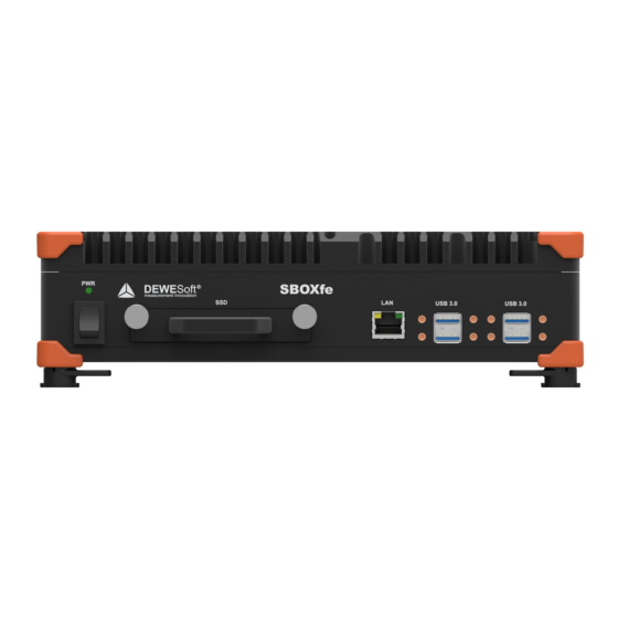
Page 57: Sirius-Sboxe: Front Side
SIRIUS ® TECHNICAL REFERENCE MANUAL 4.5.2. SIRIUS-SBOXe: Front side SIRIUS-SBOXe: Connectors at the front side Name Description USB 3.0 4 x USB 3.0 connector LAN 1x GLAN Ethernet, RJ45 connector SSD ... -
Page 58: Sirius-Sboxe: Rear Side
SIRIUS ® TECHNICAL REFERENCE MANUAL 4.5.3. SIRIUS-SBOXe: Rear side SIRIUS-SBOXe: Connectors at the rear side Name Description POWER 9-36V 3-pin LEMO male connector POWER OUT 2-pin LEMO female connector GPS ... -
Page 59: Sirius-Sboxfe: Front Side
SIRIUS ® TECHNICAL REFERENCE MANUAL 4.5.4. SIRIUS-SBOXfe: Front side The SIRIUS-SBOXfe version is an SBOX with EtherCAT® interface. It is available for the Modular Solution. ... -
Page 60: Sirius-Sboxfe: Rear Side
SIRIUS ® TECHNICAL REFERENCE MANUAL 4.5.5. SIRIUS-SBOXfe: Rear side SIRIUS-SBOXfe Rear side Name Description SYNC 4-pin LEMO female sync connector EtherCAT 8-pin LEMO female connector DVI-D ... -
Page 61: Sirius-Sboxwe
SIRIUS ® TECHNICAL REFERENCE MANUAL 4.6. SIRIUS-SBOXwe Extremely rugged data logger and powerful data processing computer with IP67 degree of protection and wide temperature rating of -40 °C to +50 °C. -
Page 62: Sirius-Sboxwe: Front Side
SIRIUS ® TECHNICAL REFERENCE MANUAL 4.6.2. SIRIUS-SBOXwe: Front side SIRIUS-SBOXwe Front side Name Description PWR LED light Green when Power is available and switch on PWR switch Power On rocker switch ... -
Page 63: Sirius-Sboxwe: Rear Side
SIRIUS ® TECHNICAL REFERENCE MANUAL 4.6.3. SIRIUS-SBOXwe: Rear side SIRIUS-SBOXwe Rear side Name Description SYNC 4-pin LEMO female sync connector EtherCAT 8-pin LEMO female connector DVI-D DVI video out (VGA and HDMI compatible) ... -
Page 64: Sirius-Waterproof
SIRIUS ® TECHNICAL REFERENCE MANUAL 4.7. SIRIUS-Waterproof 4.7.1. SIRIUSiwe: Front side SIRIUSiwe front side Name Description PWR LED light Green when Power is available and switch on CNT ... -
Page 65: Siriusiwe: Rear Side
SIRIUS ® TECHNICAL REFERENCE MANUAL 4.7.2. SIRIUSiwe: Rear side SIRIUSiwe Rear side Name Description EtherCAT IN EtherCAT® port 8-pin LEMO male connector EtherCAT OUT EtherCAT® port 8-pin LEMO female connector ... -
Page 66: Sirius-R1Db/R2Db Mobile Data Acquisition System
SIRIUS ® TECHNICAL REFERENCE MANUAL 4.8. SIRIUS-R1DB/R2DB Mobile Data Acquisition System Compact, mobile data acquisition systems with a built-in data logger, powerful data processing ... - Page 67 SIRIUS ® TECHNICAL REFERENCE MANUAL R1DB is a smaller, even more compact version of R2DB data acquisition system. It features the same ...
-
Page 68: Sirius-Sboxse: Specifications
SIRIUS ® TECHNICAL REFERENCE MANUAL 4.8.1. SIRIUS-SBOXse: Specifications Computer Processor Intel® Core™ i3; 2x 2.3 GHz base; 4 threads Memory 8 GB (optional up to 32 GB) Storage Non-removable M2 500GB (1 TB as option) Interfaces and options ... -
Page 69: Sirius-R1Db: Specifications
SIRIUS ® TECHNICAL REFERENCE MANUAL 4.8.2. SIRIUS-R1DB: Specifications Display Type 12.1'' TFT Touch Screen PCAP, Multi-touch Resolution WXGA, 1280 x 800 pixels @ 60 Hz Brightness 700 cd/m² Batteries ... - Page 70 SIRIUS ® TECHNICAL REFERENCE MANUAL Hint A version without display is also available (R1B). All-In-One instrument for one SIRIUSr slice, SBOXse and two hot swappable batteries with integrated Battery Management System.
-
Page 71: Sirius-R2Db: Specifications
SIRIUS ® TECHNICAL REFERENCE MANUAL 4.8.3. SIRIUS-R2DB: Specifications Display Type 12.1'' TFT Touch Screen PCAP, Multi-touch Resolution WXGA, 1280 x 800 pixels @ 60 Hz Brightness 700 cd/m² Batteries ... -
Page 72: Sirius Sboxse R1Db/R2Db: Front Side
SIRIUS ® TECHNICAL REFERENCE MANUAL 4.8.4. SIRIUS SBOXse R1DB/R2DB: Front side SIRIUS-R1DB / R2DB Front side On the front side of the SIRIUS-R1DB/R2DB you can find these connectors: Name Description ... -
Page 73: Sirius-R3
SOFTWARE INCLUDED WITH FREE LIFETIME UPGRADES: Easy to use and rich in functionality, ● our award-winning Dewesoft X software is included with every R3 instrument. Dewesoft X is not only the best DAQ software but also offers lifetime FREE software upgrades. ... -
Page 74: Sirius-R3: Specifications
SIRIUS ® TECHNICAL REFERENCE MANUAL 4.9.1. SIRIUS-R3: Specifications Computer Processor Intel® Core™ i7-8700; 6 cores, 12 threads; 3.2 GHz base, 4.6 GHz max Memory 8 GB (optional up to 128 GB) Storage ... -
Page 75: Sirius-R3: Front Side
SIRIUS ® TECHNICAL REFERENCE MANUAL 4.9.2. SIRIUS-R3: Front side SIRIUS-R3 front side (with 3 SIRIUSr-8xLV) Name Description USB 3.0 2x USB 3.0 PWR switch To switch PC on or off. DISK 1 / 2 ... -
Page 76: Sirius-R2/R4
SIRIUS ® TECHNICAL REFERENCE MANUAL 4.10. SIRIUS-R2/R4 R2/R4 is a compact data acquisition system with up to 64 analog inputs, 32 counter inputs and 32 ... -
Page 77: Sirius-R2: Specifications
SIRIUS ® TECHNICAL REFERENCE MANUAL 4.10.1. SIRIUS-R2: Specifications Computer Processor Intel® Core™ i7; 2x 2.6 GHz base, 3.4 GHz max; 4 threads Memory 8 GB (optional up to 32 GB) Storage ... -
Page 78: Sirius-R2-Hub: Specifications
SIRIUS ® TECHNICAL REFERENCE MANUAL 4.10.2. SIRIUS-R2-HUB: Specifications Interfaces and options USB Front 1x USB 2.0, USB Mini B Synchronisation 2x SIRIUS® SYNC USB 2.0 hub Bandwidth Minimum 20 MB/sec Typical 25 MB/sec ... -
Page 79: Sirius-R4: Specification
SIRIUS ® TECHNICAL REFERENCE MANUAL 4.10.3. SIRIUS-R4: Specification Computer Processor Intel® Core™ i7; 2x 2.6 GHz base, 3.4 GHz max; 4 threads Memory 8 GB (optional up to 32 GB) Storage ... -
Page 80: Sirius-R4-Hub: Specification
SIRIUS ® TECHNICAL REFERENCE MANUAL 4.10.4. SIRIUS-R4-HUB: Specification Interfaces and options USB Front 1x USB 2.0, USB Mini B Synchronisation 2x SIRIUS® SYNC USB 2.0 hub Bandwidth Minimum 20 MB/sec Typical 25 MB/sec ... -
Page 81: Sirius-R2/R4: Front Side
SIRIUS ® TECHNICAL REFERENCE MANUAL 4.10.5. SIRIUS-R2/R4: Front side SIRIUS-R4 Front side (SBOX R4) On the front side of the SIRIUS-R4 or SBOXse you can find these connectors: Name Description LAN ... -
Page 82: Sirius-R2/R4: Rear Side
SIRIUS ® TECHNICAL REFERENCE MANUAL 4.10.6. SIRIUS-R2/R4: Rear side SIRIUS-R4 Rear side On the back side of the SIRIUS-R4 you can find these connectors: Name Description AO 1 to 8 Analog out BNC connectors (optional) ... -
Page 83: Sirius-R2-Hub/R4-Hub: Front Side
SIRIUS ® TECHNICAL REFERENCE MANUAL 4.10.7. SIRIUS-R2-HUB/R4-HUB: Front side SIRIUS-R4-HUB Name Description SYNC 2x 4-pin LEMO male sync connector GND Protective Ground banana plug and screw connector ... -
Page 84: Sirius-R8Db
SIRIUS ® TECHNICAL REFERENCE MANUAL 4.11. SIRIUS-R8DB High channel count data acquisition system with built-in data logger and powerful data processing computer, touch screen display (R8D) and internal batteries (R8B, R8DB) for maximum portability. -
Page 85: Sirius-Sboxre
SIRIUS ® TECHNICAL REFERENCE MANUAL Hint The analog out option is available only on SIRIUS-R8B and SIRIUS-R8. 4.11.1. SIRIUS-SBOXre At the heart of every R8 DAQ system is a powerful SBOX computer powered by Intel Core i7 CPU. ... - Page 86 SIRIUS ® TECHNICAL REFERENCE MANUAL SBOXre SBOXre-2GLAN SIRIUS V20-1 86 / 336 ®...
- Page 87 SIRIUS ® TECHNICAL REFERENCE MANUAL On the front side of the SBOXre you can find these connectors: Name Description LAN 1 (SBOXre) or 2 Ethernet (SBOXre-2GLAN) 1 Gbps, RJ45 connector WLAN ANT RP-SMA Female WLAN antenna: WiFi 802.11 b/g/n (not for SBOXre-2GLAN) ...
-
Page 88: Sirius-R8: Specifications
SIRIUS ® TECHNICAL REFERENCE MANUAL 4.11.2. SIRIUS-R8: Specifications R8 R8B R8D R8DB Computer Processor Intel® Core™ i7; 4x 2.0 GHz base, 2.8 GHz max; 8 threads Memory 8 GB (optional up to 32 GB) ... - Page 89 SIRIUS ® TECHNICAL REFERENCE MANUAL Operating Temperature -10 to 50 °C 0 to 40 °C -10 to 50 °C 0 to 40 °C Storage Temperature -40 to 85 °C -20 to 60 °C ...
-
Page 90: Sirius-R8Rt: Specifications
SIRIUS ® TECHNICAL REFERENCE MANUAL 4.11.3. SIRIUS-R8rt: Specifications Computer Processor Intel® Core™ i7; 4x 2.0 GHz base, 2.8 GHz max; 8 threads Memory 8 GB (optional up to 32 GB) 250 GB removable SATA SSD ... -
Page 91: Sirius-R8Db: Front Side
SIRIUS ® TECHNICAL REFERENCE MANUAL 4.11.4. SIRIUS-R8DB: Front side SIRIUS-R8DB, SIRIUS-R8B, SIRIUS-R8D or SIRIUS-R8 Front side Hint Connectors on the front side are the connectors from SBOXre and selected modules. For a more detailed description of the connectors please refer to the section “SIRIUS-SBOXre”. -
Page 92: Sirius-R8: Rear Side
SIRIUS ® TECHNICAL REFERENCE MANUAL 4.11.5. SIRIUS-R8: Rear side SIRIUS-R8 EXT CAL SIRIUS-R8 Analog Out SIRIUS-R8rt SIRIUS V20-1 92 / 336 ®... - Page 93 SIRIUS ® TECHNICAL REFERENCE MANUAL Name Description EXT CAL R8 system features (optional) cal reference input. External calibration reference can be connected via single BNC connector on the rear side of the R8 and can be switched in the software to all input channels at once to check the amplifier performance and accuracy.
-
Page 94: Sirius-R8Db: Rear Side
SIRIUS ® TECHNICAL REFERENCE MANUAL 4.11.6. SIRIUS-R8DB: Rear side SIRIUS-R8DB or SIRIUS-R8D Rear side Name Description USB 3.0 3x USB 3.0 USB 2.0 1x USB 2.0 PWR switch ... -
Page 95: Siriusm
SIRIUS ® TECHNICAL REFERENCE MANUAL 4.12. SIRIUSm Main features: SMALLEST DAQ: SIRIUS mini is our smallest, 4-channel data acquisition system, mainly suitable ... - Page 96 SIRIUS ® TECHNICAL REFERENCE MANUAL SIRIUSm-4xACC SIRIUS V20-1 96 / 336 ®...
-
Page 97: Siriusm: Specifications
SIRIUS ® TECHNICAL REFERENCE MANUAL 4.12.1. SIRIUSm: Specifications SIRIUSm-4xACC SIRIUSm-3xACC-1xACC+ Analog inputs Input type Voltage Voltage IEPE IEPE ADC type 24-bit delta-sigma dual core with anti-aliasing filter 24-bit delta-sigma dual core with anti-aliasing filter Sampling rate ... - Page 98 SIRIUS ® TECHNICAL REFERENCE MANUAL Power supply 5.0 V (+0.25 V, -0.6 V) DC Power consumption Data USB port: Max. 2.5 W Power USB port: Typ. 2.5 W, Max. 6 W Environmental ...
-
Page 99: Minitaurs
SIRIUS ® TECHNICAL REFERENCE MANUAL 4.13. MINITAURs Mixed signal data acquisition system and multichannel data logger with cutting-edge technology at an ... -
Page 100: Minitaurs: Specifications
SIRIUS ® TECHNICAL REFERENCE MANUAL 4.13.1. MINITAURs: Specifications Analog inputs Inputs 8 ch voltage Full / Half / Quarter bridge strain ADC type 24-bit delta-sigma DUALCOREADC® with anti-aliasing filter Sampling rate ... - Page 101 SIRIUS ® TECHNICAL REFERENCE MANUAL USB Front: 4x USB 3.0 Rear: 2x USB 2.0 Ethernet Front: 1x GLAN (RJ45) Back: 1x GLAN (RJ45), 1x WLAN (RP-SMA Female Jack) EtherCAT® 1x EtherCAT®...
-
Page 102: Connections Examples
When connecting two SIRIUS USB devices to a PC, an additional synchronisation cable is required. Connecting two SIRIUS USB to PC List of required cables: Function Dewesoft order code Power supply PS-120-L1B2f Supply daisy chain L1B2m-L1B2f Synchronization L00B4m-L00B4m ... -
Page 103: Ethercat
SIRIUS ® TECHNICAL REFERENCE MANUAL 4.14.1.2. EtherCAT When using only DeweSoft EtherCAT devices (KRYPTON, SIRIUSe or IOLITE), the connection is straightforward via ECAT to ECAT cable. ... -
Page 104: Combining Ethercat And Usb Chain
Synchronizing data from USB and ECAT data lines with Sync junction List of required cables: Function Dewesoft order code Power supply KRYPTON: PS-120-L1T8m, SIRIUS: PS-120-L1B2f Ethercat EtherCAT to EtherCAT: L1T8m-L1T8f, ... -
Page 105: Rack System With Ethercat
EtherCAT devices. Connection between R4 and SIRIUSe List of required cables: Function Dewesoft order code Power supply PS-200-L2T3F Ethercat EtherCAT to EtherCAT: L1T8m-L1T8f ... -
Page 106: Mixed System
A mixed system with a built-in sync junction List of required cables: Function Dewesoft order code Power supply PS-120-L1B2f Supply Daisy chain L1B2m-L1B2f Ethercat EtherCAT to EtherCAT: L1T8m-L1T8f, ... -
Page 107: Dimensions
SIRIUS ® TECHNICAL REFERENCE MANUAL 4.15. Dimensions 4.15.1. Dimensions: SIRIUS All solutions (Modular Solution, Boxed Solution, SBOX) have the same depth. Dimensions: Single slice (modular solution) ... -
Page 108: Dimensions: Sbox
SIRIUS ® TECHNICAL REFERENCE MANUAL 4.15.2. Dimensions: SBOX Dimensions: SBOXe SIRIUS V20-1 108 / 336 ®... - Page 109 SIRIUS ® TECHNICAL REFERENCE MANUAL Dimensions: SBOXfe SIRIUS V20-1 109 / 336 ®...
-
Page 110: Dimensions: Siriuswe
SIRIUS ® TECHNICAL REFERENCE MANUAL 4.15.3. Dimensions: SIRIUSwe Dimensions: SIRIUSiwe SIRIUS V20-1 110 / 336 ®... -
Page 111: Dimensions: Siriuswe
SIRIUS ® TECHNICAL REFERENCE MANUAL 4.15.4. Dimensions: SIRIUSwe Dimensions: SBOXwe SIRIUS V20-1 111 / 336 ®... -
Page 112: Dimensions: Modular Solution
SIRIUS ® TECHNICAL REFERENCE MANUAL 4.15.5. Dimensions: Modular solution Dimensions: Modular solution SIRIUS V20-1 112 / 336 ®... -
Page 113: Dimensions: Boxed Solution
SIRIUS ® TECHNICAL REFERENCE MANUAL 4.15.6. Dimensions: Boxed solution Dimensions: Boxed solution SIRIUS ® V20-1 113 / 336 ... -
Page 114: Dimensions: R1Db
SIRIUS ® TECHNICAL REFERENCE MANUAL 4.15.7. Dimensions: R1DB Dimensions: SIRIUS-R1 SIRIUS V20-1 114 / 336 ®... -
Page 115: Dimensions: R2Db, R2D
SIRIUS ® TECHNICAL REFERENCE MANUAL 4.15.8. Dimensions: R2DB, R2D Dimensions: SIRIUS-R2 SIRIUS V20-1 115 / 336 ®... -
Page 116: Dimensions: R3
SIRIUS ® TECHNICAL REFERENCE MANUAL 4.15.9. Dimensions: R3 Dimensions: SIRIUS-R3 SIRIUS V20-1 116 / 336 ®... -
Page 117: Dimensions: R4
SIRIUS ® TECHNICAL REFERENCE MANUAL 4.15.10. Dimensions: R4 Dimensions: SIRIUS-R4 SIRIUS V20-1 117 / 336 ®... -
Page 118: Dimensions: R8
SIRIUS ® TECHNICAL REFERENCE MANUAL 4.15.11. Dimensions: R8 Dimensions: SIRIUS-R8 SIRIUS ® V20-1 118 / 336 ... -
Page 119: Dimensions: R8D
SIRIUS ® TECHNICAL REFERENCE MANUAL 4.15.12. Dimensions: R8D Dimensions: SIRIUS-R8D SIRIUS ® V20-1 119 / 336 ... -
Page 120: Rack Mounting
SIRIUS ® TECHNICAL REFERENCE MANUAL 4.15.12.1. Rack mounting Front Handle Aluminium: Screw M5x10 TX RF 19'' Bracket: Screw M4X8 TX RF Dimensions: SIRIUS-R8 rack mounting ... -
Page 121: Dimensions: R8Db
SIRIUS ® TECHNICAL REFERENCE MANUAL 4.15.13. Dimensions: R8DB Dimensions: SIRIUS-R8DB SIRIUS ® V20-1 121 / 336 ... -
Page 122: Dimensions: Mini
SIRIUS ® TECHNICAL REFERENCE MANUAL 4.15.14. Dimensions: MINI Dimensions: SIRIUSm SIRIUS V20-1 122 / 336 ®... -
Page 123: Dimensions: Minitaurs
SIRIUS ® TECHNICAL REFERENCE MANUAL 4.15.15. Dimensions: MINITAURs Dimensions: MINITAURs SIRIUS V20-1 123 / 336 ®... -
Page 124: Sirius® Measurement Modules
Data-throughput allows for sampling rates up to 20 kS/s ● direct connection to standard Ethernet port on the PC possible DS-EtherCAT+ ● ● this is a Dewesoft enhancement to the EtherCAT® standard, so that we can combine the ... -
Page 125: Standard Ethercat® Features
required Weak points of standard EtherCAT®: Master sends the empty message train i.e. when DEWESoft® is the master and does not send ... -
Page 126: Ds-Ethercat
that all data can still be accessed, even if the Master (i.e. DEWESoft® on Windows®) is a little late. ● Synchronisation: DEWESoft® EtherCAT® devices can acquire the samples at an exact time ... -
Page 127: Ethercat® Specifications
Single cable for data, power and sync, daisy chainable 5.1.3. Data transfer combinations DEWESoft® can only acquire data from Dewesoft Hardware which uses the DS-EtherCAT+ protocol. The SIRIUS EtherCAT® slices have 2 modes of operation: ●... -
Page 128: Technology Overview
SIRIUS ® TECHNICAL REFERENCE MANUAL 5.2. Technology overview Module Each SIRIUS® slice can contain up to 8 measurement modules. The illustration below “SIRIUS-HD ... -
Page 129: Sirius® Dual Core Series: High Dynamic (Up To 160 Db)
and therefore clipped. Dewesoft DUAL CORE ADC technology always gives you the full possible ... -
Page 130: Sirius®-Hd Series: High Density (16 Channel Per Slice)
SIRIUS ® TECHNICAL REFERENCE MANUAL 5.2.2. SIRIUS®-HD series: high density (16 channel per slice) For highest channel density this solution offers 24-bit resolution with up to 200 kS/sec sample rate. Important The 2 amplifiers of the HD-modules share a common GND and are isolated against all other ... -
Page 131: Sirius®-Hs Series: High Speed And Bandwidth
SIRIUS ® TECHNICAL REFERENCE MANUAL 5.2.3. SIRIUS®-HS series: high speed and bandwidth This series combines high bandwidth with alias free acquisition with 16-bit of up to 1 MS/sec acquisition ... -
Page 132: Isolated Version: Ethercat
SIRIUS ® TECHNICAL REFERENCE MANUAL 5.2.4. Isolated version: EtherCAT® The basic concept is the same as on the isolated USB version but the EtherCAT® slices do not have CAN ... -
Page 133: Isolated Version: Usb
SIRIUS ® TECHNICAL REFERENCE MANUAL 5.2.5. Isolated version: USB The (standard) SIRIUSi modules are isolated between each other and the main board. Some modules ... -
Page 134: Differential Version: Usb
SIRIUS ® TECHNICAL REFERENCE MANUAL 5.2.6. Differential version: USB The basic concept is the same as on the isolated version but without galvanic isolation for the module ... -
Page 135: Sirius® Slice Configuration
SIRIUS ® TECHNICAL REFERENCE MANUAL 5.3. SIRIUS® slice configuration SIRIUS is available in different versions and enclosures: as a standalone single slice or integrated in a ... -
Page 136: Siriusi 8Xstgm
SIRIUS ® TECHNICAL REFERENCE MANUAL 5.3.1.4. SIRIUSi 8xSTGM SIRIUSi-8xSTGM 5.3.1.5. SIRIUSi 8xSTG SIRIUSi-8xSTG 5.3.1.6. SIRIUSi 8xSTG-L2B10f SIRIUSi-8xSTG-L2B10f 5.3.1.7. SIRIUSi 8xHV SIRIUSi-8xHV SIRIUS V20-1 136 / 336 ... -
Page 137: Siriusi Hs 8Xacc
SIRIUS ® TECHNICAL REFERENCE MANUAL 5.3.1.8. SIRIUSi HS 8xACC SIRIUSi-HS-8xACC 5.3.1.9. SIRIUSi HD 16xSTGS SIRIUSi-HD-16xSTGS 5.3.1.10. SIRIUSi HD 16xLV SIRIUSi-HD-16xLV SIRIUS V20-1 137 / 336 ®... -
Page 138: Customized Slice
SIRIUS ® TECHNICAL REFERENCE MANUAL 5.3.2. Customized slice We can build a customised slice with modules that you choose and in any order.. Example SIRIUS costume slice containing: 2x ACC, 2x ACC+, 1x MULTI, 1x STG and 2x HV ... -
Page 139: Sirius® Dual Core Specifications
SIRIUS ® TECHNICAL REFERENCE MANUAL 5.4. SIRIUS® Dual Core specifications STG STGM MULTI ACC CHG HV LV Connectors DSUB-9, L2B7f, DSUB-9, L2B7f, DSUB-15, BNC, TNC ... - Page 140 SIRIUS ® TECHNICAL REFERENCE MANUAL Power 2 W/ch 1.3 W/ch 1.3 W/ch 1 W/ch 1.2 W/ch 1 W/ch 1.2 W/ch consumption per channel Advanced Supports all Low power, ...
-
Page 141: Sirius® Hd And Hs Specifications
SIRIUS ® TECHNICAL REFERENCE MANUAL 5.5. SIRIUS® HD and HS specifications SIRIUS HS HS-HV HS-LV HS-ACC HS-CHG HS-STG Connectors BANANA DSUB-9, BNC, BNC BNC, TNC ... - Page 142 SIRIUS ® TECHNICAL REFERENCE MANUAL SIRIUS HD HD-STGS HD-LV HD-ACC Connectors DSUB-9, L1B10f DSUB-9, BNC BNC Counter version - - - ✓ ✓...
-
Page 143: Sirius® Waterproof Specifications
SIRIUS ® TECHNICAL REFERENCE MANUAL 5.6. SIRIUS® Waterproof specifications SIRIUSiwe-6xSTGM-2xSTGM+ SIRIUSwe-HD-16xSTGS SIRIUSiwe-6xLV-2xLV+ Analog inputs 8 ch voltage 16 ch voltage 8 ch voltage Full / half / quarter bridge strain Full / half / quarter bridge strain ... - Page 144 SIRIUS ® TECHNICAL REFERENCE MANUAL 100 g @ 4 ms 50x, half sine, all axis Vibration Random: Profile breakpoints: 24 Hz - 0.023 g²/Hz 60 Hz - 0.28 g²/Hz 100 Hz - 0.28 g²/Hz 240 Hz - 0.056 g²/Hz ...
-
Page 145: General Specification
SIRIUS ® TECHNICAL REFERENCE MANUAL 5.7. General specification The general specifications apply to all SIRIUS® measurement slices unless otherwise noted at the ... -
Page 146: General Counter Specifications
SIRIUS ® TECHNICAL REFERENCE MANUAL 5.7.1. General counter specifications Counter Timebase 102.4 MHz Time base accuracy Typical 5 ppm, Max: 20 ppm Max. Bandwidth 10 MHz Input Filter 500 ns, 1 μs, 2 μs, 4 μs, 5 μs and 7.5 μs ... -
Page 147: Hs General Specifications
SIRIUS ® TECHNICAL REFERENCE MANUAL 5.7.2. HS general specifications ADC Type 16-bit SAR Sampling Rate Simultaneous 1 MS/sec Analog anti alias filter Bypass or analog 100 kHz 5th order Bessel Digital low pass filter ... -
Page 148: General Connection Diagrams
SIRIUS ® TECHNICAL REFERENCE MANUAL 5.7.3. General connection diagrams In illustration below “ Typical connection diagrams ” parts of the measurement chain are shown: Amplifier ● Connections ● Sensor ● ... -
Page 149: Acc / Acc
SIRIUS ® TECHNICAL REFERENCE MANUAL 5.8. ACC / ACC+ The ACC modules are perfect for sound and vibration IEPE channels. 5.8.1. ACCv2: Specifications Inputs Input types Voltage IEPE ADC Type ... -
Page 150: Acc
SIRIUS ® TECHNICAL REFERENCE MANUAL 5.8.2. ACC SIRIUSi-8xACC ACC connector: pin-out (BNC) 5.8.2.1. ACC: Voltage, IEPE Voltage IEPE SIRIUS V20-1 150 / 336 ... -
Page 151: Acc+ (Counter)
SIRIUS ® TECHNICAL REFERENCE MANUAL 5.8.3. ACC+ (Counter) As an additional function to the ACC module, the ACC+ module also has a 7-pin LEMO connector for ... -
Page 152: Chg / Chg
SIRIUS ® TECHNICAL REFERENCE MANUAL 5.9. CHG / CHG+ The CHG modules are perfect for charge measurements anl also sound and vibration IEPE channels. 5.9.1. CHG: Specifications Inputs Input types Voltage ... -
Page 153: Chg
SIRIUS ® TECHNICAL REFERENCE MANUAL 5.9.2. CHG SIRIUSi-8xCHG CHG connector: pin-out (BNC) SIRIUS V20-1 153 / 336 ®... -
Page 154: Chg: Voltage, Iepe, Charge
SIRIUS ® TECHNICAL REFERENCE MANUAL 5.9.2.1. CHG: Voltage, IEPE, Charge Voltage IEPE Charge SIRIUS V20-1 154 / 336 ®... -
Page 155: Chg+ (Counter)
SIRIUS ® TECHNICAL REFERENCE MANUAL 5.9.3. CHG+ (Counter) SIRIUSi-8xCHG+ CNT connector: pin-out (7-pin LEMO) Connector type L1B7f Connector on the module: EGG.1B.307.CLL Mating cable connector: FGG.1B.307.CLAD52 Caution ... -
Page 156: Hvv2 Specifications
SIRIUS ® TECHNICAL REFERENCE MANUAL 5.10. HV The HV modules are perfect for high voltage measurements. 5.10.1. HVv2 Specifications Inputs Voltage ADC Type 24-bit delta-sigma dual core with anti-aliasing filter Sampling Rate ... -
Page 157: Hv: Voltage
SIRIUS ® TECHNICAL REFERENCE MANUAL 5.10.2. HV SIRIUSi-8xHV-BAN HV connector: pin-out (Banana plug) Warning It is mandatory to connect a ground cable to the GND connector of the SIRIUS® when you are ... -
Page 158: Lvv2: Specifications
SIRIUS ® TECHNICAL REFERENCE MANUAL 5.11. LV / LV+ The LV modules are perfect for low voltage and current measurements in combination with current clamps. 5.11.1. LVv2: Specifications Inputs Input types Voltage ... - Page 159 SIRIUSi-8xLV LV connector: pin-out (DSUB-9 female) Important Digital status input Pin 5: DI Status is used for digital status input: i.e. show alarm status in DEWESoft® when a ...
-
Page 160: Voltage
SIRIUS ® TECHNICAL REFERENCE MANUAL 5.11.2.1. LV: Voltage Voltage - Single ended Voltage – Differential Use only when sensor Output (+) and Output (-) are referenced to Gnd. Gnd must be connected. ... -
Page 161: Bridge
SIRIUS ® TECHNICAL REFERENCE MANUAL 5.11.2.3. LV: Bridge Full Bridge SIRIUS V20-1 161 / 336 ®... -
Page 162: Ban
SIRIUS ® TECHNICAL REFERENCE MANUAL 5.11.3. LV-BAN SIRIUSi-8xLV-BAN LV connector: pin-out (Banana plug) 5.11.3.1. LV-BAN: Voltage, Current Voltage Current SIRIUS V20-1 162 / 336 ... -
Page 163: Bnc
SIRIUS ® TECHNICAL REFERENCE MANUAL 5.11.4. LV-BNC SIRIUSi-8xLV-BNC LV-BNC connector: pin-out (BNC) 5.11.4.1. LV-BAN: Voltage, Current Voltage Current SIRIUS V20-1 163 / 336 ... -
Page 164: Counter)
SIRIUS ® TECHNICAL REFERENCE MANUAL 5.11.5. LV+ (Counter) As an additional function to the ACC module, the ACC+ module also has a 7-pin Lemo connector for ... -
Page 165: Multi
SIRIUS ® TECHNICAL REFERENCE MANUAL 5.12. MULTI The MULTI modules are perfect for multi-purpose analog in/out and digital/counters. 5.12.1. MULTI: Specifications Inputs Input types Voltage Full / Half / Quarter bridge strain (120 Ω and 350 Ω) ADC Type ... - Page 166 SIRIUS ® TECHNICAL REFERENCE MANUAL Ranges 2 mV/V…1000 mV/V free programmable with Dual Core Internal Bridge ½ bridge 1 kΩ and ¼ bridge 120 Ω and 350 Ω Completion Typ. Bridge Completion 0.05 %;...
-
Page 167: Multi
SIRIUS ® TECHNICAL REFERENCE MANUAL 5.12.2. MULTI SIRIUSi-8xMULTI Pin Name Description 1 TEDS TEDS 2 Exc- Excitation - 3 Exc + Excitation + ... -
Page 168: Multi: Voltage
SIRIUS ® TECHNICAL REFERENCE MANUAL Hint You can use the analog input, analog output and counters at the same time. 5.12.2.1. MULTI: Voltage Voltage - Single ended Voltage – Differential ... -
Page 169: Multi: Potentiometer
SIRIUS ® TECHNICAL REFERENCE MANUAL 5.12.2.3. MULTI: Potentiometer SIRIUS V20-1 169 / 336 ®... -
Page 170: Multi: Bridge
SIRIUS ® TECHNICAL REFERENCE MANUAL 5.12.2.4. MULTI: Bridge Full bridge Half bridge Quarter bridge – 3 wire SIRIUS V20-1 170 / 336 ®... -
Page 171: Multi-L2B16F (Stgm-L2B16F)
SIRIUS ® TECHNICAL REFERENCE MANUAL 5.12.3. MULTI-L2B16f (STGM-L2B16f) Important For STGM-L2B16f MULTI: Specifications will apply, Analog Out is Not Connected! Pin Name Description 1 TEDS TEDS ... -
Page 172: Multi-L2B16F: Voltage
SIRIUS ® TECHNICAL REFERENCE MANUAL 5.12.3.1. MULTI-L2B16f: Voltage STGM-L2B16f: Voltage Voltage - Single ended Voltage – Differential Use only when sensor Output (+) and Output (-) are referenced to Gnd. Gnd must be connected. ... -
Page 173: Multi-L2B16F: Potentiometer
SIRIUS ® TECHNICAL REFERENCE MANUAL 5.12.3.3. MULTI-L2B16f: Potentiometer STGM-L2B16f: Potentiometer SIRIUS V20-1 173 / 336 ®... -
Page 174: Multi-L2B16F: Bridge
SIRIUS ® TECHNICAL REFERENCE MANUAL 5.12.3.4. MULTI-L2B16f: Bridge STGM-L2B16f: Bridge Full bridge Half bridge Quarter bridge – 3 wire ... -
Page 175: Stgm / Stgm
SIRIUS ® TECHNICAL REFERENCE MANUAL 5.13. STGM / STGM+ The STGM module is a universal amplifier perfectly fitting for strain gage and voltage ... - Page 176 SIRIUS ® TECHNICAL REFERENCE MANUAL Protection Continuous short to ground Bridge Connection Types Bridge Types Full / Half / Quarter bridge (3-wire) Ranges 2 mV/V…1000 mV/V free programmable with Dual Core Internal Bridge ...
-
Page 177: Stgm
SIRIUS ® TECHNICAL REFERENCE MANUAL 5.13.2. STGM SIRIUSi-8xSTGM Pin Name Description 1 Exc + Excitation + 2 In+ Input + 3 Sns- ... -
Page 178: Stgm: Voltage
SIRIUS ® TECHNICAL REFERENCE MANUAL 5.13.2.1. STGM: Voltage Voltage - Single ended Voltage – Differential Use only when sensor Output (+) and Output (-) are referenced to Gnd. Gnd must be connected. ... -
Page 179: Stgm: Potentiometer
SIRIUS ® TECHNICAL REFERENCE MANUAL 5.13.2.3. STGM: Potentiometer SIRIUS V20-1 179 / 336 ®... -
Page 180: Stgm: Bridge
SIRIUS ® TECHNICAL REFERENCE MANUAL 5.13.2.4. STGM: Bridge Full bridge Half bridge Quarter bridge – 3 wire SIRIUS V20-1 180 / 336 ... -
Page 181: Stgm-Db
SIRIUS ® TECHNICAL REFERENCE MANUAL 5.13.3. STGM-DB The STGM-DB is the same as the STGM but has an additional DSUB-37 male connector for 8 counters or ... - Page 182 SIRIUS ® TECHNICAL REFERENCE MANUAL STGM-DB connector: pin-out (DSUB-25 female) STGM-DB connector: pin-out (DSUB-37 male) Pin Name Description Pin Name Description 17 +5V/500mA ...
-
Page 183: Stgm-Db: Voltage
SIRIUS ® TECHNICAL REFERENCE MANUAL Digital output configuration 5.13.3.1. STGM-DB: Voltage Voltage - Single ended Voltage – Differential Use only when sensor Output (+) and Output (-) are referenced to Gnd. Gnd must be connected. ... -
Page 184: Stgm-Db: Current
SIRIUS ® TECHNICAL REFERENCE MANUAL 5.13.3.2. STGM-DB: Current External direct shunt External loop powered shunt 5.13.3.3. STGM-DB: Potentiometer Potentiometer SIRIUS V20-1 184 / 336 ®... -
Page 185: Stgm-Db: Bridge
SIRIUS ® TECHNICAL REFERENCE MANUAL 5.13.3.4. STGM-DB: Bridge Full bridge Half bridge Quarter bridge – 3 wire SIRIUS V20-1 185 / 336 ®... -
Page 186: Stgm+ (Counter)
SIRIUS ® TECHNICAL REFERENCE MANUAL 5.13.4. STGM+ (Counter) The STGM+ is the same as the STGM but has an additional 7-pin Lemo connector for the counter. SIRIUSi-8xSTGM+ CNT connector: pin-out (7-pin LEMO female) Connector type L1B7f ... -
Page 187: Stg / Stg
SIRIUS ® TECHNICAL REFERENCE MANUAL 5.14. STG / STG+ The STG module is THE universal amplifier perfectly fitting for strain gage and mid-level voltage ... - Page 188 SIRIUS ® TECHNICAL REFERENCE MANUAL Sense Impedance to Exc 100 kΩ / >100 MΩ / to GND Current limit 100 mA (max. 800 mW) Protection Continuous short to ground Excitation Current ...
-
Page 189: Stg
SIRIUS ® TECHNICAL REFERENCE MANUAL 5.14.2. STG SIRIUSi-8xSTG Pin Name Description 1 Exc + Excitation + 2 In+ Input + 3 ... -
Page 190: Stg: Voltage
SIRIUS ® TECHNICAL REFERENCE MANUAL 5.14.2.1. STG: Voltage Voltage - Single ended Voltage – Differential Use only when sensor Output (+) and Output (-) are referenced to Gnd. Gnd must be connected. ... -
Page 191: Stg: Temperature
SIRIUS ® TECHNICAL REFERENCE MANUAL 5.14.2.3. STG: Temperature 5.14.2.4. STG: Resistance SIRIUS V20-1 191 / 336 ®... -
Page 192: Stg: Potentiometer
SIRIUS ® TECHNICAL REFERENCE MANUAL 5.14.2.5. STG: Potentiometer SIRIUS V20-1 192 / 336 ®... -
Page 193: Stg: Bridge
SIRIUS ® TECHNICAL REFERENCE MANUAL 5.14.2.6. STG: Bridge Full bridge Half bridge Quarter bridge – 3 wire Quarter Bridge – 4 wire SIRIUS V20-1 193 / 336 ... -
Page 194: Stg-L2B7F
SIRIUS ® TECHNICAL REFERENCE MANUAL 5.14.3. STG-L2B7f SIRIUSi-8xSTG-L2B7f Pin Name Description 1 Exc + Excitation + 2 Sns+ Sense + 3 ... -
Page 195: Stg-L2B7F: Voltage
SIRIUS ® TECHNICAL REFERENCE MANUAL 5.14.3.1. STG-L2B7f: Voltage Voltage - Single ended Voltage – Differential Use only when sensor Output (+) and Output (-) are referenced to Gnd. Gnd must be connected. ... -
Page 196: Stg-L2B7F: Temperature
SIRIUS ® TECHNICAL REFERENCE MANUAL 5.14.3.3. STG-L2B7f: Temperature 5.14.3.4. STG-L2B7f: Resistance SIRIUS V20-1 196 / 336 ®... -
Page 197: Stg-L2B7F: Potentiometer
SIRIUS ® TECHNICAL REFERENCE MANUAL 5.14.3.5. STG-L2B7f: Potentiometer SIRIUS V20-1 197 / 336 ®... -
Page 198: Stg-L2B7F: Bridge
SIRIUS ® TECHNICAL REFERENCE MANUAL 5.14.3.6. STG-L2B7f: Bridge Full bridge Half bridge Quarter bridge – 3 wire Quarter Bridge – 4 wire ... -
Page 199: Stg-L2B10F
SIRIUS ® TECHNICAL REFERENCE MANUAL 5.14.4. STG-L2B10f SIRIUSi-8xSTG-L2B10f Pin Name Description 1 Exc + Excitation + 2 Exc - Excitation - 3 In+ Input + ... -
Page 200: Stg-L2B10F: Voltage
SIRIUS ® TECHNICAL REFERENCE MANUAL 5.14.4.1. STG-L2B10f: Voltage Voltage - Single ended Voltage – Differential Use only when sensor Output (+) and Output (-) are referenced to Gnd. Gnd must be connected. ... -
Page 201: Stg-L2B10F: Temperature
SIRIUS ® TECHNICAL REFERENCE MANUAL 5.14.4.3. STG-L2B10f: Temperature 5.14.4.4. STG-L2B10f: Resistance SIRIUS V20-1 201 / 336 ®... -
Page 202: Stg-L2B10F: Potentiometer
SIRIUS ® TECHNICAL REFERENCE MANUAL 5.14.4.5. STG-L2B10f: Potentiometer SIRIUS V20-1 202 / 336 ®... -
Page 203: Stg-L2B10F: Bridge
SIRIUS ® TECHNICAL REFERENCE MANUAL 5.14.4.6. STG-L2B10f: Bridge Full bridge Half bridge Quarter Bridge – 4 wire Quarter bridge – 3 wire SIRIUS V20-1 203 / 336 ... -
Page 204: Stg-L2B10Fs
SIRIUS ® TECHNICAL REFERENCE MANUAL 5.14.5. STG-L2B10fs SIRIUSi-8xSTG-L2B10fs Pin Name Description 1 Teds TEDS 2 R Resistance / SHUNT 3 NC ... -
Page 205: Stg-L2B10Fs: Voltage
SIRIUS ® TECHNICAL REFERENCE MANUAL 5.14.5.1. STG-L2B10fs: Voltage Voltage - Single ended Voltage – Differential Use only when sensor Output (+) and Output (-) are referenced to Gnd. Gnd must be connected. ... -
Page 206: Stg-L2B10Fs: Temperature
SIRIUS ® TECHNICAL REFERENCE MANUAL 5.14.5.3. STG-L2B10fs: Temperature 5.14.5.4. STG-L2B10fs: Resistance SIRIUS V20-1 206 / 336 ®... -
Page 207: Stg-L2B10Fs: Potentiometer
SIRIUS ® TECHNICAL REFERENCE MANUAL 5.14.5.5. STG-L2B10fs: Potentiometer SIRIUS V20-1 207 / 336 ®... -
Page 208: Stg-L2B10Fs: Bridge
SIRIUS ® TECHNICAL REFERENCE MANUAL 5.14.5.6. STG-L2B10fs: Bridge Full bridge Half bridge Quarter Bridge – 4 wire Quarter bridge – 3 wire SIRIUS V20-1 208 / 336 ... -
Page 209: Stg+ (Counter)
SIRIUS ® TECHNICAL REFERENCE MANUAL 5.14.6. STG+ (Counter) CNT connector: pin-out (7-pin LEMO SIRIUSi 8xSTG+ female) Connector type L1B7f Connector on the module: EGG.1B.307.CLL Mating cable connector: FGG.1B.307.CLAD52 ... -
Page 210: Hd-Acc
SIRIUS ® TECHNICAL REFERENCE MANUAL 5.15. HD-ACC The ACC modules are perfect for high-count of sound and vibration IEPE channels. 5.15.1. HD-ACC Specifications Inputs Input types Voltage IEPE ADC Type ... -
Page 211: Hd-Acc
SIRIUS ® TECHNICAL REFERENCE MANUAL 5.15.2. HD-ACC SIRIUSi-HD-16xACC HD-ACC connector: pin-out (BNC) 5.15.2.1. HD-ACC: Voltage, IEPE Voltage IEPE ... -
Page 212: Hd-Lv
SIRIUS ® TECHNICAL REFERENCE MANUAL 5.16. HD-LV The LV modules are perfect for high-count low voltage and current measurements in combination with current clamps. 5.16.1. HD-LV: Specifications Inputs Input types Voltage ... - Page 213 SIRIUS ® TECHNICAL REFERENCE MANUAL Input connector DSUB-9, BNC (others on request) TEDS support Standard + DSI® adapters SIRIUS V20-1 213 / 336 ®...
-
Page 214: Hd-Lv
SIRIUS ® TECHNICAL REFERENCE MANUAL 5.16.2. HD-LV SIRIUSi-HD-16xLV , Pin Name Description 1 Exc + Excitation + 2 In+ Input + 3 ... -
Page 215: Hd-Lv: Voltage
SIRIUS ® TECHNICAL REFERENCE MANUAL 5.16.2.1. HD-LV: Voltage Voltage - Single ended Voltage – Differential Use only when sensor Output (+) and Output (-) are referenced to Gnd. Gnd must be connected. ... -
Page 216: Hd-Lv: Bridge
SIRIUS ® TECHNICAL REFERENCE MANUAL 5.16.2.3. HD-LV: Bridge Full Bridge SIRIUS V20-1 216 / 336 ®... -
Page 217: Hd-Lv-Bnc
SIRIUS ® TECHNICAL REFERENCE MANUAL 5.16.3. HD-LV-BNC SIRIUSi-HD-16xLV-BNC LV-BNC connector: pin-out (BNC) 5.16.3.1. HD-LV-BNC: Voltage, Current Voltage Current ... -
Page 218: Hd-Stgs
SIRIUS ® TECHNICAL REFERENCE MANUAL 5.17. HD-STGS The STGM module is a universal amplifier perfectly fitting for high-count strain gage and voltage ... - Page 219 SIRIUS ® TECHNICAL REFERENCE MANUAL Typ. Shunt Resistor Accuracy 0.05 %; TCR: 10 ppm/K (others on request) Input Short, Sensor Offset Software selectable Adjust Additional Specifications Input connector DSUB-9 TEDS support ...
-
Page 220: Hd-Stgs
SIRIUS ® TECHNICAL REFERENCE MANUAL 5.17.2. HD-STGS SIRIUSi-HD-16xSTGS Pin Name Description 1 Exc + Excitation + 2 In+ Input + 3 Sns- ... -
Page 221: Hd-Stgs: Voltage
SIRIUS ® TECHNICAL REFERENCE MANUAL 5.17.2.1. HD-STGS: Voltage Voltage - Single ended Voltage – Differential Use only when sensor Output (+) and Output (-) ... -
Page 222: Hd-Stgs: Potentiometer
SIRIUS ® TECHNICAL REFERENCE MANUAL 5.17.2.3. HD-STGS: Potentiometer SIRIUS V20-1 222 / 336 ®... -
Page 223: Hd-Stgs: Bridge
SIRIUS ® TECHNICAL REFERENCE MANUAL 5.17.2.4. HD-STGS: Bridge Full bridge Half bridge Quarter bridge – 3 wire SIRIUS V20-1 223 / 336 ®... -
Page 224: Hd-Stgs-L1B10F
SIRIUS ® TECHNICAL REFERENCE MANUAL 5.17.3. HD-STGS-L1B10f SIRIUSi-HD-16xSTGS-L1B10f Pin Name Description 1 In- Input - 2 Sns+ Sense + 3 R+ ... -
Page 225: Hd-Stgs-L1B10F: Voltage
SIRIUS ® TECHNICAL REFERENCE MANUAL 5.17.3.1. HD-STGS-L1B10f: Voltage Voltage - Single ended Voltage – Differential Use only when sensor Output (+) and Output (-) are referenced to Gnd. Gnd must be connected. ... -
Page 226: Hd-Stgs-L1B10F: Potentiometer
SIRIUS ® TECHNICAL REFERENCE MANUAL 5.17.3.3. HD-STGS-L1B10f: Potentiometer SIRIUS V20-1 226 / 336 ®... -
Page 227: Hd-Stgs-L1B10F: Bridge
SIRIUS ® TECHNICAL REFERENCE MANUAL 5.17.3.4. HD-STGS-L1B10f: Bridge Full bridge Half bridge Quarter bridge – 3 wire SIRIUS V20-1 227 / 336 ®... -
Page 228: Hs-Acc / Hs-Acc
SIRIUS ® TECHNICAL REFERENCE MANUAL 5.18. HS-ACC / HS-ACC+ The ACC modules are perfect for high-speed, high-sample-rate, wide-bandwidth sound and vibration IEPE channels. 5.18.1. -
Page 229: Hs-Acc
SIRIUS ® TECHNICAL REFERENCE MANUAL 5.18.2. HS-ACC SIRIUSi-HS-8xACC+ HS-ACC connector: pin-out (BNC) 5.18.2.1. HS-ACC: Voltage, IEPE Voltage IEPE SIRIUS V20-1 229 / 336 ... -
Page 230: Hs-Acc+ (Counter)
SIRIUS ® TECHNICAL REFERENCE MANUAL 5.18.3. HS-ACC+ (Counter) The HS-ACC+ modules are perfect for high speed sound and vibration IEPE channels plus counter ... -
Page 231: Hs-Chg / Hs-Chg
SIRIUS ® TECHNICAL REFERENCE MANUAL 5.19. HS-CHG / HS-CHG+ The CHG modules are perfect for high-speed, high-sample-rate, wide-bandwidth charge measurements anl also sound and vibration IEPE channels. 5.19.1. - Page 232 SIRIUS ® TECHNICAL REFERENCE MANUAL Fully synchronised with analog data Counter Modes counting, waveform timing, encoder, tacho, gear-tooth sensor General Counter See "SIRIUS counter specification" Specifications Additional Specifications Input connector BNC (others on request) ...
-
Page 233: Hs-Chg
SIRIUS ® TECHNICAL REFERENCE MANUAL 5.19.2. HS-CHG SIRIUSi-HS-8xCHG CHG connector: pin-out (BNC) SIRIUS V20-1 233 / 336 ®... -
Page 234: Hs-Chg: Voltage, Iepe, Charge
SIRIUS ® TECHNICAL REFERENCE MANUAL 5.19.2.1. HS-CHG: Voltage, IEPE, Charge Voltage IEPE Charge SIRIUS V20-1 234 / 336 ®... -
Page 235: Hs-Chg+ (Counter)
SIRIUS ® TECHNICAL REFERENCE MANUAL 5.19.3. HS-CHG+ (Counter) SIRIUSi-HS-8xCHG+ CNT connector: pin-out (7-pin LEMO female) Connector type L1B7f Connector on the module: EGG.1B.307.CLL Mating cable connector: FGG.1B.307.CLAD52 ... -
Page 236: Hs-Hv
SIRIUS ® TECHNICAL REFERENCE MANUAL 5.20. HS-HV The HV modules are perfect for high-speed, high-sample-rate, wide-bandwidth high voltage measurements. 5.20.1. HS-HVv2: Specifications Inputs ... -
Page 237: Hs-Hv
SIRIUS ® TECHNICAL REFERENCE MANUAL 5.20.2. HS-HV SIRIUSi-HS-8xHV HS-HV connector: pin-out (Banana plug) 5.20.2.1. HS-HV: Voltage SIRIUS V20-1 237 / 336 ®... -
Page 238: Hs-Lv / Hs-Lv
SIRIUS ® TECHNICAL REFERENCE MANUAL 5.21. HS-LV / HS-LV+ The HS-LV modules are perfect for high-speed, high-sample-rate, wide-bandwidth low voltage and current measurements in combination with current clamps. 5.21.1. HS-LVv2 Specifications Inputs ... - Page 239 SIRIUS ® TECHNICAL REFERENCE MANUAL Excitation Voltage Excitation Voltage Unipolar or Bipolar Software selectable Free programmable (16-bit DAC) Excitation Level unipolar 0…24 Volt; Predefined levels: 1, 2.5, 5, 10, 12, 15, 20 and 24 VDC Excitation Level ...
-
Page 240: Hs-Lv
SIRIUSi-HS-8xLV HS-LV connector: pin-out (DSUB-9 female) Important Digital status input Pin 5: DI Status is used for digital status input: i.e. show alarm status in DEWESoft® when a ... -
Page 241: Hs-Lv: Current
SIRIUS ® TECHNICAL REFERENCE MANUAL 5.21.2.2. HS-LV: Current External direct shunt External loop powered shunt 5.21.2.3. HS-LV: Bridge Full Bridge SIRIUS V20-1 241 / 336 ... -
Page 242: Hs-Lv-Ban
SIRIUS ® TECHNICAL REFERENCE MANUAL 5.21.3. HS-LV-BAN SIRIUSi-HS-8xLV-BAN HS-LV-BAN connector: pin-out (Banana plug) 5.21.3.1. HS-LV-BAN: Voltage, Current Voltage Current SIRIUS V20-1 242 / 336 ®... -
Page 243: Hs-Lv-Bnc
SIRIUS ® TECHNICAL REFERENCE MANUAL 5.21.4. HS-LV-BNC SIRIUSi-HS-8xLV-BNC HS-LV-BNC connector: pin-out (BNC) 5.21.4.1. HS-LV-BNC: Voltage, Current Voltage Current SIRIUS V20-1 243 / 336 ®... -
Page 244: Hs-Lv+ (Counter)
SIRIUS ® TECHNICAL REFERENCE MANUAL 5.21.5. HS-LV+ (Counter) As an additional function to the HS-LV module, the HS-LV+ module also has a 7-pin Lemo connector for ... -
Page 245: Hs-Stg / Hs-Stg
SIRIUS ® TECHNICAL REFERENCE MANUAL 5.22. HS-STG / HS-STG+ The STG module is THE universal amplifier perfectly fitting for high-speed, high-sample-rate, wide-bandwidth strain gage and mid-level voltage measurements with powerful sensor constant ... - Page 246 SIRIUS ® TECHNICAL REFERENCE MANUAL Excitation Voltage Free programmable (16-bit DAC) Predefined levels 0, 1, 2.5, 5, 10, 15 and 20 VDC Accuracy ±0.05 % ±2 mV Drift ±10 ppm/K ±100 μV/K Load stability 0 % to 100 % ...
-
Page 247: Hs-Stg
SIRIUS ® TECHNICAL REFERENCE MANUAL 5.22.2. HS-STG SIRIUSi-HS-8xSTG HS-STG connector: pin-out (DSUB-9 female) 5.22.2.1. HS-STG: Voltage Voltage - Single ended Voltage – Differential Use only when sensor Output (+) and Output (-) ... -
Page 248: Hs-Stg: Current
SIRIUS ® TECHNICAL REFERENCE MANUAL 5.22.2.2. HS-STG: Current External direct shunt External loop powered shunt 5.22.2.3. HS-STG: Temperature SIRIUS V20-1 248 / 336 ®... -
Page 249: Hs-Stg: Resistance
SIRIUS ® TECHNICAL REFERENCE MANUAL 5.22.2.4. HS-STG: Resistance 5.22.2.5. HS-STG: Potentiometer SIRIUS V20-1 249 / 336 ®... -
Page 250: Hs-Stg: Bridge
SIRIUS ® TECHNICAL REFERENCE MANUAL 5.22.2.6. HS-STG: Bridge Full bridge Half bridge Quarter bridge – 3 wire Quarter Bridge – 4 wire ... -
Page 251: Hs-Stg: Sensor Connection
SIRIUS ® TECHNICAL REFERENCE MANUAL 5.22.3. HS-STG: Sensor connection To minimize electromagnetic influence, it is recommended to use twisted pair cables. The shield of the ... -
Page 252: Hs-Stg+ (Counter)
SIRIUS ® TECHNICAL REFERENCE MANUAL 5.22.4. HS-STG+ (Counter) SIRIUSi-HS-STG+ CNT connector: pin-out (7-pin LEMO female) Connector type L1B7f Connector on the module: EGG.1B.307.CLL Mating cable connector: FGG.1B.307.CLAD52 ... -
Page 253: Analog Out Option
SIRIUS ® TECHNICAL REFERENCE MANUAL 5.23. Analog out option The analog output option adds 8 analog output channels (BNC connectors) to the SIRIUS® slices and ... -
Page 254: Analog Out: Specifications
SIRIUS ® TECHNICAL REFERENCE MANUAL 5.23.1. Analog out: Specifications Outputs Voltage DAC Type 24-bit delta-sigma Sampling Rate Simultaneous 200 kS/sec Number Of Channels 8 Function File replay, conditioned AI output, FGEN (software option), channel output Specifications ... -
Page 255: Output Oversampling
SIRIUS ® TECHNICAL REFERENCE MANUAL 5.23.1.1. Output oversampling The analog output channels use a special oversampling technology to produce accurate output results. ... -
Page 256: Standalone Digital Signal Conditioner
SIRIUS ® TECHNICAL REFERENCE MANUAL 5.23.2. Standalone digital signal conditioner In this mode, you use DEWESoft® to do the configuration once and then you can use the SIRIUS® slice ... -
Page 257: Function Generator (Modal / Shaker Control)
SIRIUS ® TECHNICAL REFERENCE MANUAL 5.23.3. Function generator (Modal / Shaker control) The Function Generator (DEWESoft® software feature) is able to output signals like sine, triangle, ... - Page 258 SIRIUS ® TECHNICAL REFERENCE MANUAL Now you will see the icon of the Function Generator feature in Channel Setup and can configure it ...
- Page 259 SIRIUS ® TECHNICAL REFERENCE MANUAL ❶ When you do your measurements, you will see a new icon for the Function Generator .
-
Page 260: File Replay To Analog
SIRIUS ® TECHNICAL REFERENCE MANUAL 5.23.3.1. File replay to analog After the measurement is done, replay your data file and put out the conditioned channels on the rear ... -
Page 261: Channel Output
SIRIUS ® TECHNICAL REFERENCE MANUAL 5.23.4. Channel output You can use DEWESoft® to output any channels to the analog out BNC connectors. There are different ... -
Page 262: Asynchronous Output Mode
First, add the Analog/digital out feature to your channel setup. Click the More… button and then select Analog/digital out . Then, select Value type to From channel and now you can select the a DEWESoft® channel from the ... - Page 263 SIRIUS ® TECHNICAL REFERENCE MANUAL SIRIUS V20-1 263 / 336 ®...
-
Page 264: Synchronous Output Mode
synchronous DEWESoft® channel as input 2 . During measurement DEWESoft® will keep a short buffer ... - Page 265 SIRIUS ® TECHNICAL REFERENCE MANUAL SIRIUS V20-1 265 / 336 ®...
-
Page 266: Measurement
DEWESoft® measurement software. 6.1.1. Filtering glossary This chapter describes some important terms related to filtering. 6.1.2. Frequency response The frequency response of a filter can be classified into a number of different band-forms describing ... -
Page 267: Bandwidth
SIRIUS ® TECHNICAL REFERENCE MANUAL 6.1.3. Bandwidth Bandwidth is the difference between the upper and lower frequencies in a continuous set of ... -
Page 268: Filter Order
SIRIUS ® TECHNICAL REFERENCE MANUAL 6.1.3.1. Filter order An ideal filter has full transmission in the pass band, complete attenuation in the stop band, and an ... -
Page 269: Aliasing
half of the sample rate), to get correct measurement results. Hint To get a better understanding of the aliasing effect, we recommend to take the DEWESoft® PRO ... -
Page 270: Aliasing-Free Bandwidth
SIRIUS ® TECHNICAL REFERENCE MANUAL 6.1.3.3. Aliasing-free Bandwidth In the previous chapters we have learned that an ideal filter with infinitely sharp filter characteristics is ... -
Page 271: Filter Technologies
SIRIUS ® TECHNICAL REFERENCE MANUAL 6.1.3.4. Filter technologies Different technologies can be used to realise a filter. In this context we only need to consider two ... -
Page 272: Oversampling
SIRIUS ® TECHNICAL REFERENCE MANUAL FIR filter A FIR (Finite Impulse Response) filter, is a filter whose impulse response (or response to any finite length ... -
Page 273: Filter Design
SIRIUS ® TECHNICAL REFERENCE MANUAL 6.1.4. Filter design Since ideal filtering is not possible, we need to carefully design our filters to achieve the desired results. One important goal is that we want to have a very sharp damping, so we need a high order filter, which ... - Page 274 SIRIUS ® TECHNICAL REFERENCE MANUAL Sampling and digital filter Example Legend for illustration “Sampling and digital filter”, from left to right: : Filter frequency: e.g. 800 Hz ● ● : Nyquist frequency: e.g. 1 kHz = 1.2 kHz ...
-
Page 275: Oversampling And Digital Filter
SIRIUS ® TECHNICAL REFERENCE MANUAL Filtered Signal: Now the measurement result is wrong, because it also contains the aliased frequencies from the input signal (the red dashed line). Note, that we don't care about the aliased signal of the blue ... -
Page 276: Analog Filter, Oversampling & Digital Filter
SIRIUS ® TECHNICAL REFERENCE MANUAL Example Legend for illustration “Oversampling and digital filter”, from left to right: : Filter frequency: e.g. 800 Hz ● ● * N: Nyquist frequency: e.g. 5 kHz ●... - Page 277 SIRIUS ® TECHNICAL REFERENCE MANUAL Analog filter, oversampling and digital filter You can see that the analog filter does not have a very sharp damping – but this is not required. The ...
- Page 278 SIRIUS ® TECHNICAL REFERENCE MANUAL Digital Filtered: the final digital FIR filter (with a sharp damping) further attenuates all signals above (f ...
-
Page 279: Sirius® Dual Core & Hd: Anti-Aliasing
SIRIUS ® TECHNICAL REFERENCE MANUAL 6.1.5. SIRIUS® Dual Core & HD: Anti-Aliasing To get the best possible anti-aliasing results, Dewesoft uses a combination of multiple technologies: ... -
Page 280: Analog Filter
SIRIUS ® TECHNICAL REFERENCE MANUAL 6.1.5.1. Analog filter The analog filter in the SIRIUS® modules is a 2nd order low-pass Butterworth prototype filter which will ... - Page 281 SIRIUS ® TECHNICAL REFERENCE MANUAL SIRIUS V20-1 281 / 336 ®...
-
Page 282: Adc Digital Filter And Oversampling
SIRIUS ® TECHNICAL REFERENCE MANUAL 6.1.5.2. ADC digital filter and oversampling SIRIUS® will automatically adjust the oversampling depending on the sample rate. The digital filter cut off frequency is automatically set to half of the sample rate and the internal ... - Page 283 SIRIUS ® TECHNICAL REFERENCE MANUAL Sample rate 100 Hz to 51.2 kHz transition band detail Sample rate 51.2 kHz to 102.4 kHz stopband rejection SIRIUS V20-1 283 / 336 ®...
- Page 284 SIRIUS ® TECHNICAL REFERENCE MANUAL Sample rate 51.2 kHz to 102.4 kHz transition band detail Sample rate 102.4 kHz to 204.8 kHz stopband rejection SIRIUS V20-1 284 / 336 ®...
- Page 285 SIRIUS ® TECHNICAL REFERENCE MANUAL Sample rate 102.4 kHz to 204.8 kHz transition band detail SIRIUS V20-1 285 / 336 ®...
-
Page 286: Overall Alias Free Bandwidth
SIRIUS ® TECHNICAL REFERENCE MANUAL 6.1.5.3. Overall alias free bandwidth Alias Free analog measurement bandwidth or combined filter response from Analog filter and ADC ... - Page 287 SIRIUS ® TECHNICAL REFERENCE MANUAL Overall bandwidth Example Anti-aliasing filter (AAF) Illustration below “ SIRIUS® Anti-Aliasing Filter ” shows an overview of the different filters and ...
- Page 288 SIRIUS ® TECHNICAL REFERENCE MANUAL SIRIUS® Anti-Aliasing Filter SIRIUS V20-1 288 / 336 ®...
-
Page 289: Sirius® High Speed: Anti-Aliasing
voltage and current from frequency inverters and others. Then the bandwidth must be as high as possible. With Dewesoft HS-HV and HS-LV the bandwidth of ... - Page 290 downsampled to 100 kHz. Important The FIR anti-aliasing filter was introduced in DEWESoft® X2 SP10. This filter has a very narrow, ...
-
Page 291: Analog Filter
SIRIUS ® TECHNICAL REFERENCE MANUAL 6.1.6.1. Analog filter The analog filter in the SIRIUS® HS modules is a 5th order low-pass Bessel prototype filter. Setting up the 100 kHz filter This filter’s -3 dB point is at 100 kHz. - Page 292 SIRIUS ® TECHNICAL REFERENCE MANUAL 100 kHz filter characteristics with the “Enable alias free filtering on Sirius-HS” option turned on and off SIRIUS V20-1 292 / 336 ®...
-
Page 293: Aaf (Zero-Phase Distortion)
filter ”. Selecting the Anti-aliasing filter In DEWESoft X3 SP1 AAF filters have been updated, so that they can always be active, even if any other ... -
Page 294: Iir Filters
sample rates set to 50 kHz and 200 kHz. 6.1.6.3. IIR filters The last available filters are the IIR filters. In DEWESoft® on the SIRIUS-HS we can choose between 8 ... - Page 295 SIRIUS ® TECHNICAL REFERENCE MANUAL Illustration below shows us an example channel setup, where the new AAF is used with different ...
- Page 296 SIRIUS ® TECHNICAL REFERENCE MANUAL With this setup characteristic of each filter was measured. Illustration below shows the result of this ...
-
Page 297: Fir Filter Characteristics
DEWESoft® we are able to manipulate 3 of these characteristics. With the divided sample rate we select ... - Page 298 SIRIUS ® TECHNICAL REFERENCE MANUAL Digital filters, AAF (zero-phase distortion) transition width SIRIUS V20-1 298 / 336 ®...
-
Page 299: Dewesoft®: Custom Low Pass Filter Settings
. This means, that the SIRIUS® hardware will send the measurement data of all channels at a rate of 100 kHz via USB to DEWESoft® and DEWESoft® ... - Page 300 SIRIUS ® TECHNICAL REFERENCE MANUAL Hint DEWESoft® provides a convenient way to select how to tackle this problem: the custom ...
-
Page 301: Accessories
a valid license for the DEWESoft®-NET option) – in this example we just need the installation of the Ultra ... -
Page 302: Hosted Network On Windows 7
SIRIUS ® TECHNICAL REFERENCE MANUAL 8.1.2. Hosted network on Windows 7 The hosted network feature of Windows 7 creates a software-based wireless access point (AP) ... - Page 303 SIRIUS ® TECHNICAL REFERENCE MANUAL the hosted network will be started automatically – during a short time, you will see the Windows ...
-
Page 304: Android: Wifi Connection
dialogue, enter password WLAN network. Dewesoft and click Connect. Android Wi‐Fi network list Android Wi‐Fi connect That's it. The WLAN network in the Wi-Fi list of ... -
Page 305: Android: Vnc
SIRIUS ® TECHNICAL REFERENCE MANUAL 8.1.4. Android: VNC Next, we need a program to connect to the VNC server on the SBOX. There are many different VNC ... - Page 306 SIRIUS ® TECHNICAL REFERENCE MANUAL Setup type In the Add Connection dialogue enter the IP-address 192.168.173.1 (this is the default IP address of the ...
- Page 307 password of the DEWESoft® VNC instance is the small letter a. Enter the password and click Login. VNC password You will immediately see the screen of the SBOX and you have complete control over the SBOX. You can ...
- Page 308 SIRIUS ® TECHNICAL REFERENCE MANUAL Active VNC connection SIRIUS V20-1 308 / 336 ®...
- Page 309 SIRIUS ® TECHNICAL REFERENCE MANUAL Mouse action Finger guesture Click Tap the screen Double click Double tap the screen Right click Long tap the screen Left mouse drag Long tap or two finger tap ...
-
Page 310: Synchronisation
synchronisation to other measurement channels may be irrelevant). Since this is such an important point, DEWESoft® offers you a wide range of possible ways to ... - Page 311 SIRIUS ® TECHNICAL REFERENCE MANUAL Image below “Sampled (discrete) signal” shows the sampled version of the signal above “Continuous signal”. The actual data consists only of the sampled points that you see as red dots in the diagram. The ...
-
Page 312: Clock
SIRIUS ® TECHNICAL REFERENCE MANUAL 8.2.1.2. Clock A clock signal is a particular type of signal that oscillates between a high and a low state and is utilized ... -
Page 313: Masterclock
SIRIUS ® TECHNICAL REFERENCE MANUAL 8.2.1.3. Masterclock Masterclock is a DEWESoft® term that refers to the main clock that is used to synchronise data and ... -
Page 314: Sampling Jitter
relation to the ideal clock. 8.2.1.5. Sync / Async channels In DEWESoft® there are 2 fundamentally different types of channels: synchronous (e.g. analog data) and ... - Page 315 calculate the right horizontal position for each data point). Some functions in DEWESoft® only work with synchronous channels: e.g. in the channel list of the FFT ...
- Page 316 SIRIUS ® TECHNICAL REFERENCE MANUAL In the recorder screen you can also use async channels. The image below ”Recorder screen: also async ...
-
Page 317: Sync Options
SIRIUS ® TECHNICAL REFERENCE MANUAL 8.2.2. Sync options When you have several measurement systems, each of those systems has its own internal clock (e.g. 2 ... -
Page 318: Several Pcs And Sirius® Devices
SIRIUS ® TECHNICAL REFERENCE MANUAL 8.2.2.3. Several PCs and SIRIUS® devices The NET option allows combining the data of multiple DEWESoft® instances, running on different PCs ... - Page 319 SIRIUS ® TECHNICAL REFERENCE MANUAL NET Option Slave Setup SIRIUS V20-1 319 / 336 ®...
-
Page 320: Software Synchronisation
SIRIUS ® TECHNICAL REFERENCE MANUAL 8.2.2.5. Software synchronisation When the data that we get from asynchronous devices includes also a time-stamp, DEWESoft® can do ... -
Page 321: No Synchronisation
SIRIUS ® TECHNICAL REFERENCE MANUAL 8.2.2.6. No synchronisation If you use no synchronisation at all the time shift between the signals of the 2 devices will become ... - Page 322 SIRIUS ® TECHNICAL REFERENCE MANUAL ...and the longer the measurement takes, the worse the offset will become. No sync: big offset SIRIUS V20-1 322 / 336 ®...
-
Page 323: Appendix
SIRIUS ® TECHNICAL REFERENCE MANUAL 9. Appendix 9.1. Glossary and abbreviations This glossary includes explanations of some of the most important terms and abbreviations that are ... - Page 324 signals in amplitude and frequency. DEWESoft® has a built-in visual control that makes FFT easy to use. SIRIUS V20-1 324 / 336 ®...
- Page 325 SIRIUS ® TECHNICAL REFERENCE MANUAL FPGA A field-programmable gate array (FPGA) is an integrated circuit designed to be configured by the ...
- Page 326 hardware. This may refer to the operating system of a PC (Windows is required for DEWESoft®) or to the operating ...
- Page 327 (usually PCs). SIRIUS® systems use a USB connection to connect to a PC. Windows® A PC operating system by Microsoft®. DEWESoft® will work on Windows® XP, Windows® Vista and ...
-
Page 328: Warranty Information
year, after system delivery. 10.2. Support Dewesoft has a team of people ready to assist you if you have any questions or any technical difficulties ... -
Page 329: Copyright
technology name, the ® sign is not used. The Dewesoft triangle logo is a registered trademark but the ® ... -
Page 330: Safety Instructions
Dewesoft GmbH assumes no liability for the customer’s failure to comply with these requirements. All accessories shown in this document are available as an option and will not be shipped as standard ... -
Page 331: System And Components Recycling
2002/95/EC RoHS Directive. However, we take care of our environment and the product is lead-free. 11.2.4. General safety and hazard warnings for all Dewesoft systems The safety of the operator and the unit depend on following these rules. ... - Page 332 Dewesoft sales and service office for service and repair to ensure that safety features are ...
- Page 333 SIRIUS ® TECHNICAL REFERENCE MANUAL The electrical installations and equipment in industrial facilities must be observed by the security ● regulations and insurance institutions. The use of the measuring system in schools and other training facilities must be observed by ...
-
Page 334: Documentation Version History
SIRIUS ® TECHNICAL REFERENCE MANUAL 12. Documentation version history Date Version [dd.mm.yyyy] Notes V20-1 01.07.2020 The NEW SIRIUS manual - Reworked and revised version ● 12.1. Previous versions history Date ... - Page 335 SIRIUS ® TECHNICAL REFERENCE MANUAL Added chapter for “R8D Mounting” ● 1.4.2 13.11.2015 General Specifications: Updated Humidity, added Acquisition rate – ● Time base accuracy HVv2, HS‐HV: updated Input Impedance ●...
- Page 336 Table 7: R2DB Battery Specifications: improved “Power Out” section ● Major changes to chapter “4 Enclosure Overview” ● Updated chapter 3 to newer DEWESoft® version and to Windows® ● 10 Updated chapter 8.2.2.2 Several PCs and SIRIUS® systems related to ...
Need help?
Do you have a question about the SIRIUS Series and is the answer not in the manual?
Questions and answers