S&C PureWave SMS-250 Operation And Maintenance
Storage management power conversion system
Hide thumbs
Also See for PureWave SMS-250:
- Operation and maintenance (61 pages) ,
- Installation manual (16 pages) ,
- Installation manual (16 pages)
Table of Contents
Advertisement
Quick Links
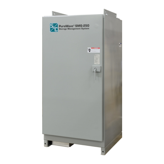
S&C PureWave® SMS-250 Storage Management System
Power Conversion System
263 kW/263 kVA, 380 V
Table of Contents
Section
Qualified Persons . . . . . . . . . . . . . . . . . . . . . . . . . . . . . . 2
Read this Instruction Sheet . . . . . . . . . . . . . . . . . . . . . . 2
Retain this Instruction Sheet . . . . . . . . . . . . . . . . . . . . . 2
Proper Application . . . . . . . . . . . . . . . . . . . . . . . . . . . . . . 2
Warranty . . . . . . . . . . . . . . . . . . . . . . . . . . . . . . . . . . . . . 2
Warranty Qualifications . . . . . . . . . . . . . . . . . . . . . . . . . . 2
Understanding Safety-Alert Messages . . . . . . . . . . . . . 3
Following Safety Instructions . . . . . . . . . . . . . . . . . . . . . 3
Replacement Instructions and Labels . . . . . . . . . . . . . . . 3
Location of Safety Labels . . . . . . . . . . . . . . . . . . . . . . . . 4
. . . . . . . . . . . . . . . . . . . . . . . . . . . . . 5
Enclosure . . . . . . . . . . . . . . . . . . . . . . . . . . . . . . . . . . . . 6
LCD Screen . . . . . . . . . . . . . . . . . . . . . . . . . . . . . . . . . . 6
Dead-Front Access Panels . . . . . . . . . . . . . . . . . . . . . . . 7
Inner Components . . . . . . . . . . . . . . . . . . . . . . . . . . . . . 7
User Interface . . . . . . . . . . . . . . . . . . . . . . . . . . . . . . . . . 8
Control Assembly . . . . . . . . . . . . . . . . . . . . . . . . . . . . . . 9
Inverter . . . . . . . . . . . . . . . . . . . . . . . . . . . . . . . . . . . . . . 9
October 3, 2016
© S&C Electric Company 2015-2016, all rights reserved
Operation and Maintenance
Page
Section
Ac and Dc Circuit Breakers . . . . . . . . . . . . . . . . . . . . . . 10
EMI Filters . . . . . . . . . . . . . . . . . . . . . . . . . . . . . . . . . . . 11
Cable Termination Area . . . . . . . . . . . . . . . . . . . . . . . . . 11
Fuses . . . . . . . . . . . . . . . . . . . . . . . . . . . . . . . . . . . . . . 12
Service Shelf . . . . . . . . . . . . . . . . . . . . . . . . . . . . . . . . 12
Radio Provisions . . . . . . . . . . . . . . . . . . . . . . . . . . . . . . 14
Human Machine Interface . . . . . . . . . . . . . . . . . . . . . . . 14
HMI Program . . . . . . . . . . . . . . . . . . . . . . . . . . . . . . . . . 15
System Design . . . . . . . . . . . . . . . . . . . . . . . . . . . . . . . 24
System Operation . . . . . . . . . . . . . . . . . . . . . . . . . . . . . 24
States . . . . . . . . . . . . . . . . . . . . . . . . . . . . . . . . . . . . . . 24
Resets . . . . . . . . . . . . . . . . . . . . . . . . . . . . . . . . . . . . . 25
Alarm Types . . . . . . . . . . . . . . . . . . . . . . . . . . . . . . . . . 25
Basic Operation . . . . . . . . . . . . . . . . . . . . . . . . . . . . . . 25
Alarm List and Troubleshooting Tips . . . . . . . . . . . . . . . 29
Annual Inspections . . . . . . . . . . . . . . . . . . . . . . . . . . . . 43
Maintenance Checklist . . . . . . . . . . . . . . . . . . . . . . . . . 43
Annual Maintenance Checklist . . . . . . . . . . . . . . . . . . . 43
. . . . . . . . . . . . . . . . . . . . . . . . . . . . . . . . 42
Instruction Sheet 659-520
Page
Advertisement
Table of Contents

Related Manuals for S&C PureWave SMS-250


Summary of Contents for S&C PureWave SMS-250
-
Page 1: Table Of Contents
S&C PureWave® SMS-250 Storage Management System Power Conversion System 263 kW/263 kVA, 380 V Operation and Maintenance Table of Contents Section Page Section Page Introduction Ac and Dc Circuit Breakers . . . . . . . . . . . . . . . . . . . . . . 10 Qualified Persons . -
Page 2: Introduction
The equipment in this publication must be selected for a specific application . The applica- tion must be within the ratings furnished for the equipment . Refer to S&C General Brochure 659-G358 for the S&C PureWave SMS-250 Storage Management System . Failure to do so may result in damage of the equipment . -
Page 3: Safety Information
Safety Information Understanding Several types of safety-alert messages may appear throughout this instruction sheet and on labels attached to the PureWave SMS-250 unit. Familiarize yourself with these types Safety-Alert of messages and the importance of these various signal words: Messages DANGER “DANGER”... -
Page 4: Location Of Safety Labels
Safety Information Location of Safety Labels Reorder Information for Safety Labels Location Safety Alert Message Description Part Number DANGER KEEP OUT . RISK OF ELECTRICAL SHOCK … PE-70479-1 NOTICE B★ REAR CLEARANCE … PE-70482-1 DANGER ARC FLASH AND SHOCK … PE-70483-1 ★... -
Page 5: Safety Precautions
Safety Precautions DANGER The PureWave SMS-250 system operates at hazardous voltage. Failure to observe the precautions below will result in serious personal injury or death. Some of these precautions may differ from your company’s operating procedures and rules . Where a discrepancy exists, follow your company’s operating procedures and rules . -
Page 6: Components And Controls
Components and Controls Enclosure The enclosure houses the PCS. The weatherproof, tamper-resistant NEMA 4 enclosure helps protect the system from environmental factors and unauthorized interference. Access to the system components shall be by means of a door at the front of the enclo- sure. -
Page 7: Dead-Front Access Panels
Components and Controls Dead-Front Access WARNING Panels Do not remove the dead-front access panels unless qualified to do so . Potentially lethal voltages are present beyond the dead-front access panels . High-voltage dc may be present even without the utility power connected . Upon opening the PCS enclosure door, the three dead-front access panels are shown. -
Page 8: User Interface
Components and Controls User Interface The PureWave SMS-250 can be controlled through the user interface located at the top left side of the unit. Figure 5 shows the controls available on the user interface. Figure 5. User interface. The controls on the user interface are as follows: −This switch enables the user to switch control from SCADA mode... -
Page 9: Control Assembly
Components and Controls Control Assembly The control assembly inputs and indicators are located on the front of the control assembly pull-out drawer located at the top-right side of the unit. See Figure 6. This assembly contains all the necessary DSP, microcontroller, application, and scale boards for operation. -
Page 10: Ac And Dc Circuit Breakers
Components and Controls Ac and Dc Circuit The PCS has two circuit breakers located in the lower-middle section of the unit. See Figure 8 for the location of the circuit breakers. The two circuit breakers are: Breakers −The ac circuit breaker can automatically isolate the PCS Ac Circuit Breaker (CB1) from the utility feeder in the event of a Trip Offline alarm. -
Page 11: Emi Filters
Components and Controls EMI Filters Located below the circuit breakers are ac and dc electromagnetic interference (EMI) filters. These filters are designed to prevent any IGBT interference by shunting the high frequency. See Figure 9 for the location of the EMI filters. EMI filters Figure 9. -
Page 12: Fuses
Components and Controls Fuses Six fuses are located to the left of the circuit breakers. See Figure 11. Some are rated differently from others because the ratings pertain to their application. Fuses Figure 11. Location of fuses. To replace a fuse, no hardware is necessary. Pulling the fuse latch forward will open the holder. - Page 13 Components and Controls Bolt the brackets in the location specified in Figure 13. STEP 2. Figure 13. Location of brackets installation. Place the shelf-top on top of the brackets and through the bolts as seen in STEP 3. Figure 14. Figure 14.
-
Page 14: Radio Provisions
Components and Controls Radio Provisions The PCS enclosure is supplied with provisions for radio communication. A removable panel to mount the radio and 24-Vdc power are located next to the LCD circuitry on the inside of the enclosure door. See Figure 16. Radio Provisions Figure 16. -
Page 15: Hmi Program
HMI Program The HMI program contains the following screens that, when selected, show the status of the PureWave SMS-250 system and its different components. The screens are as follows: PureWave SMS-250 System Oneline The PureWave SMS-250 System Oneline tab displays an overview of the PureWave SMS-250 system that includes the status of the island and ac and dc circuit breakers. - Page 16 Components and Controls Status The Status tab displays the alarm, analog, and digital status for the PureWave SMS-250 system. Figure 18 shows where the user can find these screens by placing the mouse over the Status tab to display the status drop-down menu items: Alarm Status, Analogs, and Digitals.
- Page 17 Components and Controls Figure 20. The Analog statuses window. Figure 21. The Digital statuses window. S&C Instruction Sheet 659-520...
- Page 18 Components and Controls Power Scheduling The Power Scheduling tab enables the user to charge and discharge the PureWave SMS-250 system at desired time durations and power levels during any time of the week. As seen in Figure 22, the user can place the mouse over the Power Scheduling tab to display the power scheduling drop-down menu items, Profile Setup and Week Setup.
- Page 19 Components and Controls Figure 24. The Week Schedule Setup window. Command and Control The Command and Control tab enables the user to command real or reactive power to the load. It also allows the user to choose different modes of operation, such as peak shaving, renewable smoothing, schedule follow, or islanding.
- Page 20 Components and Controls SCADA Test The SCADA Test tab enables the user to change SCADA inputs and outputs (analog and digital) for a desired time to verify that the SCADA system is functioning properly. As seen on Figure 26, the user can place the mouse over the SCADA Test tab to dis- play the SCADA test drop-down menu items, AI (Analog Inputs), AO (Analog Outputs), DI (Digital Inputs), and DO (Digital Outputs).
- Page 21 Components and Controls Figure 28. The Analog Outputs window. Figure 29. The Digital Inputs window. S&C Instruction Sheet 659-520...
- Page 22 Components and Controls Figure 30. The Digital Outputs widow. Configuration The Configuration tab enables the user to change communications and field settings. As seen in Figure 31, the user can place the mouse over the Configuration tab to dis- play the configuration Field Parameters and Communication drop-down menu items. Figures 32 and 33 (on page 23) show the screen of these menu items, respectively.
- Page 23 Components and Controls Figure 32. The Field Settings window. Figure 33. The Communication Setup window. S&C Instruction Sheet 659-520...
-
Page 24: Operation
(vars) States Listed in Table 2 are the five operating states of the PureWave SMS-250 system. Depend- ing on the alarm condition, the system can be in any of these states. The LCD inside the unit door and in Human Machine Interface (HMI) computer can both inform the user of the system's current state. -
Page 25: Resets
• SCADA: If the SCADA Trip Offline command is set, the user can clear the bit at DNP Point 0 (Trip Offline) to latch off the Trip Offline request for the PureWave SMS-250 system to go to the Ready state. - Page 26 • HMI: On the user interface, toggle the SMS CONTROL switch to the SCADA DISABLE setting. On the Command-Control HMI screen, choose the desired control mode and enter the power or vars value. This allows the PureWave SMS-250 system to go to the Utility Connected Run state.
- Page 27 (24 V) is removed, the PureWave SMS-250 will move to the Island mode. After the utility returns and is at a normal voltage and frequency for 300 seconds (configurable on the Configuration—...
- Page 28 Operation NOTICE The PureWave SMS-250 system open contact must be wired to open the island circuit breaker . The PureWave SMS-250 system close contact must be wired to close the island circuit breaker . The Islanding Breaker Feedback mode must be configured so there is voltage (24 Vdc) when the island circuit breaker is closed and the voltage (24 Vdc) is removed when it is open .
-
Page 29: Alarm List And Troubleshooting Tips
Island Run Ready (for Island Run Test Modes) The PureWave SMS-250 system automatically moves to the Ready state when the utility source has been restored. However, the storage-management system can also be manu- ally commanded to the Ready state as follows: •... - Page 30 Operation Information Status Alarms These notifications provide the status of the PureWave SMS-250 system and will not affect the proper operation of the system. See Table 5 for the listed information statuses. Table 5. PureWave SMS-250 Information Status Alarms Alarm...
- Page 31 Operation Table 5. PureWave SMS-250 Information Status Alarms—continued Alarm Description Reset Type Load Over Current Indicates the PureWave SMS-250 system cannot provide SELF enough current to island and support the load Troubleshooting Tip: No action is required. Load Over Power...
- Page 32 Operation Table 5. PureWave SMS-250 Information Status Alarms—continued Alarm Description Reset Type SOC Correction Indicates the PureWave SMS-250 system is conducting SOC SELF Active correction Troubleshooting Tip: No action is required. Synchronized to Indicates the PureWave SMS-250 system is synchronized to...
- Page 33 Troubleshooting Tip: Look at the data to see if the low voltage is on the island or the PureWave SMS-250 side. If it is on the island side, one at a time, check the island feedback fuses in the PCS enclosure. If the fuses are...
- Page 34 Operation Table 6. PureWave SMS-250 Warning Alarms—continued Alarm Description Reset Type Execution Time Indicates the software is running a loop that takes longer than SELF Long Warning the standard 208μs Troubleshooting Tip: Reset the alarm and contact S&C Electric Company.
- Page 35 Operation Table 6. PureWave SMS-250 Warning Alarms—continued Alarm Description Reset Type IGBT 3 Over Indicates IGBT 3 is too hot (This alarm is used to notify the SELF Temperature user while still continuing operation .) Troubleshooting Tip: Check the vents at the back of the Warning PCS enclosure to ensure there are no air restrictions.
- Page 36 Troubleshooting Tip: If the alarm is continuously active, the PureWave SMS-250 is seeing currents over 2PU (800 A for a single PureWave SMS-250). If this is not expected, contact S&C Electric Company.
- Page 37 Troubleshooting Tip: Contact a trained technician to troubleshoot the communication problem. Sensitive Earth Indicates the PureWave SMS-250 system three phase current MANUAL Fault does not sum to zero . Troubleshooting Tip: The alarm can be reset to bring the inverter back to an operating mode.
- Page 38 Operation Table 7. PureWave SMS-250 Inhibit Alarms—continued Alarm Description Reset Type Time Current Indicates the current is too high for too long, risking damage MANUAL Curve Overload to the IGBTs Troubleshooting Tip: Reduce island load. Under Frequency Indicates the line frequency at the ac connection is below the...
- Page 39 The system will operate on a limited basis when a Battery isolate condition is being displayed. The dc circuit breaker will open. See Table 8 for the listed Battery Isolate alarms. Table 8. PureWave SMS-250 Battery Isolate Alarms Alarm Description...
- Page 40 'Discharge Spring' message, the motor operator is not working. The breaker can still be closed by charging the spring by manually pulling down the charging handle several times. Reset the PureWave SMS-250 and determine whether the circuit breaker closes. Dc Link Shorted...
- Page 41 Operation Table 9. PureWave SMS-250 Trip Offline Alarms—continued Alarm Description Reset Type Execution Frame Indicates the software has a second loop that is executed MANUAL Overrun during the first loop, which can result in unexpected current Troubleshooting Tip: Reset the alarm and contact S&C Electric Company.
-
Page 42: Specifications
Specifications NOTICE The PureWave SMS-250 system is capable of servicing the distributed power genera- tion needs of its users when operated within its design limitations and specifications . Nonproprietary operation specifications for the PureWave SMS-250 system beyond those identified in this instruction sheet may be obtained from S&C Electric Company . -
Page 43: Maintenance
Maintenance Annual Inspections After the PureWave SMS-250 system is commissioned and the unit is online, inspection and maintenance should be scheduled for the PCS on an annual basis to ensure the proper operation of the system. Schedules for maintenance should be reviewed by the... - Page 44 (dc fuse). □ Disconnect the ac power that supplies the PureWave SMS-250 system. □ Lock open the ac power that supplies the PureWave SMS-250 system. □ Tag open the ac power that supplies the PureWave SMS-250 system. □ Disconnect the dc power that supplies the PureWave SMS-250 system.
- Page 45 Maintenance □ Verification • Verify there is no ac voltage from the door bond to the bottom of F1. • Verify there is no dc voltage from the door bond to the bottom of F1. • Verify there is no ac voltage from the door bond to the bottom of F2. •...
- Page 46 Maintenance □ Remove the three dead-front access panels from inside the PCS enclosure using a #2 Phillips driver for the screws at the top of each panel and a 13-mm socket wrench. See Figure 34. Figure 34. Dead-front access panel removal. Maintenance Inspection Enclosure □...
- Page 47 Maintenance Clean PCS Enclosure Fans □ Inductor fan (requires removal of inductor fan cover. See Figure 35.) 13 MM SOCKET - 9 N-M (7 FT-LBS) USE EXTENSION TO REACH 13 MM SOCKET 9 N-M (7 FT-LBS) Figure 35. Removal of inductor fan cover. □...
- Page 48 Maintenance Power electronic assemblies □ For IGBT inverter pole assembly servicing, install the service shelf in the PCS as illustrated in Figure 36. Figure 36. Shelf installation for pole(s) servicing. □ Remove the three IGBT inverter assemblies using the procedure located at the top inside of the PCS enclosure door.
- Page 49 Maintenance Table 12. Torque Requirements Torque Torque Assembly Part Hardware Tool [N-M] [Ft-Lbs] Inverter Pole Ground Wire M6 Hex Nut 11-mm Socket 9 .5 Ground Bus M6 Hex Nut 11-mm Socket 9 .5 Shorting Bus M10 Flange 15-mm Socket 54 .2 Typical Bus M10 Flange 15-mm Socket...
- Page 50 Verify all applicable maintenance tasks are complete. □ Verify all tools have been removed from the PCS enclosure. □ Visually inspect the PureWave SMS-250 to ensure nothing is out of place before re-energization. □ Replace and secure the dead-front access panels.
- Page 51 Maintenance Departure Place the PureWave SMS-250 system in the desired control mode and state. Record these below: Control Mode (SCADA - Enabled or Disabled): ____________________ System State: ____________________ □ Close and padlock all access doors. □ Send the CompactFlash card to S&C Electric Company for analysis.
Need help?
Do you have a question about the PureWave SMS-250 and is the answer not in the manual?
Questions and answers