S&C PureWave SMS-250 Installation Manual
Hide thumbs
Also See for PureWave SMS-250:
- Operation and maintenance (61 pages) ,
- Operation and maintenance (51 pages) ,
- Installation manual (16 pages)
Table of Contents
Advertisement
Quick Links
S&C PureWave
SMS-250 Storage Management System
®
263 kW/263 kVA, 380 V
Table of Contents
Section
Qualified Persons . . . . . . . . . . . . . . . . . . . . . . . . . . . . . . 2
Read this Instruction Sheet . . . . . . . . . . . . . . . . . . . . . . 2
Retain this Instruction Sheet . . . . . . . . . . . . . . . . . . . . . 2
Proper Application . . . . . . . . . . . . . . . . . . . . . . . . . . . . . 2
Warranty . . . . . . . . . . . . . . . . . . . . . . . . . . . . . . . . . . . . . 2
Warranty Qualifications . . . . . . . . . . . . . . . . . . . . . . . . . 2
Important Safety Instructions . . . . . . . . . . . . . . . . . . . . . 3
Understanding Safety-Alert Messages . . . . . . . . . . . . . 3
Following Safety Instructions . . . . . . . . . . . . . . . . . . . . . 3
Replacement Instructions and Labels . . . . . . . . . . . . . . 3
Location of Safety Labels . . . . . . . . . . . . . . . . . . . . . . . . 4
Trip Settings . . . . . . . . . . . . . . . . . . . . . . . . . . . . . . . . . . 5
Breaker Protection Curves . . . . . . . . . . . . . . . . . . . . . . . 6
. . . . . . . . . . . . . . . . . . . . . . . . . . . . 7
Packing . . . . . . . . . . . . . . . . . . . . . . . . . . . . . . . . . . . . . . 8
Inspection . . . . . . . . . . . . . . . . . . . . . . . . . . . . . . . . . . . . 9
Handling . . . . . . . . . . . . . . . . . . . . . . . . . . . . . . . . . . . . . 9
May 29, 2018
© S&C Electric Company 2017-2018, all rights reserved
Installation
Page
Section
System Design . . . . . . . . . . . . . . . . . . . . . . . . . . . . . . . 11
Concrete Pad Specifications . . . . . . . . . . . . . . . . . . . . 11
Pad Requirements . . . . . . . . . . . . . . . . . . . . . . . . . . . . 11
Mounting . . . . . . . . . . . . . . . . . . . . . . . . . . . . . . . . . . . . 12
Cable Terminations . . . . . . . . . . . . . . . . . . . . . . . . . . . 13
Battery Connection . . . . . . . . . . . . . . . . . . . . . . . . . . . . 13
Power Connections . . . . . . . . . . . . . . . . . . . . . . . . . . . 13
Wiring . . . . . . . . . . . . . . . . . . . . . . . . . . . . . . . . . . . . . . 13
Lugs for Battery and Power Connections . . . . . . . . . . 14
Metering Current Transformers . . . . . . . . . . . . . . . . . . 14
Earth Reference and Bonding . . . . . . . . . . . . . . . . . . . 14
Before Completing the Installation . . . . . . . . . . . . . . . . 16
Pre-Startup Checklist . . . . . . . . . . . . . . . . . . . . . . . . . . 16
Annual Inspections . . . . . . . . . . . . . . . . . . . . . . . . . . . . 16
Power Conversion System
Instruction Sheet 659-555
Page
Advertisement
Table of Contents

Related Manuals for S&C PureWave SMS-250


Summary of Contents for S&C PureWave SMS-250
-
Page 1: Table Of Contents
S&C PureWave SMS-250 Storage Management System Power Conversion System ® 263 kW/263 kVA, 380 V Installation Table of Contents Section Page Section Page Introduction Installation, Assembly, and Setup Qualified Persons . . . . . . . . . . . . . . . . . . . . . . . . . . . . . . 2 System Design . -
Page 2: Introduction
PROMISE INCLUDED IN PRICE SHEET 150. Warranty The seller’s warranties are contingent upon the installation and adjustment of the S&C PureWave SMS-250 Storage Management System in accordance with S&C’s applicable Qualifications instruction sheets, data sheets, and/or data bulletins. S&C Instruction Sheet 659-555... -
Page 3: Safety Information
Safety Information Important Safety SAVE THESE INSTRUCTIONS Instructions This manual contains important instructions for the PureWave® SMS-250 Storage Management System that shall be followed during installation and maintenance of the SMS-250. Understanding Several types of safety-alert messages may appear throughout this instruction sheet and on labels attached to the PCS. -
Page 4: Location Of Safety Labels
. The ac breaker disconnects the ac output to theload . A dc breaker to disconnect the PureWave SMS-250 from the battery is not included in the equipment and must be considered in the system design . -
Page 5: Trip Settings
Safety Information Trip Settings The PCS will trip under the conditions shown in Table 1. Table 1. Default Trip Settings Default Limits Adjustable Range Default Limits Nominal Value Trip Time (Sec.) Value Trip Time (Sec.) <0 .5 Vnom 380 V 190 V 0 . -
Page 6: Breaker Protection Curves
Safety Information Breaker Protection The power conversion system has a fixed output. The ac breaker is configured at the factory with the following protection curve: Curves Current in Amperes S&C Instruction Sheet 659-555... -
Page 7: Safety Precautions
Safety Precautions DANGER The PureWave SMS-250 Storage Management System operates at hazardous voltage. Failure to observe the precautions below will result in serious personal injury or death. Some of these precautions may differ from your company’s operating procedures and rules . Where a discrepancy exists, follow your company’s operating procedures and rules . -
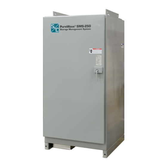
Page 8: Shipping And Handling
See Figures 1 and 2. NOTICE The Human Machine Interface (HMI) computer and bat- teries for the PureWave SMS-250 system are shipped separately . Figure 1. The power conversion system enclosure. Figure 2. Internal view of the power conversion system. -
Page 9: Inspection
NOTICE The PCS enclosure shall be lifted according to lifting drawing PEA-1610-4-IN and any other project-specific lifting drawings supplied with the PureWave SMS-250 system . Lifting equipment such as spreader bars and hoist sling straps are provided by others . - Page 10 Shipping and Handling To lift and place the PureWave SMS-250 PCS, follow these procedures: This point should be at least 45 inches (1143 mm) above STEP 1. If spreader bars are used for lifting, make sure the the top of the PCS enclosure .
-
Page 11: Installation, Assembly, And Setup
For specific applications that do not Pad Dimensions and Mounting Provisions require a battery pack, the PureWave SMS-250 assembly will be supplied without the dc EMI filter, and dc bus terminations. The concrete pad contractor is responsible for pad design and dimensions. -
Page 12: Shimming, Grouting, And Caulking The Pcs Enclosure
Installation, Assembly, and Setup Shimming, Grouting, and Caulking the PCS Enclosure To shim, grout, and caulk the PureWave SMS-250 PCS enclosure, follow these procedures: STEP 1. After placing the PCS enclosure at the desired location, check whether there are any gaps between the enclosure and the concrete pad. -
Page 13: Cable Terminations
Cable Terminations NOTICE For internal bus and cabling connections, refer to instal- lation drawing PEA-1610-4-IN and any project-specific drawings supplied with the PureWave SMS-250 system . See Figure 6 for the location of the cable-termination area . Battery Connection STEP 7. The battery must be supplied with an adequate protection fuse and a disconnect breaker. -
Page 14: Lugs For Battery And Power Connections
SMS-250 unit uses power converters that switch at frequencies up to 5 kHz. For S&C PureWave SMS-250 equipment and systems rated less than 1000 kVA, the resistance of the PureWave SMS-250 earth reference connection to earth is... -
Page 15: Communications Signal Reference Requirements
“point-to-point” check on all of the wiring to verify the system is wired, labeled, and terminated per drawing PEA-1610-4-IN and any project- specific drawings supplied with the PureWave SMS-250 system. Note any problems found and corrective actions applied. -
Page 16: Inspection Recommendations
S&C Electric Company at (414) 423-8766. Annual Inspections After the PureWave SMS-250 system is commissioned and the unit is online, inspection and maintenance should be scheduled for the PCS on an annual basis to ensure the proper operation of the system.
Need help?
Do you have a question about the PureWave SMS-250 and is the answer not in the manual?
Questions and answers