Table of Contents
Advertisement
Quick Links
NC8J Series
User's Manual
NO. G03-NC8J-F
Revision: 2.0
Release date: October 30, 2020
Trademark:
* Specifications and Information contained in this documentation are furnished for information use only, and are
subject to change at any time without notice, and should not be construed as a commitment by manufacturer.
Advertisement
Table of Contents

Related Manuals for JETWAY NC8J Series


Summary of Contents for JETWAY NC8J Series
- Page 1 NC8J Series User’s Manual NO. G03-NC8J-F Revision: 2.0 Release date: October 30, 2020 Trademark: * Specifications and Information contained in this documentation are furnished for information use only, and are subject to change at any time without notice, and should not be construed as a commitment by manufacturer.
- Page 2 Environmental Protection Announcement Do not dispose this electronic device into the trash while discarding. To minimize pollution and ensure environment protection of mother earth, please recycle.
-
Page 3: Table Of Contents
TABLE OF CONTENT ENVIRONMENTAL SAFETY INSTRUCTION................iii USER’S NOTICE..........................iv MANUAL REVISION INFORMATION...................iv ITEM CHECKLIST..........................iv CHAPTER 1 INTRODUCTION OF THE MOTHERBOARD FEATURE OF MOTHERBOARD..................1 SPECIFICATION........................2 LAYOUT DIAGRAM.......................3 CHAPTER 2 HARDWARE INSTALLATION JUMPER SETTING........................ 8 CONNECTORS AND HEADERS..................15 2-2-1 CONNECTORS......................15 2-2-2 HEADERS........................ -
Page 4: Environmental Safety Instruction
Environmental Safety Instruction Avoid the dusty, humidity and temperature extremes. Do not place the product in any area where it may become wet. 0 to 40 centigrade is the suitable temperature. (The temperature comes from the request of the chassis and thermal solution) ... -
Page 5: User's Notice
USER’S NOTICE COPYRIGHT OF THIS MANUAL BELONGS TO THE MANUFACTURER. NO PART OF THIS MANUAL, INCLUDING THE PRODUCTS AND SOFTWARE DESCRIBED IN IT MAY BE REPRODUCED, TRANSMITTED OR TRANSLATED INTO ANY LANGUAGE IN ANY FORM OR BY ANY MEANS WITHOUT WRITTEN PERMISSION OF THE MANUFACTURER. -
Page 6: Chapter 1 Introduction Of The Motherboard
Chapter 1 Introduction of the Motherboard 1-1 Feature of Motherboard Onboard Intel ® Apollo Lake Series Processor, with low power consumption and high performance Support 1* DDR3L 1866MHz SO-DIMM, maximum capacity up to 8GB Integrated with Realtek Gigabit Ethernet LAN chip ... -
Page 7: Specification
1-2 Specification Spec Description Design Mini-ITX form factor 6 layers; PCB size: 17.0x17.0cm Intel ® Apollo Lake series CPU(Default J3455, CO-LAY N3350) * for detailed CPU support information please visit our website 1*DDR3L SO-DIMM slot support DDR3L 1866 MHz SO-DIMM up to 8GB Memory Slot * Note: Memory clock supporting range is decided by specific CPU of the model. -
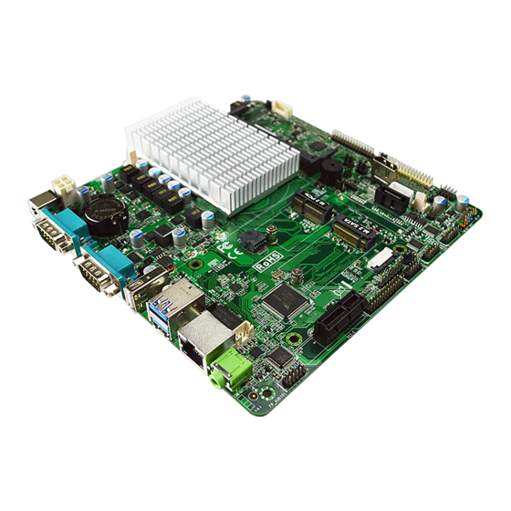
Page 8: Layout Diagram
Internal I/O Connectors & Headers: 1* 4-pin internal 12V power connector 1* SATA Power-out connector 1* CPUFAN connector & 1* SYSFAN connector 1* Internal vertical HDMI port 1* Front panel header 2* 9-Pin USB 2.0 header for 4* USB 2.0/1.1 ports ... - Page 9 Motherboard Internal Diagram: Internal 12V DC-IN CPUFAN Power Jack 12V DC-IN Power Jack INVERTER COM1 Serial Port DDR3L SODIMM Slot COM2 Serial Port LVDS Header USB 2.0 Port M.2 E-Key Slot (M2E) SMBUS USB 3.0 Ports EDP1 Header Internal HDMI Port Speaker SATA SATAIII...
- Page 10 Motherboard Jumper Position: JPCOM1 JBAT JPCOM2 JAT_ATX1 JPCOM3...
- Page 11 Connectors Connector Name DCIN1 12V DC-In Power Jack COM1/COM2 RS232 Serial Port Connector USB 2.0 Port Connector USB31 USB 3.0 Port Connector x2 LAN1 RJ-45 LAN Connector LINE-OUT Line-out Connector DCIN3 4-Pin Internal 12V Power Connector SATA SATAIII Connector SATAPWR SATA Power Out Connector SYSFAN System FAN Connector...
- Page 12 EDP1 EDP Header 29-pin Block 2.0mm Jumper Jumper Name Description Pitch JPCOM1 COM1 Port Pin9 Function Select 4-pin Block 2.0mm JPCOM2 COM2 Port Pin9 Function Select 4-pin Block 2.0mm JPCOM3 COM3 Header Pin9 Function Select 4-pin Block 2.0mm JBAT Clear CMOS RAM & Clear ME_RTC 4-pin Block 2.0mm USB31 Port VCC Select...
-
Page 13: Chapter 2 Hardware Installation
Chapter 2 Hardware Installation 2-1 Jumper Setting JPCOM1 (4-pin): COM1 Port Pin9 Function Select JPCOM1 JPCOM1 COM1 Port Pin-9 → 2 4 6 2 4 6 1 3 5 2-4 Closed: 3-4 Closed: 4-6 Closed: RI=RS232 RI= 5V; RI= 12V. (Default);... - Page 14 JPCOM3 (4-pin): COM3 Header Pin-9 Function Select JPCOM3 COM3 Header Pin-9 → 2 4 6 2 4 6 1 3 5 2-4 Closed: 3-4 Closed: 4-6 Closed: JPCOM3 RI=RS232 RI= 5V; RI= 12V. (Default); JBAT (4-pin): Clear CMOS RAM Settings & Clear ME_RTC JBAT Clear CMOS &...
- Page 15 JP9 (3-pin): USB31 Port VCC Select → USB31 Port VCC Select USB31 1-2 Closed: USB31 Ports= 5VSB; 2-3 Closed: USB31 Ports= VCC. JAT_ATX1 (3-pin): ATX Mode/ AT Mode Select JAT_ATX1 → ATX/AT M ode Select JAT_ATX1 1-2 Closed: ATX Mode Selected; 2-3 Closed: AT Mode Selected.
- Page 16 JP1 (3-pin): M2E Slot VCC Select → M 2E Slot Power VCC Select 1-2 Closed: M2E Slot Power = VCC3; 2-3 Closed: M2E Slot Power = 3VSB. Pin (1-2) of JP2 (4-pin): Case Open Message Display Function Select Pin(1-2) of JP2 →...
- Page 17 Pin (3-4) of JP2 (4-pin):TXE Override Pin(3-4) of JP2 → TXE Override Pin1 3-4 Open: Normal; Pin1 3-4 Close: TXE Override JP3 (4-pin): LVDS LCD Panel VCC Select...
- Page 18 JP4 (3-pin): LVDS Inverter Backlight VCC Select → LVDS Inverter VCC Select 1-2 Closed: Inverter Baklight= 5V; 2-3 Closed: Inverter Baklight= 12V. JP6 (3-pin): EDP1 Backlight Power VCC Select → EDP1 Backlight VCC Select 1-2 Closed: EDP1 Backlight VCC=5V; 2-3 Closed: EDP1 Backlight VCC=12V.
- Page 19 JP7 (4-pin): EDP LCD Power VCC Select...
-
Page 20: Connectors And Headers
Connectors and Headers 2-2-1 Connectors (1) Rear Panel Connectors *refer to Page-3. Icon Name Function 12V DC-In system power connector. 12V DCIN For user to connect compatible power adapter to Power Connector provide power supply for the system. Mainly for user to connect external MODEM or other Serial Port devices that supports Serial Communications Interface. - Page 21 (2) COM1/COM2(9-pin): RS232 Serial Port Connector 1 2 3 4 5 Pin1 6 7 8 9 (3) DCIN3 (4-pin): Internal 12V Power Connector Pin1 Pin No. Definition +12V +12V...
- Page 22 (4) SATA (7-pin): SATAIII Port connector SATA port is a high-speed SATAIII port that supports 6GB/s transfer rate. SATA (5) SATAPWR(4-pin): SATA HDD Power-Out Connector +12V SATAPWR Pin1 Warning: Make sure that Pin-1 of compatible SATA Power out connector is inserted into corresponding Pin-1 of SATAPWR connector to avoid possible damage to the board and hard disk driver !
- Page 23 (6) SYSFAN (3-pin):System Fan Connector Pin1 +12V Fan Power Fan Speed SYSFAN (7) CPUFAN (3-pin): CPU Fan Connector CPUFAN Pin1...
-
Page 24: Headers
2-2-2 Headers (1) JW_FP (9-pin,Pitch=2.54mm): Front Panel Header JW_FP (2) FP_USB1/FP_USB2(9-pin,Pitch=2.0mm): USB 2.0 Port Header F_USB2 F_USB1... - Page 25 (3) COM3/COM4 (9-pin,Pitch=2.0mm): Serial Port Header COM3:RS232/422/485 Serial Port Header;COM4:RS232 Serial Port Header Pin NO. RS232 *RS422 *RS485 (optional) (optional) Pin 1 DATA- Pin 2 DATA+ Pin 3 Pin 4 Pin 5 Pin 6 Pin 7 Pin 8 COM4 *COM3 Pin 9 Pin 1 *Note: COM3 header can function as RS232/422/485 port header.
- Page 26 (5) LPT (25-pin,Pitch=2.0mm): Parallel Port Header Pin2 Pin1 Pin NO. Pin Definition Pin NO. Pin Definition Pin 1 STB- Pin 2 AFD- Pin 3 Pin 4 ERR- Pin 5 Pin 6 INIT- Pin 7 Pin 8 SLIN- Pin 9 Pin 10 Pin 11 Pin 12 Pin 13...
- Page 27 (6) GPIO(10-Pin,Pitch=2.0mm): GPIO Port Header Pin1 GPIO (7) SMBUS (5-Pin,Pitch=2.0mm): SMBUS Header Pin1 SMBUS_CLK SMBUS_DATA SMBUS_ALERT- SMBUS SMBUS_DATA 3VSB...
- Page 28 (8) FP_AUDIO1 (9-pin,Pitch=2.0mm): Line-Out, MIC-In Header This header connects to Front Panel Line-out, MIC-In connector with cable. FP_AUDIO1 (9) SPEAK_CON (4-pin block, Pitch=2.0mm): 3W Amplifier Wafer SPEAK_CON...
- Page 29 (10) PS2_CON(6-pin Pitch=2.54mm): PS/2 Keyboard & Mouse Port Header PS2_CON (11) INVERTER1 (6-pin,Pitch=2.0mm): LVDS Inverter Pin1 INVERTER1 Pin No. Definition BKLT_PWR1 BKLT_PWR2 BKLT_EN BKLT_PWM BKLT_GND1 BKLT_GND2 Warning! Find Pin-1 location of the inverter and make sure that the installation direction is correct! Otherwise serious harm will occur to the board/display panel!!
- Page 30 (12) LVDS (30-pin,Pitch=2.0mm): 24-bit Dual Channel LVDS Header LVDS Pin NO. Pin Define Pin NO. Pin Define Pin 1 LCD_VCC Pin 2 LCD_VCC Pin 3 LCD_VCC Pin 4 Pin 5 Pin 6 Pin 7 LVDSA_DATAN0 Pin 8 LVDSA_DATAP0 Pin 9 LVDSA_DATAN1 Pin 10 LVDSA_DATAP1...
- Page 31 (13) EDP1 (29-pin,Pitch=2.0mm): EDP Header EDP1 Pin NO. Pin Define Pin NO. Pin Define Pin 1 BKLT_PW Pin 2 BKLT_PW Pin 3 BKLT_PW Pin 4 Pin 5 EDP1_DEC Pin 6 Pin 7 No Key Pin 8 Pin 9 EDP_VCC Pin 10 Pin 11 EDP_VCC Pin 12...
-
Page 32: Chapter 3 Introducing Bios
Chapter 3 Introducing BIOS Notice! The BIOS options in this manual are for reference only. Different configurations may lead to difference in BIOS screen and BIOS screens in manuals are usually the first BIOS version when the board is released and may be different from your purchased motherboard. Users are welcome to download the latest BIOS version form our official website. -
Page 33: Bios Menu Screen
BIOS Boot Menu Screen (boot device options please refer to actual configuration) BIOS Menu Screen The following diagram show a general BIOS menu screen: Menu Bar General Help Items Current Setting Value Menu Items Function Keys... -
Page 34: Function Keys
Function Keys In the above BIOS Setup main menu of, you can see several options. We will explain these options step by step in the following pages of this chapter, but let us first see a short description of the function keys you may use here: ... -
Page 35: Menu Bars
3-5 Menu Bars There are six menu bars on top of BIOS screen: Main To change system basic configuration Advanced To change system advanced configuration Chipset To change chipset configuration Security Password settings Boot To change boot settings Save & Exit Save setting, loading and exit options. -
Page 36: Advanced Menu
System Date Set the date. Please use [Tab] to switch between date elements. System Time Set the time. Please use [Tab] to switch between time elements. 3-7 Advanced Menu OS Selection The optional settings: [Windows]; [Intel Linux]; [MSDOS]. * Note: User need to go to this item to select the OS mode before installing corresponding OS driver, otherwise problems will occur when installing the driver. - Page 37 The optional settings: [Disabled]; [Enabled]. When set as [Enabled], user can make further settings in the following items: SHA-1 PCR Bank Use this item to enable or disable SHA-1 PCR Bank. The optional settings: [Disabled]; [Enabled]. SHA256 PCR Bank Use this item to enable or disable SHA256 PCR Bank. The optional settings: [Disabled];...
- Page 38 Press [Enter] to make settings for the following sub-items: When set as [Enabled], user can make further settings in the following items: Device Settings Serial Port Use this item to enable or disable Serial Port 2 (COMB). The optional settings: [Disabled]; [Enabled]. When set as [Enabled], user can make further settings in the following items: Change Settings Use this item to select an optimal setting for Super IO Device.
- Page 39 Use this item to enable or disable Serial Port 4 (COMD). The optional settings: [Disabled]; [Enabled]. When set as [Enabled], user can make further settings in the following items: Device Settings Change Settings Use this item to select an optimal setting for Super IO Device. The optional settings: [Auto];...
- Page 40 The optional settings: [Disabled]; [Enabled]. This item should be set as [Disabled] if you wish to have all active wake-up functions. Case Open Detect Use this item to detect if case have ever been opened. Show message in POST. The optional settings: [Disabled]; [Enabled]. When set as [Enabled], system will detect if COPEN has been short or not (refer to JP2 jumper setting for Case Open Detection);...
- Page 41 ATX Power Emulate AT Power This item support Emulate AT power function, MB power On/Off control by power supply. Use needs to select ‘AT or ATX Mode’ on MB jumper at first (refer to JAT_ATX1 jumper setting for ATX Mode & AT Mode Select). ...
- Page 42 [Even]: parity bit is 0 if the num of 1’s in the data bits is even; [Odd]: parity bit is 0 if num of 1’s in the data bits is odd; [Mark]: parity bit is always 1; [Space]: parity bit is always 0; [Mark] and [Space]: parity do not allow for error detection.
- Page 43 Redirect After BIOS POST The optional settings: [Always Enable]; [BootLoader]. When [Bootloader] is selected, then Legacy Console Redirection is disabled before booting to legacy OS. When [Always Enabled] is selected, then Legacy Console Redirection is enabled for legacy OS. Default setting for this option is set to [Always Enabled].
- Page 44 Hardware flow control uses two wires to send start/stop signals. The optional settings: [None]; [Hardware RTS/CTS]; [Software Xon/Xoff]. Data Bits The default setting is: [8]. *This item may or may not show up, depending on different configuration. Parity The default setting is: [None]. *This item may or may not show up, depending on different configuration.
- Page 45 will switch to minimum speed when all cores enter C-State. Max Package C State This item is for user to control the Max Package C State that the processor will support. The optional items are: [PC2]; [PC1]; [C0]. Max Core C States This option controls the Max Core C State that cores will support.
- Page 46 This item controls Legacy/UEFI ROMs priority. The optional settings: [UEFI and Legacy]; [Legacy Only]; [UEFI Only]. Network This item controls the execution of UEFI and Legacy PXE OpROM. The optional settings: [Do not Launch]; [UEFI]; [Legacy]. Storage This item controls the execution of UEFI and Legacy Storage OpROM. The optional settings: [Do not Launch];...
- Page 47 minute(s). USB Wake-up from S4 Use this item to enable or disable USB S4 Wake-up. The optional settings: [Enabled]; [Disabled]. *Note: This function is supported when ‘ERP Support’ is set as [Disabled]. USB Configuration Press [Enter] to make settings for the following sub-items: USB Configuration USB Devices Legacy USB Support...
-
Page 48: Chipset Menu
itself to the Host Controller. ‘Auto’ uses default value: for a root port it is 100 ms, for a Hub port the delay is taken from Hub descriptor. The optional settings: [Auto]; [Manual]. Select [Manual] you can set value for the following sub-item: ‘Device power-up Delay in Seconds’, the delay range in from 1 to 40 seconds, in one second increments. - Page 49 used by the Internal Graphics Device. The optional settings: [64M]; [96M]; [128M]; [160M]; [192M]; [224M]; [256M]; [288M]; [320M]; [352M]; [384M]; [416M]; [448M]; [480M]; [512M]. DVMT Total Gfx Mem Use this item to select DVMT 5.0 Total Graphics Memory size used by the Internal Graphics Device.
- Page 50 Secondary IGFX Boot Display Use this item to select Secondary Display Device. The optional settings: [Disabled]; [HDMI]; [eDP]; [LVDS]. Memory Information The working memory information will be on display. South Cluster Configuration ► PCI Express Configuration Press [Enter] to make settings for the following sub-items: PCI Express Configuration Peer Memory Write Enable The optional settings: [Disabled];...
- Page 51 Use this item to enable or disable SATA port. The optional settings: [Disabled]; [Enabled]. HD-Audio Support Use this item to enable or disable HD-Audio Support. The optional settings: [Disabled]; [Enabled]. SCC eMMC Support Use this item to enable or disable SCC eMMC Support. The optional settings: [Disabled];...
-
Page 52: Security Menu
3-9 Security Menu Security menu allow users to change administrator password and user password settings. Administrator Password If there is no password present on system, please press [Enter] to create new administrator password. If password is present on system, please press [Enter] to verify old password then to clear/change password. - Page 53 The optional settings: [Disabled]; [Enabled]. Secure Boot can be enabled if 1. System running in user mode with enrolled Platform Key (PK); 2. CSM function is disabled. Secure Boot Mode The optional settings: [Standard]; [Custom]. Set UEFI Secure Boot Mode to Standard mode or Custom mode. This change is effective after save.
-
Page 54: Boot Menu
Key: Vendor, Custom, Mixed, Test (*) modified from Setup menu 3-10 Boot Menu Setup Prompt Timeout Use this item to set number of seconds to wait for setup activation key. 65535(0xFFFF) means indefinite waiting. Bootup NumLock State Use this item to select the keyboard NumLock state. The optional settings: [On];... -
Page 55: Save & Exit Menu
Boot Option #2 Use this item to set the system boot order. The optional settings: [MMC - Biwin]; [UEI: Built-in EFI Shell]; [Disabled]. Hard Drive BBS Priorities Use this item to set the order of the legacy devices in this group. Press [Enter] to make customized secure settings: Boot Option#1 The optional settings: [MMC - Biwin];... - Page 56 Restore Defaults Use this item to restore /load default values for all the setup options. Save as User Defaults Use this item to save the changes done so far as user defaults. Restore User Defaults Use this item to restore defaults to all the setup options. Boot Override The available options here are dynamically updated and make system boot to any boot option selected.
Need help?
Do you have a question about the NC8J Series and is the answer not in the manual?
Questions and answers