Table of Contents
Advertisement
Quick Links
Technical Manual
Of
Intel Braswell Series CPU
Based Mini-ITX M/B
NO.G03-NF591-F
Revision: 2.0
Release date: October 1, 2019
Trademark:
* Specifications and Information contained in this documentation are furnished for information use only, and are
subject to change at any time without notice, and should not be construed as a commitment by manufacturer.
Advertisement
Table of Contents

Related Manuals for JETWAY NF591


Summary of Contents for JETWAY NF591
- Page 1 Technical Manual Intel Braswell Series CPU Based Mini-ITX M/B NO.G03-NF591-F Revision: 2.0 Release date: October 1, 2019 Trademark: * Specifications and Information contained in this documentation are furnished for information use only, and are subject to change at any time without notice, and should not be construed as a commitment by manufacturer.
- Page 2 Environmental Protection Announcement Do not dispose this electronic device into the trash while discarding. To minimize pollution and ensure environment protection of mother earth, please recycle.
-
Page 3: Table Of Contents
TABLE OF CONTENT ENVIRONMENTAL SAFETY INSTRUCTION ................iv USER’S NOTICE ........................v MANUAL REVISION INFORMATION ..................v ITEM CHECKLIST ........................v CHAPTER 1 INTRODUCTION OF THE MOTHERBOARD FEATURE OF MOTHERBOARD ................1 SPECIFICATION ......................2 LAYOUT DIAGRAM ....................3 CHAPTER 2 HARDWARE INSTALLATION JUMPER SETTING ..................... -
Page 4: Environmental Safety Instruction
Environmental Safety Instruction Avoid the dusty, humidity and temperature extremes. Do not place the product in any area where it may become wet. 0 to 60 centigrade is the suitable temperature. (The figure comes from the request of the main chipset) ... -
Page 5: User's Notice
USER’S NOTICE COPYRIGHT OF THIS MANUAL BELONGS TO THE MANUFACTURER. NO PART OF THIS MANUAL, INCLUDING THE PRODUCTS AND SOFTWARE DESCRIBED IN IT MAY BE REPRODUCED, TRANSMITTED OR TRANSLATED INTO ANY LANGUAGE IN ANY FORM OR BY ANY MEANS WITHOUT WRITTEN PERMISSION OF THE MANUFACTURER. -
Page 6: Chapter 1 Introduction Of The Motherboard Feature Of Motherboard
Chapter 1 Introduction of the Motherboard Feature of Motherboard ® Onboard Intel Braswell series SoC Processor, with low power consumption never denies high performance Support 2* DDR3L 1600 MHz SO-DIMM, up to 8GB Onboard 2 * RJ-45 gigabit Ethernet LAN port ... -
Page 7: Specification
Specification Spec Description 6 layers; PCB size: 17x 17 cm Design ® Intel Braswell *SoC CPU *CPU model varies from different IPC options. Please consult your Embedded CPU dealer for more information of onboard CPU. 2 * DDR3L SODIMM Slot for un-buffered *DDR3L 1600 MHz SDRAM, expandable to 8GB Memory Slot ... -
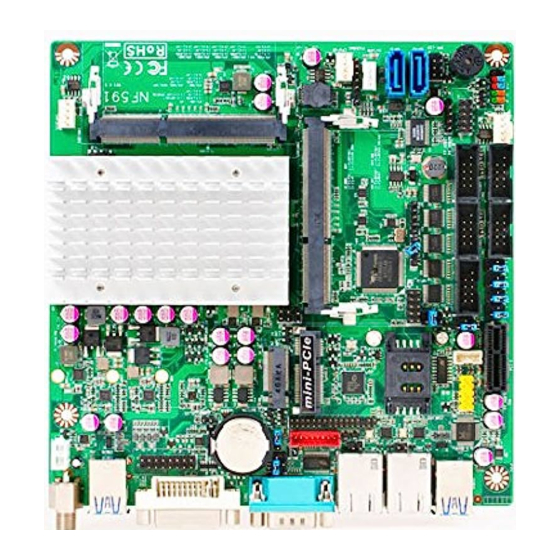
Page 8: Layout Diagram
1* 4-pin USB 2.0 header (Expansible to 1* USB 2.0 port) 1* 9-pin USB 2.0 header (Expansible to 2* USB 2.0 ports) 1* Front panel header 1* Power LED & speaker header 1* PS/2 keyboard & mouse header ... - Page 9 Motherboard Internal Diagram Internal 12V DC-in SYSFAN1 Header Power connector 12V DC -in Power Connector Intel CPU USB 3.0 Ports VGA Port Header *DDR3L SODIMM Slot (SODIMM1) M Key-2242/2260/2280 DVI-D Port Connector (*M2) Full-size Mini-PCIE Slot (MPE) *DDR3L SODIMM Slot (SODIMM2) COM1 Serial Port...
- Page 10 Jumper Position: RTC_RST JBAT COPEN AT_MODE...
- Page 11 Jumper Jumper Name Description COM1 Port Pin9 Function Select 4-Pin Block COM2 Header Pin9 Function Select 4-Pin Block COM3 Header Pin9 Function Select 4-Pin Block COM4 Header Pin9 Function Select 4-Pin Block COM5 Header Pin9 Function Select 4-Pin Block COM6 Header Pin9 Function Select 4-Pin Block LVDS Panel VCC 3.3V /5V/12V Select 4-Pin Block...
- Page 12 Headers Header Name Description FP_AUDIO Front Panel Audio Header 9-pin Block SPEAK_CON Speaker Header 4-pin Block LAN1_LED/LAN2LED LAN Activity LED Header 2-pin Block FP_USB21 USB 2.0 Header 4-pin Block FP_USB20 USB 2.0 Header 9-pin Block JW_FP Front Panel Header(PWR LED/ 9-pin Block HDD LED/Power Button /Reset) SPK-LED...
-
Page 13: Chapter 2 Hardware Installation
Chapter 2 Hardware Installation 2-1 Jumper Setting JP1 (4-pin): COM1 Port Pin9 Function Select → COM1 Port Pin-9 2 4 6 2 4 6 1 3 5 1 3 5 2-4 Closed: 3-4 Closed: 4-6 Closed: RI=RS232(Default); RI= 5V; RI= 12V. JP3 (4-pin): COM2 Header Pin9 Function Select →... - Page 14 JP6 (4-pin): COM3 Header Pin9 Function Select → COM3 Header Pin-9 2-4 Closed: 3-4 Closed: 4-6 Closed: RI=RS232; RI= +5V; RI= +12V. JP7 (4-pin): COM4 Header Pin9 Function Select → COM4 Header Pin-9 2-4 Closed: 3-4 Closed: 4-6 Closed: RI=RS232; RI= +5V;...
- Page 15 JP8 (4-pin): COM5 Header Pin9 Function Select → COM5 Header Pin-9 2-4 Closed: 3-4 Closed: 4-6 Closed: RI=RS232; RI= +5V; RI= +12V. JP9 (4-pin): COM6 Header Pin9 Function Select → COM6 Header Pin-9 2-4 Closed: 3-4 Closed: 4-6 Closed: RI=RS232; RI= +5V;...
- Page 16 JP5 (4-pin): LVDS Panel VCC 3.3V/5V/12V Select → LVDS Panel VCC 2-4 Closed: 3-4 Closed: 4-6 Closed: VCC= 5V VCC= 12V. VCC=3.3V; (Default); JP4 (3-pin): INVERTER Back Light VCC 5V/12V Select → INVERTER Back Light VCC 1-2 Close: INVERTER Back Light 5V Selected; 2-3 Close: INVERTER Back Light 12V Selected(Default).
- Page 17 COPEN (2-pin): Case Open Message Display Function Select COPEN 1-2 Open: Normal(Defualt); 1-2 Closed: Case Open Function Selected(One Touch). Pin 1-2 Close: When Case open function pin short to GND, the Case open function was detected. When Used, needs to enter BIOS and enable ‘Case Open Detect’ function.
- Page 18 *ATX Mode Selected: Press power button to power on after power input ready; AT Mode Selected: Directly power on as power input ready. RTC_RST (2-pin): Reset All RTC Register Bits RTC_RST 1-2 Open: Normal(Default); 1-2 Close: RTC Reset. Pin 1 & 2 of JBAT (6-pin): Flash Descriptor Security Override →...
- Page 19 Pin 3 & 4 of JBAT (6-pin): Clear CMOS Setting → Pin 3-4 of JBAT Clear CMOS Pin1 3-4 Open: Normal(Default); Pin1 3-4 Closed: Clear CMOS(One Touch). Pin 5&6 of JBAT (6-pin): ODD Present Select → Pin 5-6 of JBAT ODD Present Select Pin1 5-6 Open: Normal (Default);...
-
Page 20: Connectors And Headers
Connectors and Headers 2-2-1 Connectors (1) Rear I/O Connectors COM1 USB 3.0 Ports Serial Port DVI-D Port DC-in 12V Power Connector USB 3.0 Ports RJ-45 LAN Ports Icon Name Function For user to connect compatible power 12V DC-in Power adapter to provide power supply for the Connector system. - Page 21 (2) COM1 (9-pin Block): RS232/422/485 Port COM1 port can function as RS232/422/485 port. In normal settings COM1 functions as RS232 port. With compatible COM cable COM1 can function as RS422 or RS 485 port. User also needs to go to BIOS to set ‘Transmission Mode Select’ for COM1 (refer to Page 31) at first, before using specialized cable to connect different pins of this port.
- Page 22 (4) SATA1/SATA2(7-pin Block): SATAIII Port connector These are high-speed SATAIII ports that support 6GB/s transfer rate. Pin No. Definition (5) SATAPW (4-pin): SATA Power Out Connector Warning: Make sure that Pin-1 of compatible SATA Power connector is inserted into corresponding Pin-1 of PWOUT to avoid possible damage to the board and hard disk driver!
-
Page 23: Headers
(6) CPUFAN1/SYSFAN1/SYSFAN2 Connector (4-pin): FAN Connectors 2-2-2 Headers (1) FP_AUDIO (9-pin): Line-Out, MIC-In Header This header connects to Front Panel Line-out, MIC-In connector with cable. Pin 1 Line-Out, MIC Header... - Page 24 (2) SPEAK_CON (4-pin): Speaker Connector Pin No. Definition (3) LAN1_LED/LAN2_LED (2-pin): LAN Activity LED Header LED- LED+ Pin 1...
- Page 25 (4) FP_USB21 (4-pin): USB 2.0 Port Header Pin 1 (5) FP_USB20 (9-pin): USB 2.0 Port Header Pin 1...
- Page 26 (6) JW_FP (9-pin): Front Panel Header Pin 1 (7) SPK-LED (7-pin): Speaker Header & PWR LED Header Pin 1...
- Page 27 (8) PS2KBMS (6-pin): PS2 Keyboard & Mouse Header Pin1 (9) SMBUS (5-Pin): SM BUS Header Pin1...
- Page 28 (10) GPIO_CON (10-pin): GPIO Header Pin1 (11) COM2/3/4/5 (9-pin): Serial Port Header Pin6 Pin1...
- Page 29 (12) LVDS (30-pin): 24-bit Dual Channel LVDS Header Pin2 Pin 1 Pin NO. Pin Define Pin NO. Pin Define Pin 1 LVDSB_DATAN3 Pin 2 LVDSB_DATAP3 Pin 3 LVDS_CLKBN Pin 4 LVDS_CLKBP Pin 5 LVDSB_DATAN2 Pin 6 LVDSB_DATAP2 Pin 7 LVDSB_DATAN1 Pin 8 LVDSB_DATAP1 Pin 9...
- Page 30 (13) INVERTER (8-pin): LVDS Inverter Connector Pin No. Definition Backlight Enable Backlight PWM Backlight VCC Pin1 Backlight VCC Backlight Brightness Up SW Backlight Brightness Down SW Warning! Find Pin-1 location of the inverter and make sure that the installation direction is correct! Otherwise serious harm will occur to the board/display panel!! (14) FP_VGA(15-pin): VGA Port Header...
-
Page 31: Chapter 3 Introducing Bios
Chapter 3 Introducing BIOS Notice! The BIOS options in this manual are for reference only. Different configurations may lead to difference in BIOS screen and BIOS screens in manuals are usually the first BIOS version when the board is released and may be different from your purchased motherboard. Users are welcome to download the latest BIOS version form our official website. -
Page 32: Bios Menu Screen
BIOS Menu Screen The following diagram show a general BIOS menu screen: Menu Bar General Help Items Menu Items Current Setting Value Function Keys Function Keys In the above BIOS Setup main menu of, you can see several options. We will explain these options step by step in the following pages of this chapter, but let us first see a short description of the function keys you may use here: ... -
Page 33: Getting Help
Press <+>/<–> keys when you want to modify the BIOS parameters for the active option. [F1]: General help. [F2]: Previous value. [F3]: Optimized defaults. [F4]: Save & Exit. [F7]: To enter pop-up boot menu to select boot device. ... -
Page 34: Main Menu
Main Menu Main menu screen includes some basic system information. Highlight the item and then use the <+> or <-> and numerical keyboard keys to select the value you want in each item. System Date Set the date. Please use [Tab] to switch between data elements. System Time Set the time. -
Page 35: Advanced Menu
3-7 Advanced Menu Trusted Computing Press [Enter] to enable or disable Security Device Support. TPM20 Device Found Security Device Support Use this item to enable or disable BIOS support for security device. TCG EFI protocol and INT1A interface will not be available. The optional settings: [Disabled];... - Page 36 ACPI Settings Press [Enter] to make settings for the following sub-item: ACPI Settings ACPI Sleep State Use this item to select the highest ACPI sleep state the system will enter when the suspend button is pressed. The optional settings are: [Suspend Disabled]; [S3 (Suspend to RAM)]. ...
- Page 37 Use this item to select an optimal setting for super IO device. Serial Port FIF0 Mode The optional settings are: [16-Byte FIF0]; [32-Byte FIF0]; [64-Byte FIF0]; [128-Byte FIF0]. OS Select for Serial Port The optional settings: [Windows]; [LINUX]. ERP Support The optional settings: [Disabled];...
- Page 38 This item displays current Emulate AT Power Status, motherboard power On/Off control by power supply. User needs to select ‘AT or ATX Mode’ on MB jumper at first (refer to Page 9, Pin (1&2) of J1 for ATX Mode & AT Mode Select). ...
- Page 39 Recorder Mode The optional settings are: [Disabled]; [Enabled]. Resolution 100x31 The optional settings are:[Disabled]; [Enabled]. Legacy OS Redirection Resolution The optional settings are: [80x24]; [80x25]. Putty Keypad The optional settings are: [VT100]; [LINUX]; [XTERMR6]; [SCO]; [ESCN]; [VT400]. Redirection After BIOS POST The optional settings are: [Always Enable];...
- Page 40 Data Bits The default setting is: [8]. *This item may or may not show up, depending on different configuration. Parity The default setting is: [None]. *This item may or may not show up, depending on different configuration. Stop Bits The default setting is: [1]. *This item may or may not show up, depending on different configuration.
- Page 41 Use this item to select system shutdown temperature. The optional settings are: [Disabled]; [65 C/148 F]; [70 C/156 F]; [75 C/164 C/172 F]; [85 C/180 CPU Configuration Press [Enter] to view current CPU configuration and make settings for the following sub-items: Limit CPUID Maximum The optional settings: [Disabled];...
- Page 42 SATA Interface Speed The item is for user to set the maximum speed the SATA controller can support. The optional settings are: [Gen1]; [Gen2]; [Gen3]. SATA Port1/ SATA Port2 Port1/ Port2 The optional settings are: [Enabled]; [Disabled]. Network Stack Configuration Press [Enter] to go to ‘Network Stack’...
- Page 43 This item controls the execution of UEFI and legacy PXE OpROM. The optional settings are: [Do not launch]; [UEFI only]; [Legacy]. Storage This item controls the execution of UEFI and Legacy Storage OpROM. The optional settings are: [Do not launch]; [UEFI only]; [Legacy]. Other PCI devices This item determines OpROM execution policy for devices other than Network, storage or video.
- Page 44 [Disabled]: To keep USB devices available only for EFI specification, [Auto]: To disable legacy support if no USB devices are connected. XHCI Hand-off This is a workaround for OSes without XHCI hand-off support. The XHCI ownership change should be claimed by XHCI driver. The optional settings are: [Enabled];...
-
Page 45: Chipset Menu
TPM Configuration fTPM The optional settings are: [Enabled]; [Disabled]. IntelRMT Configuration Press [Enter] to make settings for the following sub-item: IntelRMT Configuration Intel RMT Support The optional settings are: [Enabled]; [Disabled]. When set as [Enabled], user can make further settings in the following item: HW Notification The optional settings are: [Disabled];... - Page 46 North Bridge Press [Enter] to view memory configurations or make settings for the following sub-items: PAVC Use this item to enable or disable protected audio video control. The optional settings are: [Disabled]; [Enabled]. DVMT Pre-Allocated Use this item to select DVMT 5.0 pre-allocated (fixed) graphics memory size used by the internal graphics device.
- Page 47 The optional setting are: [800x 480 1ch 18-bit]; [800x 600 1ch18-bit]; [800x 600 1ch 24-bit]; [1024 x 600 1ch 18-bit]; [1024 x 768 1ch 18-bit]; [1024 x 768 1ch 24-bit]; [1280 x 768 1ch 24-bit]; [1280 x 800 1ch 18-bit]; [1280 x 800 1ch 24-bit]; [1366 x 768 1ch 18-bit];...
-
Page 48: Security Menu
The optional settings are: [Always Off]; [Always On]; [Former State]. * The option [Always On] and [Former State] are affected by ERP function. Please disable ERP to support [Always On] and [Former State] function. 3-9 Security Menu Security menu allow users to change administrator password and user password settings. -
Page 49: Boot Menu
3-10 Boot Menu Boot Configuration Setup Prompt Timeout Use this item to set number of seconds to wait for setup activation key. Bootup Numlock State Use this item to select keyboard numlock state. The optional settings are: [On]; [Off]. Quiet Boot The optional settings are: [Disabled];... -
Page 50: Save & Exit Menu
New Boot Option Policy This item controls the placement of newly detected UEFI boot options. The optional settings are: [Default]; [Place First]; [Place Last]. 3-11 Save & Exit Menu Save Changes and Reset This item allows user to reset the system after saving the changes. Discard Changes and Reset This item allows user to reset the system without saving any changes. - Page 51 Use this item to save the changes done so far as user defaults. Restore User Defaults Use this item to restore the user defaults to all the setup options. Boot Override Boot Override UEFI:xx/… Press this item to select the device as boot disk after save configuration and reset. Launch EFI Shell from filesystem device This item is used for attempts to launch EFI shell application from one of the available file system devices.
Need help?
Do you have a question about the NF591 and is the answer not in the manual?
Questions and answers