Table of Contents
Advertisement
Quick Links
TECHNICAL MANUAL
Of
Intel H110 Express Chipset
Based Mini-ITX M/B
NO. G03-NC5D-F
Revision: 1.0
Release date: November 28, 2016
Trademark:
* Specifications and Information contained in this documentation are furnished for information use only, and are
subject to change at any time without notice, and should not be construed as a commitment by manufacturer.
Advertisement
Table of Contents

Related Manuals for JETWAY NC5D-IH110-950


Summary of Contents for JETWAY NC5D-IH110-950
- Page 1 TECHNICAL MANUAL Intel H110 Express Chipset Based Mini-ITX M/B NO. G03-NC5D-F Revision: 1.0 Release date: November 28, 2016 Trademark: * Specifications and Information contained in this documentation are furnished for information use only, and are subject to change at any time without notice, and should not be construed as a commitment by manufacturer.
- Page 2 Environmental Protection Announcement Do not dispose this electronic device into the trash while discarding. To minimize pollution and ensure environment protection of mother earth, please recycle.
-
Page 3: Table Of Contents
TABLE OF CONTENT ENVIRONMENTAL SAFETY INSTRUCTION..............iii USER’S NOTICE ......................iv MANUAL REVISION INFORMATION ................iv ITEM CHECKLIST ......................iv CHAPTER 1 INTRODUCTION OF THE MOTHERBOARD FEATURE OF MOTHERBOARD ................1 SPECIFICATION ....................2 LAYOUT DIAGRAM ....................3 CHAPTER 2 HARDWARE INSTALLATION JUMPER SETTING.................... -
Page 4: Environmental Safety Instruction
Environmental Safety Instruction Avoid the dusty, humidity and temperature extremes. Do not place the product in any area where it may become wet. 0 to 40 centigrade is the suitable temperature. (The temperature comes from the request of the chassis and thermal solution) ... -
Page 5: User's Notice
USER’S NOTICE COPYRIGHT OF THIS MANUAL BELONGS TO THE MANUFACTURER. NO PART OF THIS MANUAL, INCLUDING THE PRODUCTS AND SOFTWARE DESCRIBED IN IT MAY BE REPRODUCED, TRANSMITTED OR TRANSLATED INTO ANY LANGUAGE IN ANY FORM OR BY ANY MEANS WITHOUT WRITTEN PERMISSION OF THE MANUFACTURER. -
Page 6: Chapter 1 Introduction Of The Motherboard Feature Of Motherboard
Chapter 1 Introduction of the Motherboard Feature of Motherboard ® Intel H110 express chipset ® ® Support LGA 1151 CPU socket Intel Core™ i7 processors / Intel Core™ i5 ® ® ® processors / Intel Core™ i3 processors / Intel Pentium™... -
Page 7: Specification
1-2 Specification Spec Description Design 6-Layer PCB; Size: 18.0 x 22.0cm Intel H110 Express Chipset Chipset ® ® Support Intel LGA 1151 Socket Core™ i7 processors, Intel ® ® Core™ i5 processors, Intel Core™ i3 processors, Intel CPU Socket ®... -
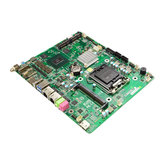
Page 8: Layout Diagram
Internal I/O Connectors& Headers: 1 *4-pin SATA HDD power-out connector 5* FAN connector 1*Front panel audio header 1* HDMI_SPDIF out header 1* SPEAK_CON header 1*Front panel header 1 * 4-Pin USB 2.0 header for 1* USB 2.0/1.1 port ... - Page 9 Motherboard Internal Diagram-Front Serial Port Headers (COM1/COM2) 19V DC-in Power Connector HDMI Port GPUFAN2 Header (HDMI1) HDMI Port HDMI Port *Full-size (HDMI2) Mini-PCIE Slot Header (MPE) *Full-size Mini-PCIE/MSATA Slot PS/2 Keyboard & Mouse (MINIPCIE/MSATA) Display Port Header Intel H110 Chipset USB 2.0 Port GPUFAN1 USB 2.0 Port Header...
- Page 10 Motherboard Internal Diagram--Back SIM Card Slot Note: SIM card slot only work when compatible SIM card installed & 3G LAN card installed in MPE1 Mini-PCIE slot.
- Page 11 Motherboard Jumper Position AT_MODE COPEN1 JBAT...
- Page 12 Connectors Connector Name DC19V_IN1 19V DC-in Power Connector HDMI1/2/4 HDMI Port Connector x3 Display Port Connector USB1 USB 2.0 Port Connector USB3_1 USB 3.0 Port Connector x2 LAN1/2 RJ-45 LAN Connector x2 LINE_OUT Audio Line-Out Connector Audio MIC Connector SATA1/2 SATAIII Connector x2 PWROUT1 SATA HDD Power-out Connector...
-
Page 13: Chapter 2 Hardware Installation
USB3_2 USB 3.0 Port Header 19-pin Block Jumper Jumper Name Description AT_MODE ATX Mode / AT Mode Select 2-pin Block MPE Slot Power VCC 3.3V/3.3VSB Select 3-pin Block ME_Features Select 2-pin Block JBAT Clear CMOS RAM Settings 2-pin Block COPEN1 Case Open Message Display Function 2-pin Block Chapter 2... - Page 14 JP2 (3-pin): MPE Slot VCC 3.3V/3.3 VSB Select → MPE Slot VCC 1-2 Closed: MPE Slot VCC= 3.3V; 2-3 Closed: MPE Slot VCC= 3.3VSB. JP1 (2-pin): ME Features Select → ME Features Select 1-2 Open: Enable ME Features; 1-2 Closed: Disable ME Features.
- Page 15 JBAT (2-pin): Clear CMOS RAM Settings → JBAT Clear CMOS 1-2 Open: Normal (Default); 1-2 Closed:Clear CMOS Settings. COPEN1 (2-pin):Case Open Message Display Function Select → COPEN1 Case Open Detect 1-2 Open: Normal (Default); 1-2 Close: Case Open Detect Function Selected(One Touch).
-
Page 16: Connectors And Headers
Connectors and Headers 2-2-1 Connectors (1) Rear Panel Connectors * For I/O diagram please refer to page-3. Icon Name Function For user to connect compatible power adapter to 19V DC-in Power provide power supply for the system. Jack Connector To connect display device that support HDMI HDMI Port specification. - Page 17 (2) SATA1/SATA2 (7-pin): SATA III Port connector SATA1&SATA2 are high-speed SATAIII port that supports 6 GB/s transfer rate. Pin No. Definition (3) PWROUT1(4-pin): SATA HDD Power-out Connector Pin1 Pin No. Definition +12V...
- Page 18 (4) CPUFAN1/GPUFAN1/GPUFAN2(4-pin):Fan Connector Pin1 Control +12V Fan Power Fan Speed Fan Speed +12V Fan Power Control Pin1 Pin1 GPUFAN2 GPUFAN1 CPUFAN (5) SYSFAN1/CHAFAN1(3-pin):Fan Connector Pin1 Pin1 +12V Fan Power Fan Speed CHAFAN1 SYSFAN1...
-
Page 19: Headers
2-2-2 Headers (1) FP_AUDIO (9-pin): Line-Out, MIC-In Header This header connects to Front Panel Line-out, MIC-In connector with cable. Pin 1 MIC2_L MIC2_R DETECT MIC_JD LINE_OUT_R SENSE LINE_OUT_JD LINE_OUT_L (2) HDMI_SPDIF(2-pin): HDMI-SPDIF Out header Pin1... - Page 20 (3) SPEAK_CON1 (4-pin block): Speaker Header Pin1 (4) JW_FP1 (9-pin): Front Panel Header Pin 1 HDD LED+ PWR LED+ HDD LED PWR LED - PWRBTN RSTSW...
- Page 21 (5) GPIO1(10-pin): GPIO Header Pin 1 GPIO_31 GPIO_30 GPIO_32 GPIO_33 GPIO_35 GPIO_34 GPIO_37 GPIO_36 (6) PS2_CON1 (6-pin): PS/2 Keyboard & Mouse Header Pin 1 KB_DATA KB_CLK MS_CLK MS_DATA...
- Page 22 (7) COM1/COM2 (9-Pin): RS232 Serial Port Header Pin6 Pin1 (8) HDMI3(20-Pin): HDMI Port Header Pin 1 HDMI_TXP2 HDMI_TXP1 HDMI_TXN2 HDMI_TXN1 HDMI_TXP0 HDMI_TXCP HDMI_TXN0 HDMI_TXCN HDMI_SDA HDMI_SCL HDMI_+5V HDMI_HPD...
- Page 23 (9) FP_ USB1(9-pin): USB 2.0 Port Header Pin 1 -DATA -DATA +DATA +DATA (10) FP_ USB2(9-pin): USB 2.0 Port Header Pin1 -DATA +DATA...
- Page 24 (11) USB3_2 (19-Pin): USB 3.0 Port Header Pin 1 D2 - GND2 GND1 SSTX2+ SSTX1+ SSTX2- SSTX1- GND3 GND0 SSRX2+ SSRX1+ SSRX2- SSRX1- VBUS2 VBUS...
-
Page 25: Chapter 3 Introducing Bios
Chapter 3 Introducing BIOS Notice! The BIOS options in this manual are for reference only. Different configurations may lead to difference in BIOS screen and BIOS screens in manuals are usually the first BIOS version when the board is released and may be different from your purchased motherboard. Users are welcome to download the latest BIOS version form our official website. -
Page 26: Bios Menu Screen
BIOS Menu Screen The following diagram show a general BIOS menu screen: Menu Bar General Help Items Function Keys Menu Items Current Setting Value BIOS Menu Screen Function Keys In the above BIOS Setup main menu of, you can see several options. We will explain these options step by step in the following pages of this chapter, but let us first see a short description of the function keys you may use here: ... -
Page 27: Getting Help
Press (up, down) to choose, in the main menu, the option you want to confirm or to modify. Press <Enter> to select. Press <+>/<–> keys when you want to modify the BIOS parameters for the active option. -
Page 28: Main Menu
User can press the right or left arrow key on the keyboard to switch from menu bar. The selected one is highlighted. Main Menu Main menu screen includes some basic system information. Highlight the item and then use the <+> or <-> and numerical keyboard keys to select the value you want in each item. -
Page 29: Advanced Menu
3-7 Advanced Menu ► ACPI Settings Press [Enter] to make settings for the following sub-items: ACPI Settings Enable Hibernation The optional settings: [Enabled]; [Disabled]. Use this item to enable or disable system ability to hibernate (OS/S4 Sleep State). This option may not be effective with some OS. ACPI Sleep State Use this item to select the highest ACPI sleep state the system will enter when the suspend button is pressed. - Page 30 The optional settings are: [Suspend Disabled]; [S3 (Suspend to RAM)]. ERP Support The optional settings: [Disabled]; [Enabled]. Use this item to enable or disable ERP function for this board. This item should be set as [Disabled] if you wish to have active all Wake-up functions.
- Page 31 Image Re-Flash’ as [Enabled], save the settings and exit. The system will turn off and reboot after 4 seconds. If the user goes to BIOS screen again will find this item is set again as [Disabled], but user can still re-flash to update firmware next time. ►...
- Page 32 ► H/W Monitor Press [Enter] to view current hardware health status, make further settings in ‘CPUFAN Smart Mode’ and ‘GPUFAN1 Smart Mode’. CPUFAN Smart Mode/GPUFAN1 Smart Mode The optional settings are: [Disabled]; [Enabled]. When set as [Enabled], the following sub-items shall appear: CPUFAN / GPUFAN1 Full-Speed Temperature Use this item to set CPUFAN/GPUFAN1 full speed temperature.
- Page 33 CPU C states Use this item to enable or disable CPU C states. The optional settings: [Disabled]; [Enabled]. When set as [Enabled], user can make further settings in ‘Package C State limit’. Package C State Limit The optional settings are: [C0/C1]; [C2]; [C3]; [C6]; [C7]; [C7s]; [C8]; [AUTO]. ►...
- Page 34 Hot Plug The optional settings: [Disabled]; [Enabled]. Use this item to designate this port as Hot Pluggable. MSATA1 Port2 The optional settings: [Disabled]; [Enabled]. Use this item to enable or disable device connected to mSATA. ► Network Stack Configuration Press [Enter] to go to ‘Network Stack’ screen to make further settings. Network Stack Use this item to enable or disable UEFI Network Stack.
- Page 35 The optional settings are: [UEFI and Legacy]; [Legacy only]; [UEFI only]. Storage This option controls the execution of UEFI and Legacy Storage OpROM. The optional settings are: [Do not launch]; [UEFI]; [Legacy]. Video Use this item to control the execution of UEFI and Legacy video OpROM. The optional settings are: [Do not launch];...
-
Page 36: Chipset Menu
Device power-up delay Use this item to set maximum time the device will take before it properly reports itself to the host controller. ‘Auto’ uses default value: for a root port it is 100 ms, for a hub port the delay is taken from hub descriptor. The optional settings: [Auto]; [Manual].Select [Manual] you can set value for the following sub-item: Device Power-up delay in seconds, the delay range in from 1 to 40 seconds, in one second increments. - Page 37 Use this item to enable or disable VT-d capability. The optional settings are: [Enabled]; [Disabled]. Above 4GB MMIO BIOS assignment Use this item to enable or disable above 4GB memory Mapped IO BIOS assignment. This item is disabled automatically when Aperture Size is set as 2048 The optional settings are: [Enabled];...
-
Page 38: Security Menu
Use this item to enable or disable high precision timer. The optional settings are: [Disabled]; [Enabled]. 3-9 Security Menu Security menu allow users to change administrator password and user password settings. Administrator Password Press [Enter] to create new administrator password. Press again to confirm the new administrator password. -
Page 39: Boot Menu
3-10 Boot Menu Setup Prompt Timeout Use this item to set number of seconds to wait for setup activation key. Bootup Numlock State Use this item to select keyboard numlock state. The optional settings are: [On]; [Off]. Boot Option Priorities Fast Boot Use this item to enable or disable boot with initialization of a minimal set of devices required to launch active boot option. - Page 40 When set as [Enabled], user can make settings in the following items that appear: SATA Support The optional settings are: [Last Boot HDD Only]; [All SATA Devices]. VGA Support The optional settings are: [Auto]; [EFI Driver]. *When set as [Auto], it will only install Legacy OpROM with Legacy OS and logo will not be shown during POST.
-
Page 41: Save & Exit Menu
3-11 Save & Exit Menu Save Changes and Reset This item allows user to reset the system after saving the changes. Discard Changes and Reset This item allows user to reset the system without saving any changes. Restore Defaults Use this item to restore /load default values for all the setup options. Save as User Defaults Use this item to save the changes done so far as user defaults. - Page 42 Boot Override UEFI:xx/… Press this item to select the device as boot disk after save configuration and reset Launch EFI Shell from filesystem device Press this item to launch EFI Shell application (Shell.efi) from one of the available file system device.
Need help?
Do you have a question about the NC5D-IH110-950 and is the answer not in the manual?
Questions and answers