Table of Contents
Advertisement
Quick Links
Advertisement
Table of Contents

Related Manuals for JETWAY NC9L


Summary of Contents for JETWAY NC9L
- Page 1 NC9L User Manual Rev: 1.0 Release date: Dec 17, 2019 Trademark: * Specifications and Information contained in this documentation are furnished for information use only, and are subject to change at any time without notice, and should not be construed as a commitment by manufacturer.
-
Page 2: Table Of Contents
TABLE OF CONTENT ENVIRONMENTAL SAFETY INSTRUCTION................iii ENVIRONMENTAL PROTECTION ANNOUCEMENT .............. iii USER’S NOTICE ........................iv MANUAL REVISION INFORMATION ..................iv ITEM CHECKLIST ........................iv CHAPTER 1 INTRODUCTION OF THE MOTHERBOARD SPECIFICATION ......................1 LAYOUT DIAGRAM ..................... 2 CHAPTER 2 HARDWARE INSTALLATION JUMPER SETTING ..................... -
Page 3: Environmental Safety Instruction
Environmental Safety Instruction Avoid the dusty, humidity and temperature extremes. Do not place the product in any area where it may become wet. 0 to 40 centigrade is the suitable temperature. (The figure comes from the request of the main chipset) ... -
Page 4: User's Notice
USER’S NOTICE COPYRIGHT OF THIS MANUAL BELONGS TO THE MANUFACTURER. NO PART OF THIS MANUAL, INCLUDING THE PRODUCTS AND SOFTWARE DESCRIBED IN IT MAY BE REPRODUCED, TRANSMITTED OR TRANSLATED INTO ANY LANGUAGE IN ANY FORM OR BY ANY MEANS WITHOUT WRITTEN PERMISSION OF THE MANUFACTURER. -
Page 5: Chapter 1 Introduction Of The Motherboard
Chapter 1 Introduction of the Motherboard 1-1 Specification Spec Description Design ATX form factor; PCB size: 30.5 x22 cm Intel ® H110 Express Chipset Chipset Core™ i7, Core™ i5, Core™ i3 series, Supports Intel ® CPU Socket ®... -
Page 6: Layout Diagram
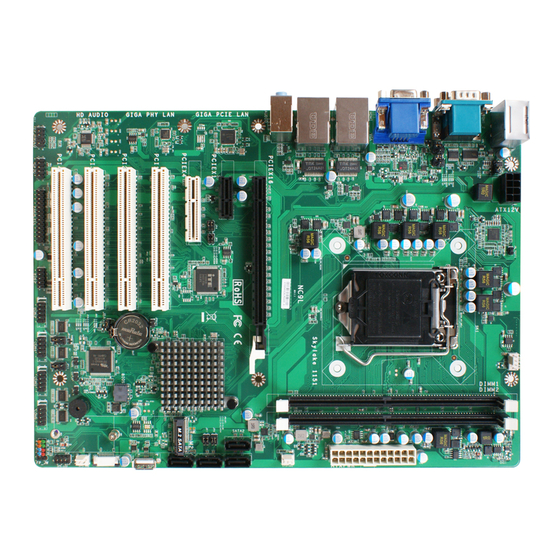
1* Front panel header 1* Speaker header+ 1* POWER LED header 3* FAN header 1* Vertical type connector USB 2.0 port 1-2 Layout Diagram Rear IO Diagram RJ-45 LAN Ports PS/2 Combo VGA Port Line-IN Line-OUT MIC-IN USB 2.0 Ports HDMI Port... - Page 7 Motherboard Internal Diagram ATX 12V Power Connector CPUFAN Header PS/2 over USB 2.0 Ports Serial Ports DDR4 (COM1/COM2) DIMM Slot x 2 VGA Port LGA 1151 over HDMI Port CPU Socket ATX Power Connector RJ-45 LAN Ports Over USB 3.0 Ports SYSFAN1 Header Audio Jack PCI Express 3.0 x 16 Slot...
- Page 8 Motherboard Jumper Position AT-mode JBAT COPEN JP10 JP11 Jumper Location Description PS/2-USB USB2.0 Port Function Select 3-pin Block (2.54 pitch) COM2 Port Pin9 Function Select 4-pin Block (2.54 pitch) COM1 Port Pin9 Function Select 4-pin Block (2.54 pitch) PCIEX1 & PCIEX4 Function Select 6-pin Block (2.54 pitch) PCIEX1 &...
- Page 9 Connectors Connector Description ATXPWR ATX Main Power Connector ATX12V ATX 12V Power Connector PS/2-USB Top: PS/2 combo Middle & Bottom: USB 2.0 Port Connector X2 COM1_2 Serial Port COM Connector X2 VGA Port Connector HDMI HDMI Port Connector UL1/UL2 Top: RJ-45 LAN Connector X2 Middle &...
-
Page 10: Chapter 2 Hardware Installation
Chapter 2 Hardware Installation 2-1 Jumper Setting JP1 (3-pin): PS/2-USB USB2.0 Port Function Select (2.54 pitch) JP2 (4-pin): COM2 Port Pin9 Function Select (2.54 pitch) JP2→COM2 Port Pin9 Function Select 2-4 Closed: 3-4 Closed: 4-6 Closed: RI=RS232 RI= 5V RI= 12V... - Page 11 JP3 (4-pin): COM1 Port Pin9 Function Select (2.54 pitch) JP4/5 (6-pin): PCIEX1 & PCIEX4 Function Select (2.54 pitch) 2 4 6 PCIEX1 Disable PCIEX4 Enable 1 3 5 JP4: JP5: 4-6 Closed 4-6 Closed 3-5 Closed 3-5 Closed ** JP4 Jumper setting Location must be the same of JP5. PCIEX1 &...
- Page 12 JP6/7 (6-pin): M.2 & SATA4 Port Function Select (2.54 pitch) JP6/7→M.2 & SATA4 Port Function Select ** 2 4 6 M.2 M-key Enable SATA4 Disable 1 3 5 JP6: JP7: 2-4 Closed 2-4 Closed 1-3 Closed 1-3 Closed JP8 (2-pin): ME Features Select (2.54 pitch) →...
- Page 13 JP10 (4-pin): COM3 Header Pin9 Function Select (2.54 pitch) JP11 (4-pin): COM4 Header Pin9 Function Select (2.54 pitch) JP11→COM4 Header Pin9 Function Select 2-4 Closed: 3-4 Closed: 4-6 Closed: RI=RS232 RI= 5V RI= 12V...
- Page 14 AT-MODE (2-pin): AT & ATX Mode Switch (2.54 pitch) → AT-MODE (2-pin) AT & ATX Mode Switch Pin 1 1-2 Open: ATX Mode Selected(Default) Pin 1 1-2 Closed: AT Mode Selected **ATX Mode Selected: Press power button to power on after power input ready; AT Mode Selected: Directly power on as power input ready.
- Page 15 JBAT (3-pin): Clear CMOS RAM Function Settings (2.54 pitch)
-
Page 16: Connectors And Headers
Connectors and Headers 2-2-1 Rear I/O Back Panel Connectors *Refer to Page-2. Icon Name Function Mainly for user to connect external MODEM or other devices that supports Serial Port Serial Communications Interface. **Note: COM1 supports RS232/422/485 function. To connect display device that support HDMI specification. -
Page 17: Motherboard Internal Connectors
2-2-2 Motherboard Internal Connectors (1) ATXPWR (24-pin block): Main Power Connector ATX Power Supply connector: This is a new defined 24-pins connector that usually comes with ATX case. The ATX Power Supply allows using soft power on momentary switch that connect from the front panel switch to 2-pins Power On jumper pole on the motherboard. - Page 18 (2) ATX12V (8-pin block): 12V Power Connector This is a new defined 8-pin connector that usually comes with ATX Power Supply that supports extra 12V voltage to maintain system power consumption. Without this connector might cause system unstable because the power supply can not provide sufficient current for system.
- Page 19 (4) M2: M-key Connector This M2 M-key connector support compatible type 2242/2280 SATA SSD module. M.2 Module Installation Guide 1. Prepare compatible M.2 SATA SSD 2242 or 2280 type card. Deferent type of cards has different length. Find corresponding nut location for further installation. (Ex.
-
Page 20: Header Pin Definition
2-2-3 Header Pin Definition (1) FP_AUDIO (9-pin): Front Panel Audio Header (2.54 pitch) This header is connected to Front Panel Line-out, MIC connector with cable. (2) GPIO (10-pin): GPIO Header (2.54 pitch) P i n 1... - Page 21 (3) PARALLEL (25-pin): Parallel Header (2.54 pitch) Pin NO. Pin Definition Pin NO. Pin Definition STB- AFD- Pin 1 Pin 14 PRD0 ERR- Pin 2 Pin 15 PRD1 INIT- Pin 3 Pin 16 PRD2 SLIN- Pin 4 Pin 17 PRD3 Pin 5 Pin 18 PRD4...
- Page 22 (4) USB1 (9-pin): USB 2.0 Header (2.54 pitch) (5) COM 3/4/5/6 (9-pin): Serial Port Header (2.54 pitch)
- Page 23 (6) JW_FP (9-pin): PWR LED/ HD LED/ Power Button /Reset (2.54 pitch) (7) SPK_LED (7-pin): PWR LED Header & Speaker Header Pin 1 PWR LED+ SPEAK+ VSB_LED PWR LED- SPEAK-...
- Page 24 (8) SYSFAN1/CPUFAN/SYSFAN2 (4-pin): FAN Headers (9) Dual Channel Memory Installation config Slot 1 Slot 2 install install install install Notice! For dual channel installation, you need to install the same brand, speed, size and type memory module. It is unable to activate dual channel feature if you install only one memory module. Slot order can be from left-to-right or right-to-left, and it must be installed in pairs.
-
Page 25: Chapter 3 Introducing Bios
Chapter 3 Introducing BIOS Notice! The BIOS options in this manual are for reference only. Different configurations may lead to difference in BIOS screen and BIOS screens in manuals are usually the first BIOS version when the board is released and may be different from your purchased motherboard. Users are welcome to download the latest BIOS version form our official website. -
Page 26: Bios Menu Screen
BIOS Menu Screen The following diagram show a general BIOS menu screen: Menu Bar General Help Items Current Setting Value Menu Items Function Keys Function Keys In the above BIOS Setup main menu of, you can see several options. We will explain these options step by step in the following pages of this chapter, but let us first see a short description of the function keys you may use here: ... -
Page 27: Getting Help
Getting Help Main Menu The on-line description of the highlighted setup function is displayed at the top right corner the screen. Status Page Setup Menu/Option Page Setup Menu Press [F1] to pop up a small help window that describes the appropriate keys to use and the possible selections for the highlighted item. -
Page 28: Advanced Menu
3-7 Advanced Menu CPU Configuration Press [Enter] to view current CPU configuration and make settings for the following sub-items: Hardware Prefetcher Use this item to turn on/off the MLC streamer prefecher. The optional settings: [Disabled]; [Enabled]. Adjacent Cache Line Prefetch Use this item to turn on/off prefeching of adjacent cache lines. - Page 29 Package C State Limit Use this item to select the maximum Package C State limit setting. The optional settings are: [C0/C1]; [C2]; [C3]; [C6]; [C7]; [C7S]; [C8]; [C9]; [C10]; [CPU Default]; [Auto]. [CPU Default]: Leaves to factory default value. [Auto]: Initializes to deepest available Package C State Limit. ...
- Page 30 When set as [Enabled], system will wake on the hour/min/sec specified. Wake-up System with Dynamic Time Use this item to enable or disable system wake on alarm event. System will wake on the current time + Increase minutes. The optional settings: [Disabled]; [Enabled]. When set as [Enabled], system will wake on the current time + increased minute(s).
- Page 31 Press [Enter] to make parameters of Parallel Port (LTP/LPTE) settings. Serial Port Use this item to enable or disable Serial Port (COM). The optional settings: [Disabled]; [Enabled]. *When set as [Enabled], user can make further settings in the following items: Change Settings Use this item to select an optimal setting for super IO device.
- Page 32 The optional settings: [Keyboard First]; [Mouse First]. PC Health Status Press [Enter] to view current hardware health status, set shutdown temperature, or make further settings in ‘SmartFAN Configuration’. SmartFAN Configuration Press [Enter] to make settings for SmartFAN Configuration: SmartFAN Configuration CPUFAN Smart Mode The optional settings: [Disabled];...
- Page 33 The optional settings: [7]; [8]. Parity A parity bit can be sent with the data bits to detect some transmission errors. The optional settings: [None]; [Even]; [Odd]; [Mark]; [Space]. [Even]: parity bit is 0 if the num of 1’s in the data bits is even; [Odd]: parity bit is 0 if num of 1’s in the data bits is odd;...
- Page 34 The optional settings: [VT100]; [VT100+]; [VT-UTF8]; [ANSI]. [VT-UTF8] is the preferred terminal type for out-of-band management. The next best choice is [VT100+] and them [VT100]. See above, in Console Redirection Settings page, for more help with Terminal Type/Emulation. Bits per second Use this item to select serial port transmission speed.
- Page 35 The optional settings range from [1] to [50]. CSM Configuration Press [Enter] to make settings for the following sub-items: Option ROM execution Network This item controls the execution of UEFI and legacy PXE OpROM. The optional settings are: [Do not launch]; [Legacy]. Storage This item controls the execution of UEFI and Legacy Storage OpROM.
-
Page 36: Chipset Menu
This item gives Intel gigabit ethernet controller basic driver information. 3-8 Chipset Menu System Agent (SA) Configuration Press [Enter] to make settings for the following sub-items: VT-d The optional settings are: [Disabled]; [Enabled]. ► Graphics Configuration Press [Enter] to make further settings for Graphics Configuration. Graphics Configuration Primary Display Use this item to select which of IGFX/PEG/PCI Graphics device should be Primary... - Page 37 DVMT Total Gfx Mem Use this item to select DVMT 5.0 total graphics memory size used by the internal graphics device. The optional settings are: [256M]; [128M]; [MAX]. Primary IGFX Boot Display Use this item to select the video device which will be activated during POST. This has no effect if external graphics present.
-
Page 38: Security Menu
3-9 Security Menu Security menu allow users to change administrator password and user password settings. Administrator Password If there is no password present on system, please press [Enter] to create new administrator password. If password is present on system, please press [Enter] to verify old password then to clear/change password. -
Page 39: Boot Menu
3-10 Boot Menu Boot Configuration Setup Prompt Timeout Use this item to set number of seconds to wait for setup activation key. Bootup Numlock State Use this item to select keyboard numlock state. The optional settings are: [On]; [Off]. Quiet Boot The optional settings are: [Disabled];... -
Page 40: Save & Exit Menu
3-11 Save & Exit Menu Save Options Save Changes and Reset This item allows user to reset the system after saving the changes. Discard Changes and Reset This item allows user to reset the system without saving any changes. Default Options Restore Defaults Use this item to restore /load default values for all the setup options.
Need help?
Do you have a question about the NC9L and is the answer not in the manual?
Questions and answers