Table of Contents
Advertisement
Quick Links
NC6J Series
User's Manual
NO. G03-NC6J-F
Revision: 2.0
Release date: October 1, 2019
Trademark:
* Specifications and Information contained in this documentation are furnished for information use only, and are
subject to change at any time without notice, and should not be construed as a commitment by manufacturer.
Advertisement
Table of Contents

Related Manuals for JETWAY NC6J Series


Summary of Contents for JETWAY NC6J Series
- Page 1 NC6J Series User’s Manual NO. G03-NC6J-F Revision: 2.0 Release date: October 1, 2019 Trademark: * Specifications and Information contained in this documentation are furnished for information use only, and are subject to change at any time without notice, and should not be construed as a commitment by manufacturer.
- Page 2 Environmental Protection Announcement Do not dispose this electronic device into the trash while discarding. To minimize pollution and ensure environment protection of mother earth, please recycle.
-
Page 3: Table Of Contents
TABLE OF CONTENT ENVIRONMENTAL SAFETY INSTRUCTION ................iii USER’S NOTICE ........................iv MANUAL REVISION INFORMATION ..................iv ITEM CHECKLIST ........................iv CHAPTER 1 INTRODUCTION OF MOTHERBOARD PRODUCT FEATURES ....................1 SPECIFICATION ......................2 LAYOUT DIAGRAM ....................4 CHAPTER 2 HARDWARE INSTALLATION JUMPER SETTING ..................... -
Page 4: Environmental Safety Instruction
Environmental Safety Instruction Avoid the dusty, humidity and temperature extremes. Do not place the product in any area where it may become wet. 0 to 60 centigrade is the suitable temperature. (The figure comes from the request of the main chipset) ... -
Page 5: User's Notice
USER’S NOTICE COPYRIGHT OF THIS MANUAL BELONGS TO THE MANUFACTURER. NO PART OF THIS MANUAL, INCLUDING THE PRODUCTS AND SOFTWARE DESCRIBED IN IT MAY BE REPRODUCED, TRANSMITTED OR TRANSLATED INTO ANY LANGUAGE IN ANY FORM OR BY ANY MEANS WITHOUT WRITTEN PERMISSION OF THE MANUFACTURER. -
Page 6: Chapter 1 Introduction Of Motherboard
Chapter 1 Introduction of Motherboard 1-1 Product Features ® Onboard high-performance Intel Skylake-U series SoC CPU Support DDR4 2133MHz SO-DIMM, max up to 16GB Support HDMI, VGA, LVDS Triple Independent Displays Integrated HD Audio CODEC Support 1 * SATAIII (6Gb/s) device ... -
Page 7: Specification
1-2 Specification Spec Description Design Mini-ITX form factor, PCB size: 17.0 x 17.0 cm ® Integrated with Intel Skylake-U series CPU;TDP:15W *CPU model varies from different IPC options. Please consult your dealer for more information of onboard CPU. ... - Page 8 1* LVDS panel brightness adjustment header (JP3) Note; 1.Optioanl parts are only available to specific models. 2. This manual serves as a common manual NC6J series, which include different models. Their main differences are listed as below: Model NC6J-xx-2L Series...
-
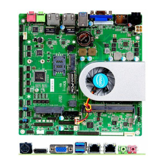
Page 9: Layout Diagram
1-3 Layout Diagram For NC6J-xx-6C Series: ATX12V1 SMBUS DC12V Power-in Connector INVERTER1 HDMI Port DDR4 SODIMM1 VGA Port Header VGA Port LVDS1 CPUFAN USB 3.0 Ports SATA1 RJ-45 LAN Port F_USB30 (LAN1) *F_USB31 SIM1 USB 2.0 FP_USB Full-size Mini-PCIE Ports Connector GPIO1 (USB20) - Page 10 For NC6J-xx-2L Series: ATX12V1 SMBUS DC12V Power-in Connector INVERTER1 HDMI Port DDR4 SODIMM1 VGA Port Header VGA Port LVDS1 CPUFAN USB 3.0 Ports RJ-45 SATA1 LAN Port (LAN1) F_USB30 *F_USB31 SIM1 RJ-45 Full-size Mini-PCIE LAN Port FP_USB Connector (LAN2) GPIO1 F_USB20 Line-out PARALLEL1...
- Page 11 Motherboard Jumper Position JBAT JPCOM1 JPCOM2 COPEN1...
- Page 12 Jumpers Jumper Name Description JBAT Pin 1&2:Clear CMOS RAM Settings 4-pin Block Pin 3&4:Flash Override LCD Panel VCC 3.3V/5V/12V Select 4-pin Block LCD Backlight VCC 5V /12V Select 3-pin Block JPCOM1 COM1 Header Pin9 Function Select 4-pin Block JPCOM2 COM2 Header Pin9 Function Select 4-pin Block MPE Slot VCC Select 3-pin Block...
- Page 13 Headers Header Name Description JW_FP1 Front Panel Header(PWR LED/ 9-pin Block LED/Power Button /Reset) FP_AUDIO1 Front Panel Audio Header 9-pin Block SPEAK_CON 3W Amplifier Header 4-pin Block FP_USB USB 2.0 Port Header 4-pin Block *F_USB20 USB 2.0 Port Header 9-pin Block F_USB30 USB 3.0 Port Header 19-pin Block...
-
Page 14: Chapter 2 Hardware Installation
Chapter 2 Hardware Installation 2-1 Jumper Setting Pin 1&2 of JBAT (4-pin): Clear CMOS Setting → Pin 1&2 of JBAT Clear CMOS Setting Pin 1 1-2 Open: Normal; JBAT Pin 1 1-2 Closed: Clear CMOS Pin 3&4 of JBAT (6-pin): Flash Override →... - Page 15 JP1 (4-pin): LCD Panel VCC 3.3V/5V /12V Select → LCD Panel VCC 5 3 1 5 3 1 6 4 2 6 4 2 2-4 Closed: 3-4 Closed: 4-6 Closed: VCC=3.3V; VCC= 12V. VCC= 5V; JP2 (3-pin): LCD Backlight VCC 5V/12V Select →...
- Page 16 JPCOM2 (4-pin): COM2 Header Pin9 Function Select → JPCOM2 COM2 Header Pin-9 JPCOM2 2-4 Closed: 3-4 Closed: 4-6 Closed: RI=RS232; RI= 5V; RI= 12V. JP5 (3-pin): MPE Slot VCC Select → MPE Slot VCC Select 1-2 Closed: MPE Slot VCC= 3VSB; 2-3 Closed: MPE Slot VCC=3.3V.
-
Page 17: Connectors & Headers
COPEN1 (2-pin): Case Open Message Display Function Select 1-2 Open: 1-2 Closed: Normal (Default); Case Open. COEPN1 Pin (1-2) Close: When Case Open function pin short to GND, the Case Open function was detected. When Used, needs to enter BIOS and enable ‘Case Open Detect’ function. - Page 18 For NC6J-xx-6C Series: USB 2.0 USB 3.0 Ports Ports HDMI Port VGA Port DC12V Power-in Connector LAN1: RJ-45 Line-OUT LAN Port Icon Name Function For user to connect compatible power DC-in 12V Power adapter to provide power supply for the Connector system.
- Page 19 (2) DCIN1 (4-pin block): DC12V Power-in Connector DCIN1 (3) ATX12V1 (4-pin block): ATX12V Type Power Connector ATX12V1...
- Page 20 (4) SATA (7-pin block):SATAIII Port connector This connector is a high-speed SATAIII port that supports 6GB/s transfer rate. Pin No. Definition SATA (5) SATAPWR(4-pin): SATA Hard Disk Power-out Connector SATAPWR (6) CPUFAN (4-pin): FAN Connector CPUFAN...
-
Page 21: Headers
2-2-2 Headers (1) JW_FP1 (9-pin): Front Panel Header HDDLED+ PWRLED+ HDDLED- PWRLED- PWRBTN RSTSW JW_FP1 (2) FP_AUDIO1 (9-pin): Line-Out, MIC-In Header This header connects to Front Panel Line-out, MIC-In connector with cable. Pin 1 FP_AUDIO1... - Page 22 (3) SPEAK_CON (4-pin): 3W Amplifier Header Pin1 Pin No. Definition SPEAK_CON (4) FP_USB (4-pin): USB 2.0 Port Header FP_USB Pin 1 -DATA +DATA (5) F_USB20 (9-pin): USB 2.0 Port Header *F_USB20 Pin 1...
- Page 23 (6) F_USB30/F_USB31 (9-pin): USB 3.0 Port Header GND2 GND1 SSTX2+ SSTX2- SSTX1+ SSTX1- F_USB30 GND3 GND0 SSRX2+ *F_USB31 SSRX1+ SSRX2- VBUS SSRX1- VBUS Pin 1 (7) PS2_CON1 (6-pin): PS/2 Keyboard & Mouse Header Pin 1 PS2_CON1 KB_CLK KB_DATA MS_DATA PS2_VCC MS_CLK (8) SMBUS (5-Pin): SMBUS Header SMBUS...
- Page 24 (9) COM1/COM2 (9-Pin): Serial Port Header NC6J-xx-2L series: COM1/COM2 both support RS232/422/485 function; NC6J-xx-6C series: COM1 supports RS232/422/485 function; COM2 supports RS232 function only. *RS422 *RS485 Pin NO. RS232 (optional) (optional) Pin 1 DATA- Pin 2 DATA+ Pin 3 Pin 4 Pin 5 Pin6 Pin 6...
- Page 25 (11) COM3-COM6/ COM7-COM10 (40-Pin): RS232 Serial Port Header Block *COM7-COM10 COM3-COM6 COM3-COM6 Pin NO. RS232 Pin NO. RS232 COM7-COM10 Pin NO. RS232 Pin NO. RS232 Pin 1 DCD3 Pin 2 DSR3 Pin 1 DCD7 Pin 2 DSR7 SIN3 RTS3 Pin3 Pin 4 Pin3 SIN7...
- Page 26 (12) PARALLEL1 (25-pin): Parallel Port Header Pin 1 PARALLEL1 Pin 13 Pin NO. Pin Definition Pin NO. Pin Definition STB- AFD- Pin 1 Pin 14 PRD0 ERR- Pin 2 Pin 15 PRD1 INIT- Pin 3 Pin 16 PRD2 SLIN- Pin 4 Pin 17 PRD3 Pin 5...
- Page 27 (13) GPIO1(10-pin): GPIO Header GPIO1 Pin 1 GPIO_30 GPIO_31 GPIO_32 GPIO_33 GPIO_35 GPIO_34 GPIO_37 GPIO_36 (14) VGA1 (12-pin): VGA Header Pin No. Definition VCC5(Reserved) VGA_VSYNC VGA_HSYNC GND_RED RED_VGA GND_GRN GRN_VGA VGA1 GND_BLUE BLUE_VGA DDC_DATA DDC_CLK...
- Page 28 (15) LVDS1 (30-Pin): 24-bit dual channel LVDS Header Pin 1 Pin 2 LVDS1 Pin NO. Pin Define Pin NO. Pin Define Pin 1 LVDS_VCC Pin 2 LVDS_VCC Pin 3 LVDS_VCC Pin 4 Pin 5 Pin 6 Pin 7 LVDSA_DATAN0 Pin 8 LVDSA_DATAP0 Pin 9 LVDSA_DATAN1...
- Page 29 (16) INVERTER1 (6-Pin): LVDS1 Inverter Header INVERTER1 Pin No. Definition BKLT_PWR1 BKLT_PWR2 BKLT_EN BKLT_PWM GND1 GND2 Warning! Find Pin-1 location of the inverter and make sure that the installation direction is correct! Otherwise serious harm will occur to the board/display panel!! (17) JP3 (2-pin): LVDS Panel Brightness Adjustment Header :...
-
Page 30: Chapter 3 Introducing Bios
Chapter 3 Introducing BIOS Notice! The BIOS options in this manual are for reference only. Different configurations may lead to difference in BIOS screen and BIOS screens in manuals are usually the first BIOS version when the board is released and may be different from your purchased motherboard. -
Page 31: Bios Menu Screen
3-2 BIOS Menu Screen The following diagram show a general BIOS menu screen: Menu Bar General Help Items Menu Items Current Setting Value Function Keys 3-3 Function Keys In the above BIOS Setup main menu of, you can see several options. We will explain these options step by step in the following pages of this chapter, but let us first see a short description of the function keys you may use here: ... -
Page 32: Getting Help
Press <+>/<–> keys when you want to modify the BIOS parameters for the active option. [F1]: General help. [F2]: Previous value. [F3]: Optimized defaults. [F4]: Save & Exit. Press <Esc> to quit the BIOS Setup. 3-4 Getting Help Main Menu The on-line description of the highlighted setup function is displayed at the top right... -
Page 33: Main Menu
3-6 Main Menu Main menu screen includes some basic system information. Highlight the item and then use the <+> or <-> and numerical keyboard keys to select the value you want in each item. System Date Set the date. Please use [Tab] to switch between date elements. System Time Set the time. -
Page 34: Advanced Menu
3-7 Advanced Menu CPU Configuration Press [Enter] to view current CPU configuration and make settings for the following sub-items: Intel Virtualization Technology The optional settings: [Enabled]; [Disabled]. When set as [Enabled], a VMM can utilize the additional hardware capabilities provided by Vanderpool Technology. - Page 35 The optional settings: [Disabled]; [Enabled]. CPU C States Use this item to enable or disable CPU Power Management. When set as [Enabled], it allows CPU to go to C states when it’s not 100% utilized. The optional settings: [Disabled]; [Enabled]. Package C State Limit Use this item to select maximum package C State Limit setting.
- Page 36 Use this item to enable or disable ME FW Image Re-Flash function. The optional settings: [Disabled]; [Enabled]. * In the case that user needs to update ME firmware, user should set ‘ME FW Image Re-Flash’ as [Enabled], save the settings and exit. The system will turn off and reboot after 4 seconds.
- Page 37 USB S3/S4 Wake-up Use this item to enable or disable USB Wake-up from S3/S4 state. * Note: This function is supported when ‘ERP Support’ is set as [Disabled]. USB S5 Power Use this item to enable or disable USB power after power shutdown. * Note: This function is supported when ‘ERP Support’...
- Page 38 The optional settings are: [IO=2F8h; IRQ=3]; [IO=3F8h; IRQ=3,4,5,6,7, 9,10,11,12]; [IO=2F8h; IRQ=3,4,5,6,7, 9,10,11,12]; [IO=3E8h; IRQ=3,4,5,6,7, 9,10,11,12]; [IO=2E8h; IRQ=3,4,5,6,7, 9,10,11,12] for ‘Serial Port 2 Configuration’. The optional settings are: [IO=3E8h; IRQ=10]; [IO=3F8h; IRQ=3,4,5,6,7, 9,10,11,12]; [IO=2F8h; IRQ=3,4,5,6,7, 9,10,11,12]; [IO=3E8h; IRQ=3,4,5,6,7, 9,10,11,12]; [IO=2E8h; IRQ=3,4,5,6,7, 9,10,11,12]; [IO=3E0h; IRQ=3,4,5,6,7, 9,10,11,12];...
- Page 39 Use this item to enable or disable serial port (LPT/LPTE). The optional settings are: [Disabled]; [Enabled]. Change Settings Use this item to select an optimal setting for super IO device. The optional settings are: [Auto]; [IO=378h; IRQ=7]; [IO=378h; IRQ=5,6,7,9,10,11,12]; [IO=278h; IRQ=5,6,7,9,10,11,12]; [IO=3BCh;...
- Page 40 CPUFAN Full-Speed Temperature Use this item to set CPUFAN full speed temperature. Fan will run at full speed when above the preset temperature. CPUFAN Full-Speed Duty Use this item to set CPUFAN full speed duty. Fan will run at full speed when above the pre-set duty.
- Page 41 The optional settings are: [IO=250h; IRQ=11]; [IO=240h; IRQ=5,10,11]; [IO=248h; IRQ=5,10,11]; [IO=250h; IRQ=5,10,11]; [IO=258h; IRQ=5,10,11] for ‘Serial Port 9 Configuration’. The optional settings are: [IO=258h; IRQ=11]; [IO=240h; IRQ=5,10,11]; [IO=248h; IRQ=5,10,11]; [IO=250h; IRQ=5,10,11]; [IO=258h; IRQ=5,10,11] for ‘Serial Port 10 Configuration’. Serial Port Console Redirection Press [Enter] to make settings for the following sub-items: COM1 Console Redirection...
- Page 42 VT-UTF8 Combo Key Support The optional settings are: [Disabled]; [Enabled]. Recorder Mode The optional settings are: [Disabled]; [Enabled]. Resolution 100x31 The optional settings are: [Disabled]; [Enabled]. Legacy OS Redirection Resolution The optional settings are: [80x24]; [80x25]. Putty Keypad The optional settings are: [VT100]; [LINUX]; [XTERMR6]; [SCO]; [ESCN]; [VT400].
- Page 43 The default setting is: [8]. *This item may or may not show up, depending on different configuration. Parity The default setting is: [None]. *This item may or may not show up, depending on different configuration. Stop Bits The default setting is: [1]. *This item may or may not show up, depending on different configuration.
- Page 44 The optional settings range from [1] to [50]. CSM Configuration Press [Enter] to make settings for the following sub-items: Compatibility Support Module Configuration Network This item controls the execution of legacy PXE OpROM. The optional settings are: [Do not launch]; [Legacy]. Storage This item controls the execution of UEFI and Legacy Storage OpROM.
- Page 45 Use this item to set USB mass storage device start unit command time-out. The optional settings are: [10 sec]; [20 sec]; [30 sec]; [40 sec]. Device Power-up Delay Use this item to set maximum time the device will take before it properly reports itself to the host controller.
-
Page 46: Chipset Menu
3-8 Chipset Menu System Agent (SA) Configuration Press [Enter] to make settings for the following sub-items: VT-d Use this item to enable or disable VT-d capability. The optional settings are: [Enabled]; [Disabled]. * This item might not be available depending on configuration. ... - Page 47 Use this item to select DVMT 5.0 pre-allocated (fixed) graphics memory size used by the internal graphics device. The optional settings are: [32M]; [64M]; [96M]; [128M]; [160M]; [192M]; [224M]; [256M]; [288M]; [320M]; [352M]; [384M]; [416M]; [448M]; [480M]; [512M]; [1024MB]; [1538MB]; [2048MB]; [4M]; [8M]; [12M]; [16M]; [20M]; [24M]; [28M]; [32M/F7]; [36M]; [40M];...
- Page 48 Memory Configuration Press [Enter] to view current memory configuration. ► PCH-IO Configuration Press [Enter] to make settings for the following sub-items: USB Controller Use this item to enable or disable this USB physical connector (physical port). Once disabled, any USB devices plugged into this connector will not be detected by BIOS or OS.
-
Page 49: Security Menu
3-9 Security Menu Security menu allow users to change administrator password and user password settings. Administrator Password Press [Enter] to create new administrator password. Press again to confirm the new administrator password. User Password Press [Enter] to create new user password. Press again to confirm the new user password. -
Page 50: Boot Menu
3-10 Boot Menu Boot Configuration Setup Prompt Timeout Use this item to set number of seconds to wait for setup activation key. Bootup Numlock State Use this item to select keyboard numlock state. The optional settings are: [On]; [Off]. Quiet Boot The optional settings are: [Disabled];... -
Page 51: Save & Exit Menu
3-11 Save & Exit Menu Save Options Save Changes and Reset This item allows user to reset the system after saving the changes. Discard Changes and Reset This item allows user to reset the system without saving any changes. Default Options Restore Defaults Use this item to restore /load default values for all the setup options. - Page 52 Launch Internal EFI shell application (shell.efi). Lauch EFI Shell from filesystem device Use this item to launch EFI shell application (shell.efi) from one of the available filesystem device.
Need help?
Do you have a question about the NC6J Series and is the answer not in the manual?
Questions and answers