
Related Manuals for Tosot MONA-20


Summary of Contents for Tosot MONA-20
- Page 1 Owner's Manual Original Instructions Local air conditioner Model: MONA-20 Thank you for choosing our product. Please read this Owner’s Manual carefully before operation and retain it for future reference.
-
Page 3: Table Of Contents
Content Operation Notices The Refrigerant ..................... Safety Warning ..................... Operation Environment ..................Part's Name ......................Operation Guide Operation Introduction for Control Panel ............... Using the remote controller ................... Buttons on Remote Controller ................Introduction for Icons on Display Screen ............... Introduction for Buttons on Remote Controller ............ - Page 4 Explanation of Symbols Indicates a hazardous situation that, if not avoided, will DANGER result in death or serious injury. Indicates a hazardous situation that, if not avoided, could WARNING result in death or serious injury. Indicates a hazardous situation that, if not avoided, may CAUTION result in minor or moderate injury.
-
Page 5: The Refrigerant
Appliance filled with flammable gas R290. Before install and use the appliance, read the owner’s manual first. Before install the appliance, read the installation manual first. Before repair the appliance, read the service manual first. The Refrigerant To realize the function of the air conditioner unit, a special refrigerant circulates in the system. -
Page 6: Safety Warning
Safety Warning ● This appliance can be used by children aged from 8 years and above and persons with reduced physical, sensory or mental capabilities or lack of experience and knowledge if they have been given supervision or instruction concerning use of the appliance in a safe way and understand the hazards involved. -
Page 7: Operation Environment
Safety Warning ● Do not through sundries into the air duct. If there are sundries get into the air duct, please contact the professionals to deal with it. ● Do not use an extension cord. Operation Environment ● r i a i t i t a r i h t... -
Page 8: Part's Name
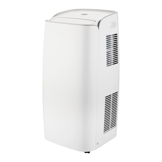
Part's Name Controller panel Guide louver Handels Castors Filter Air inlet Drainage port(Middle) Power cord Power cord hooks Drainage port(Lower) WIFI Remote controller NOTICE: Some installation accessories can't be discarded. -
Page 9: Operation Introduction For Control Panel
Operation Introduction for Control Panel Name of control panel Dual-8 nixie tube + / - button Cool mode indicator Swing indicator Wifi indicator Dry mode indicator Fan mode indicator Swing button Heat mode indicator Wifi button (Cool&Heat Unit only) Fan speed indicator Fan button ON/OFF button Mode button... - Page 10 Operation Introduction for Control Panel Mode button Press this button and the mode will circulate according to below sequence: Cool Heat (Cool&Heat Unit only) Cool: Under this mode, cooling mode indicator is bright. Dual-8 nixie tube displays set temperature. Temperature setting range is 16 °C~30°C Dry: Under this mode, drying mode indicator is bright.
-
Page 11: Using The Remote Controller
Using the remote controller This is a general use remote controller, it could be used for the air conditioners with multifunction; For some function, which the model doesn't have, if press the corresponding button on the remote controller that the unit will keep the original running status. -
Page 12: Buttons On Remote Controller
Buttons on remote controller ON/OFF button ▲ button MODE button SWING button button FAN button TIMER OFF button CLOCK button TIMER ON button SLEEP button TEMP button TURBO button X-FAN button WiFi button button Introduction for icons on display screen Set fan speed I feel Send signal... -
Page 13: Introduction For Buttons On Remote Controller
Introduction for buttons on remote controller Note: ● This is a general use remote controller, it could be used for the air conditioners with multifunction; For some function, which the model doesn't have, if press the corresponding button on the remote controller that the unit will keep the original running status. - Page 14 Introduction for buttons on remote controller button Press this button to decrease set temperature. Holding it down above 2 seconds rapidly decreases set temperature. In AUTO mode, set temperature is not adjustable. FAN button This button is used for setting Fan Speed in the sequence that goes from AUTO, , to , then back to Auto.
- Page 15 Introduction for buttons on remote controller SLEEP button Press this button to go into the SLEEP operation mode. Press it again to cancel this function. This function is available in COOL, HEAT (Only for models with heating function) to maintain the most comfortable temperature for you. TEMP button Press this button, you can see indoor set temperature, indoor ambient temperature on indoor unit’s display.
-
Page 16: Function Introduction For Combination Buttons
Introduction for buttons on remote controller button Press this button to achieve the on and off of health and scavenging functions in operation status. Press this button for the first time to start scavenging function; LCD displays " ". Press the button for the second time to start health and scavenging functions simultaneously;... -
Page 17: Operation Guide
Operation guide After putting through the power, press "ON/OFF" button on remote controller to turn on the air conditioner. Press "MODE" button to select your required mode: AUTO, COOL, DRY, FAN, HEAT. Press "▲" or " " button to set your required temperature. (Temperature can’t be adjusted under auto mode). -
Page 18: Clean And Maintenance
Clean and Maintenance WARNING: ● Before cleaning the air conditioner, please turn off the unit and disconnect power. Otherwise, it may cause electric shock. ● Do not wash air conditioner with water. Otherwise, it may cause electric shock. ● Do not use volatile liquid (such as thinner or gas) to clean the air conditioner. Otherwise, it may damage the appearance of air conditioner. - Page 19 Clean and Maintenance NOTICE dust in the operation environment, you can increase clean frequency. Clean heat discharge pipe Remove the heat discharge pipe from air conditioner, clean and dry it , and then reinstall it. (For the method of installation and removal , please refer to the instruction for "Installation and disassembly of heat discharge pipe").
-
Page 20: Malfunction Analysis
Malfunction analysis Please check below items before asking for maintenance. If the malfunction still Phenomenon Troubleshooting Solution ● Power failure? ● Wait after power recovery. ● Is plug loose? ● Reinsert the plug. ● Whether the air switch is trip- ●... - Page 21 Malfunction analysis Phenomenon Troubleshooting Solution ● Whether air outlet or air inlet is ● Eliminate the obstacles. blocked? ● Under heating mode, whether ● The unit will stop blowing indoor temperature increase fan after reaching set set temperature? temperature. ● In order to prevent cold air, No air blowed ●...
- Page 22 Malfunction analysis Malfunction code ERROR Troubleshooting CODE Please contact qualified professionals for service. Please contact qualified professionals for service. Please contact qualified professionals for service. Please contact qualified professionals for service. 1.Check if the unit is under high-temperature and high-humidity environment; if ambient temperature is too high, power off the unit and then energize it for operation after the ambient temperature drops to 35℃below.
-
Page 23: Installation Precaution
Installation Precaution WARNING: ● Observe all governing codes and ordinances. ● Do not use damaged or non-standard power cord. ● Be caution during installation and maintenance. Prohibit incorrect operation to prevent electric shock, casualty and other accidents. Selection of installation location Basic requirement Installing the unit in the following places may cause malfunction. -
Page 24: Preparation Before Installation
The appliance shall be installed in accordance with national wiring regulations. To be in compliance with IEC 61000-3-11, impedance value of power-supply system connected to product must be less than or eq ual to the allowable maximum value of |Zsys| in the following sheet: 0.13 MONA -20 Preparation before Installation... -
Page 25: Install Power Cord Hooks
Optional 5 Optional 4 Joint H Drainage hose Plastic Cover Joint G Joint F Tools needed for installation Cross screwdriver Straight screwdriver Guge Scissors Pencil Install Power cord Hooks ● Assemble the power cord hooks at the back of the unit with screws (the direction of power cord hooks is as shown in following fig). -
Page 26: Removing Collected Water
● Wind the power cord around the power cord hooks . Removing Collected Water There are 2 ways to remove collected water: Use the drainage option from the lower hole. In Cool, Dry or Heat mode operating, the condensation water will be drained to the chassis. - Page 27 Removing Collected Water Use the continuous drainage option from the middle hole NOTICE: Water can be automatically emptied into a floor drain by attaching 14mm inner diameter hose (not included). Remove the continuous drain cap 1 by turning it counter clockwise then remove the rubber stopper 2 from the spout.
-
Page 28: Installation Of Heat Discharge Pipe
Installation of Heat Discharge Pipe Note of Installingheat discharge pipe correct correct correct wrong ● The length of the heat discharge pipe is less than 1m. It is recommended to use it with shortest length. When installing,heat discharge pipe should be as flat as possible. Don’t prolong the pipe or connect it with other heat discharge pipe. - Page 29 Installation of Heat Discharge Pipe should not be over 130cm from floor). would easily cause malfunction.)
- Page 30 Installation of Heat Discharge Pipe Optional 1: Installation in a double window 1. Connect joint B to joint C . Joint B Joint C 2. Rotate joint A and joint B+C into the two ends of heat discharge pipe. Joint A Heat discharge pipe Joint B+C 3.
- Page 31 Installation of Heat Discharge Pipe Optional 2-1: Installation in a double-hung sash window 1. Attach the insect guard net to the window panel. 2. Cut the sponge A (adhesive type) to the proper length and attach it to the window stool and to the bottom of sash. Sponge A 3.
- Page 32 Installation of Heat Discharge Pipe Inner width of the window:20.5" (520mm)- 38.5" (980mm) Use the window panel and the adjustment panel. (1) Open the window sash and place the window panel on the window sill. (2) Slide the adjustment panel to fit the window frame width. (3) Secure the window panel to the sill with screws.
- Page 33 Installation of Heat Discharge Pipe 4. Close the window sash securely against the Window panel. 5. Stuff the sponge B between the glass and the window to prevent air and insects from getting into the room. 6. Attach the bracket with a screw. Bracket...
- Page 34 Installation of Heat Discharge Pipe 7. Connect joint B to joint C . Joint B Joint C 8. Rotate joint A and joint B+C into the two ends of heat discharge pipe. Clockwise Anti-clockwise Joint A Heat discharge pipe Joint B+C 9.
- Page 35 Installation of Heat Discharge Pipe Optional 2-2: Installation in a sliding sash window 1. Attach the insect guard net to the window panel. 2. Cut the sponge A (adhesive type) to the proper length and attach it to the window frame and to the side of sash. Sponge A 3.
- Page 36 Installation of Heat Discharge Pipe Inner height of the window:20.5" (520mm)- 38.5" (980mm) Use the window panel and the adjustment panel. (1) Open the window sash and place the window panel on the window frame. (2) Slide the adjustment panel to fit the window frame height. (3) Secure the window panel to the window frame with screws.
- Page 37 Installation of Heat Discharge Pipe 4. Close the window sash securely against the Window panel. 5. Stuff the foam seal B between the glass and the window to prevent air and insects from getting into the room. 6. Attach the bracket with a screw. Bracket...
- Page 38 Installation of Heat Discharge Pipe Connect joint B to joint C . Joint B Joint C 8. Rotate joint A and joint B+C into the two ends of heat discharge pipe. Clockwise Anti-clockwise Joint A Heat discharge pipe Joint B+C 9.
- Page 39 Installation of Heat Discharge Pipe -1 Installation in the window 1. Rotate joint A and joint D into the two ends of heat discharge pipe. Then, rotate joint E to joint D, connect tightly. Joint E Joint A Heat discharge pipe Joint D 2.
- Page 40 Installation of Heat Discharge Pipe Optional 3-2: Installation in the wall 1. Rotate joint A and joint D into the two ends of heat discharge pipe. Joint A Heat discharge pipe Joint D Insert joint A of heat Clasp discharge pipe (the The side with "TOP"...
- Page 41 Installation of Heat Discharge Pipe Optional 3-3: Installation in immovable window 1. Rotate joint A into the ends of heat discharge pipe. Joint A Heat discharge pipe 2. If the window is immovable, cut a hole to install joint F and joint G tightly. Inside Outside Joint G...
- Page 42 Installation of Heat Discharge Pipe 4. Insert joint A of heat discharge pipe (the side with "TOP" is upwards) into the groove until you hear a sound. Clasp the side with "TOP" is upwards Groove...
- Page 43 I nstallation of Heat Discharge Pipe Optional 4-1: Installation in the window 1. Fold the rear joint inwards unit these two clasps have tightly connected the rear joint together. 2. Rotate joint A and joint F into the two ends of heat discharge pipe.
- Page 44 Installation of Heat Discharge Pipe Optional 4-2: Installation in immovable window 1. Rotate joint A into the ends of heat discharge pipe. Joint A Heat discharge pipe If the window is immovable, cut a hole to install joint F and joint G tightly. Inside Outside Joint G...
- Page 45 Installation of Heat Discharge Pipe 4. Insert joint A of heat discharge pipe (the side with "TOP" is upwards) into the groove until you hear a sound. Clasp the side with "TOP" is upwards Groove...
-
Page 46: Disassembly Of Heat Discharge Pipe
Disassembly of Heat Discharge Pipe Optional 1: Disassemble for installation in double window Remove joint A: Press the clasp and lift joint A upwards to remove it. Clasp Upwards Disassemble Joint A Remove joint B+C from outdoors. Joint B+C... - Page 47 Disassembly of Heat Discharge Pipe Optional 2: Disassemble for installation in sash window 1. Remove joint A: Press the clasp and lift joint A upwards to remove it. Clasp Upwards Disassemble Joint A 2. Remove the window adapter. Pull out and remove the window adapter by pushing down two “PUSH”...
- Page 48 Disassembly of Heat Discharge Pipe Optional 3-1: Disassembly for installation in window 1. Remove joint A: 2. Remove joint D: Press the clasp and lift joint A upwards to remove joint D from joint E. remove it. Clasp Upwards Disassemble Joint A Joint D Joint E...
- Page 49 Disassembly of Heat Discharge Pipe 3. When heat discharge pipe is removed, Install the plastic cover into joint D in case of the insect into the house. Optional 3-3: Disassembly for installation in immovable window 1. Remove joint A: Press the clasp and lift joint A upwards to remove it. Clasp Upwards Disassemble...
- Page 50 Disassembly of Heat Discharge Pipe When heat discharge pipe is removed, Install the plastic cover into joint F in case of the insect into the house . Plastic Cover Optional 4-1: Disassembly for installation in window Remove joint A: 2. Remove joint F: Press the clasp and lift joint A upwards to remove joint F from joint H.
- Page 51 Disassembly of Heat Discharge Pipe Optional 4-2: Disassembly for installation in immovable window 1. Remove joint A: Press the clasp and lift joint A upwards to remove it. Clasp Upwards Joint A Disassemble 2. Remove the heat discharge pipe from the joint F. When heat discharge pipe is removed, Install the plastic cover into joint F in case of the insect into the house .
-
Page 52: Operation Test
Operation Test ● Put through the power supply and then press ON/OFF button on remote contro- ller to start the unit. ● Press mode button to select auto, cooling, drying, fan or heating function, and then check if the unit operates normally. ●... -
Page 53: Electric Schematic Diagram
Electric Schematic Diagram MONA-20 The Electric schematic diagram are subject to change without notice. Please refer to which one on the unit. ROOM TEMP. TUBE TEMP. OUTTUBE TEMP. WATER MOTOR SENSOR SENSOR SENSOR RECEIVER POWER BN(BK) YEGN BOARD BU(WH) YEGN(GN) -
Page 54: Specialist's Manual
Specialist’s Manual Aptitude requirement for maintenance man(repairs should be done only be specialists). a. All the work men who are engaging in the refrigeration system should bear the valid certification awarded by the authoritative organization and the qualification for dealing with the refrigeration system recognized by this industry. b. - Page 55 Specialist’s Manual Refrigeration equipment Checking Where electrical components are being changed, they shall be fit for the purpose and to the correct specification. At all times the manufacturer’s maintenance and service guidelines shall be followed. If in doubt, consult the manufacturer’s technical department for assistance.
- Page 56 Specialist’s Manual Ensure that the apparatus is mounted securely. Ensure that seals or sealing materials have not degraded to the point that they no longer serve the purpose of preventing the ingress of flammable atmospheres. Replacement parts shall be in accordance with the manufacturer’s specifications. NOTE : The use of silicon sealant can inhibit the effectiveness of some types of leak detection equipment.
- Page 57 Specialist’s Manual The refrigerant charge shall be recovered into the correct recovery cylinders. For appliances containing flammable refrigerants, the system shall be “flushed” with OFN to render the unit safe. This process may need to be repeated several times. Compressed air or oxygen shall not be used for purging refrigerant systems. For appliances containing flammable refrigerants, flushing shall be achieved by breaking the vacuum in the system with OFN and continuing to fill until the working pressure is achieved, then venting to atmosphere, and finally pulling down to a vacuum.
- Page 58 Specialist’s Manual f) Make sure that cylinder is situated on the scales before recovery takes place. g) Start the recovery machine and operate in accordance with manufacturer's instructions. h) Do not overfill cylinders. (No more than 80 % volume liquid charge). i) Do not exceed the maximum working pressure of the cylinder, even temporarily.
- Page 60 GREE ELECTRIC APPLIANCES, INC. OF ZHUHAI Add: West Jinji Rd, Qianshan, Zhuhai,Guangdong, China, 519070 Tel: (+86-756) 8522218 Fax: (+86-756) 8669426 E-mail: gree@gree.com.cn www.gree.com 66129934158...
Need help?
Do you have a question about the MONA-20 and is the answer not in the manual?
Questions and answers