Subscribe to Our Youtube Channel
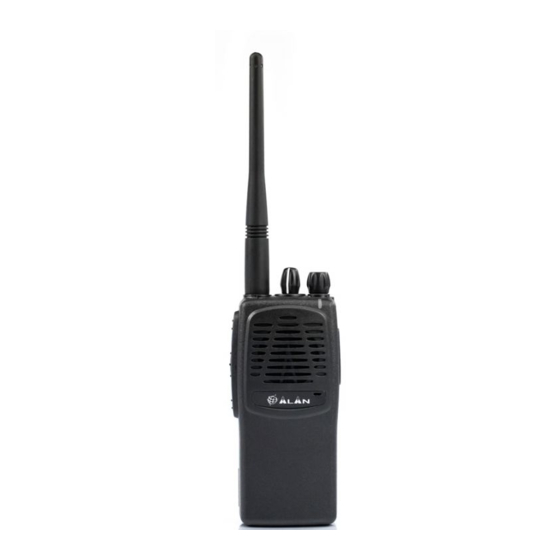
Summary of Contents for Alan HP70L
- Page 1 HP70L / HP70H Service Manual ALAN HP70L / HP70H Portable VHF Transceiver Service Manual Copyright © 2006 by CTE International Italy. All rights reserved...
-
Page 2: Table Of Contents
2.6.b CTCSS Tone Encoder / Digital Code Squelch (DCS) Encoder ................7 2.6.c Selective call ................................7 2.6.d Scrambler ................................7 2.7 Battery ....................................7 3 ADJUSTMENTS HP70L..........................8 3.1 General ....................................8 3.2 Needed Equipment: ................................8 3.3 Programming the radio .................................9 3.4 Synthesizer/Transmitter VCO Check ..........................9 3.5 Frequency Adjustment .................................9... -
Page 3: Technical Specifications
ETS 300-086 § IEC 529 IP54 and MIL STD 810 C/D/E 1.2 Specifications table GENERAL Frequency ALAN HP70 L: 66 ÷ 77 MHz ALAN HP70 H: 77 ÷ 88 MHz Operational bandwidth 11 MHz Number of channels Channel spacing 12,5 / 20 / 25kHz... -
Page 4: Circuit Description
Service Manual 2 CIRCUIT DESCRIPTION 2.1 General information The information in this section is common for both HP70L and HP70H radios. The HP70L/H circuitry is divided in the following sections, please refer to the Block Diagram and Schematic Drawings. § Microprocessor/Control §... -
Page 5: Synthesizer
HP70L / HP70H Service Manual 2.3.c Synthesizer The frequency synthesizer is a large scale monolithic integrated circuit Q429. RF output from the active (Receive or Transmit) VCO is coupled to the synthesizer prescaler input at Pin 8. The divide-by-N counter chain in Q429, consisting of the dual-modulus prescaler, swallow counter and programmable counter, divides the VCO signal down to a frequency very close to 5.00 KHz or 6.25 Khz, depending on channel... -
Page 6: Transmitter Audio Circuits
HP70L / HP70H Service Manual 2.4.d Transmitter Audio Circuits The transmitter audio circuits consist of the audio processing circuits, the CTCSS circuits and the DCS circuits. 2.4.e Audio Processing Transmit speed audio is providing by either the internal electric microphone N101 or the external microphone. -
Page 7: Signalling
HP70L / HP70H Service Manual is routed to Pin 2, the input to the audio power amplifier Q221. The output of the audio power amplifier is routed through the earphone jack J401 to the internal speaker E101. 2.6 Signaling 2.6.a... -
Page 8: Adjustments Hp70L
HP70L / HP70H Service Manual 3 ADJUSTMENTS HP70L 3.1 General Adjustment trimmer potentiometer/capacitors in the HP70 VHF Radio: Ref. Designator Used for… RV204 Squelch Level Adj., 25kHz (wide band) spacing. RV205 Squelch Level Adj., 12.5kHz (narrow band) spacing. RP402 Frequency Adj. -
Page 9: Programming The Radio
HP70L / HP70H Service Manual 3.3 Programming the radio 1) Program the radio, as follows: ChName RxFreq TxFreq ChSpace Pwr Dcs/CtcssRx Dcs/CtcssTx SelCall Rx Transpond Call1 Call2 Emergency MonKey Ch.1 66.050 66.075 25 H Ch.2 71.050 71.075 25 H Ch.3 76.950... -
Page 10: Modulation Adjustment
HP70L / HP70H Service Manual 14) Adjust RV401 (HI PWR ADJ) and C1008 for a reading of 4.9 W ±0.1 W. Check to make sure that the transmit current is within 1000 - 1400mA after the adjustment has been made. Check the power on channels 2 and 3. It must be between 4.3 and 5.5W. - Page 11 HP70L / HP70H Service Manual 39) Adjust the squelch control RV205 until the BUSY LED (Green) turns ON. 40) Set the RF generator to a RF level of -80dBm, signal with 1kKHz tone and 1.5kKHz deviation at 71.050MHz. 41) Adjust the RF signal generator level to obtain 12dB SINAD reading. It must be below -117.5dBm 42) Adjust RV205 counter clockwise slowly just the BUSY LED goes on.
-
Page 12: Adjustments Hp70H
HP70L / HP70H Service Manual 4 ADJUSTMENTS HP70H 4.1 General Adjustment trimmer potentiometer/capacitors in the HP70 VHF Radio: Ref. Designator Used for… RV204 Squelch Level Adj., 25kHz (wide band) spacing. RV205 Squelch Level Adj., 12.5kHz (narrow band) spacing. RP402 Frequency Adj. -
Page 13: Programming The Radio
HP70L / HP70H Service Manual 4.3 Programming the radio 1) Program the radio, as follows: ChName RxFreq TxFreq ChSpace Pwr Dcs/CtcssRx Dcs/CtcssTx SelCall Rx Transpond Call1 Call2 Emergency MonKey Ch.1 77.500 77.075 25 H Ch.2 82.050 82.075 25 H Ch.3 87.950... -
Page 14: Modulation Adjustment
HP70L / HP70H Service Manual 59) Adjust RV401 (HI PWR ADJ) and C1008 for a reading of 4.9 W ±0.1 W. Check to make sure that the transmit current is within 1000 - 1400 mA after the adjustment has been made. Check the power on channels 2 and 3. It must be between 4.3 and 5.5W. - Page 15 HP70L / HP70H Service Manual 83) Switch the radio the radio on the channel 5 84) Adjust the squelch control RV205 until the BUSY LED (Green) turns ON. 85) Set the RF generator to a RF level of -80dBm, signal with 1 KHz tone and 1.5 KHz deviation at 82.050MHz.


Need help?
Do you have a question about the HP70L and is the answer not in the manual?
Questions and answers