Table of Contents

Related Manuals for Alaris Medical Systems MedSystem III 2865


Summary of Contents for Alaris Medical Systems MedSystem III 2865
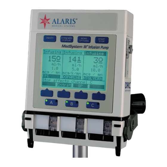
- Page 1 Directions for Use ® MedSystem III Infusion Pump Models 2865/2866 (With Advanced Dose Rate Calculation and Drug List Editor) June 2006 ® MORE START O N / O F F STANDARD OPTIONS STOP DISPLAY ® Infusion Pump ® Alaris Products...
- Page 2 General Contact Information Cardinal Health Cardinal Health Alaris ® Products The Crescent, Jays Close Basingstoke, Hampshire, RG22 4BS, 10221 Wateridge Circle San Diego, California United Kingdom 92121 http://www.cardinal.com/alaris http://www.cardinalhealth.co.uk/alaris Customer Advocacy Clinical and technical feedback. Phone - North America: 800.854.7128, Ext. 7812 E-Mail - North America: CustomerFeedback@cardinal.com E-Mail - International: international.product.complaints@cardinal.com Technical Support - North America...
-
Page 3: Table Of Contents
Table of Contents INTRODUCTION ABOUT THE MEDSYSTEM III ® INFUSION PUMP ..........FEATURES . - Page 4 GETTING STARTED (CONTINUED) DOSE RATE CALCULATOR (DRC) USING A SPECIFIC DRUG NAME (CONTINUED) Programming Dose ..............Changing Volumetric Rate .
- Page 5 GLOSSARY ABBREVIATIONS, ACRONYMS, UNITS OF MEASURE ..........APPENDIX TRUMPET AND START UP CURVES.
- Page 6 T H I S PA G E I N T E N T I O N A L LY L E F T B L A N K Table of Contents Directions for Use ® MedSystem III infusion pump Models 2865/2866...
-
Page 7: Introduction
Introduction ® About MedSystem III Infusion Pump ® MedSystem III infusion pump (instrument) with Drug List Editor is intended for use in today’s growing professional healthcare environment, including healthcare facilities and home care, for use on adults, pediatrics and neonates. Instrument is intended for facilities that utilize infusion pumps for the delivery of fluids, medications, blood and blood products using continuous or intermittent delivery through clinically acceptable... -
Page 8: Features
® About MedSystem III Infusion Pump (Continued) • Display infusion status for rate, volume remaining and volume infused. • Infusions can be programmed to deliver at a specified rate or over a specified period of time. • Secondary mode allows fluids and medications to be delivered at two different rates, sequentially. •... - Page 9 Features (Continued) Six Device Types available Six available Device Types with configurable parameters (maximum and minimum rates, maximum volumes, baseline and maximum pressures, and air-in-line thresholds) to achieve specific clinical applications: General Purpose Operating Room Neonatal General Purpose II Controller Pressure Operating Room II Free-flow Protection Administration Sets contain a cassette that provides...
- Page 10 Features (Continued) Secondary Mode Infusing Secondary A: Secondary Rate 100 ml/h Allows user to program two different rates of infusion to A: Sec VolRem (VR) run sequentially. A: Sec Time(TR) 1 hr A: Sec VolInf(VI) 1 ml since 12:37p 01 Feb 02 Syringe Delivery Stop Affects Secondary Select...
-
Page 11: System Components
System Components FRONT PANEL Instrument Keys Display Screen ® Softkey Pads Channel Indicator Lights Green: MORE START STANDARD O N / O F F • Steady - infusing on AC OPTIONS STOP DISPLAY power ® Infusion Pump • Flashing - infusing on battery power Red: •... - Page 12 System Components (Continued) CONNECTOR PANEL NOTE : When inserting or removing connectors into or from receptacles, avoid excessive force or twisting. To remove AC adapter from pump first remove clip that is on connector. External Power AC Adapter Power Cord External power receptacle con nects 120V/60 Hz three-pronged EXTERNAL...
-
Page 13: Symbols
System Components (Continued) Attaching Pole Clamp To attach pole clamp, position clamp EXTERNAL POWER 6-9 V jaw over mounting surface and turn COMM knob until the clamp is tightened and pump feels secure. When knob is as tight as possible, continued turning will make it click and spin freely without over-tightening. - Page 14 Symbols (Continued) Caution: Federal (U.S.A.) law restricts this device to sale by or on order of a physician. Single-Use Single-Use. Do not reuse. DEHP DEHP in fluid pathway. No DEHP in fluid pathway. Product is latex-free. LATEX Product incorporates SmartSite Needle-Free Valve ports and should not be accessed by a needle.
-
Page 15: Getting Started
Getting Started NOTE: Although instrument is built and tested to exacting CAUTION specifications, it is not intended to replace the supervision of IV infusions by medical personnel. The user should become thoroughly familiar with the features and operation of instrument and exercise vigilance in its utilization. - Page 16 Warnings and Cautions (Continued) WARNING Instrument is designed to stop fluid flow under alarm conditions other than Low Battery and KVO. Periodic patient monitoring must be performed to ensure the infusion is proceeding as expected. WARNING Instrument is a positive pressure delivery system, capable of developing positive fluid pressures to overcome widely varying resistances to flow encountered in practice, including resistances to flow imposed by small gauge catheters, filters and intra-arterial...
- Page 17 Warnings and Cautions (Continued) Parallel Infusions There are no contraindications regarding the use of an instrument with any other positive displacement infusion device when ported together into a common IV site location. To ensure proper instrument performance and to reduce potential injury to the operator, observe the following precautions: •...
- Page 18 Warnings and Cautions (Continued) • For set replacement interval, refer to facility protocol and/or government standards (such as CDC guidelines in the United States). • For IV push medication (put Instrument on hold), clamp tubing above the port. • Flush port(s) per facility protocol. •...
- Page 19 Warnings and Cautions (Continued) • Medical Electrical Equipment needs special precautions WARNING regarding EMC and needs to be installed, put into Use of accessories or cables service and used according to the EMC information other than those specified may provided in the accompanying documents. result in degraded electromagnetic •...
-
Page 20: Preparing The Infusion
Preparing Infusion Connect the container to the IV set. Pressure Dome Prime the Instrument administration set in accordance with the Administration Set Directions for Use. Slide Clamp It is important to prime the set properly to eliminate air bubbles. NOTE: The Model 8631A Syringe Holder is available as an accessory that provides a convenient place to hold syringes while they are being used as containers for IV fluid. -
Page 21: Loading The Set
Loading Set Ensure cassette slide clamp is pulled out (in the closed position) prior to loading. Press to turn pump on. ON/OFF With tubing down, use a 45-degree upward motion to insert cassette into channel. Push on clear portion of cassette until completely seated. Then push in slide clamp flush with entire cassette. -
Page 22: Standard Display Page
Front Panel Overview (Continued) Standard Display Page Status Line Displays infusion status (Infusing; ON/OFF STANDARD MORE START Stopped; Standby; KVO; ALARM; DISPLAY OPTIONS STOP FAULT; SERVICE) for each channel. ® NOTE: Status line in selected Infusion Pump channel is highlighted. Stopped Standby Standby... -
Page 23: Programming Page
Programming Page Se lected channel is indicated by the letter displayed at the beginning of the first five lines. Status Line Displays infusion status for se lected channel. Infusion Rate MORE STANDARD START ON/OFF Volume Remaining DISPLAY OPTIONS STOP ® Infusion Pump Time Remaining Stopped... -
Page 24: To Turn Pump On
Programming Page (Continued) To Turn Pump On Press ON/OFF • Upon start-up, instrument performs an automatic self- test. Listen for a “beep” to ensure that the audio alarm transducer functions properly. • Instrument information page is momentarily displayed. • Continuing to hold down ON/OFF key will keep the Information page on the display. -
Page 25: To Program Infusion
Programming Page (Continued) To Program Infusion With Programming Page displayed: Press Select to choose value to change. • Value is highlighted. Scroll through values using ↑, ↓, Fast ↑ or Fast ↓. • ↑ and Fast ↑ increase highlighted values in single or multiple increments. -
Page 26: To Access Alarm Information
Programming Page (Continued) To Access Alarm Information See the ALARMS, ADVISORIES AND PROMPTS section of this Press affected channel manual for more alarm • Alarm Information page is displayed for that channel. information. To Activate Additional Programming Page Softkeys With the Programming Page displayed: MORE Press OPTIONS... -
Page 27: To Set Primary Volume Remaining (Vr)
Programming Primary Function (Continued) To Set Primary Volume Remaining (VR) Press Select if current VR is desired Stopped A: Primary Rate 100 ml/h A: Pri VolRem (VR) Press ↑, ↓, Fast ↑ or Fast ↓ to change VR. A: Pri Time(TR) 05h 00m A: Pri VolInf(VI) 1 ml... -
Page 28: To Titrate Or Change Primary Rate During Infusion
Programming Primary Function (Continued) To Titrate Or Change Primary Rate During Infusion Press • Programming Page is displayed. • Rate is highlighted. Press ↑, ↓, Fast ↑ or Fast ↓ to change Rate • Value flashes. Press Enter to confirm. •... -
Page 29: Making Changes While Infusing
Programming Primary Function (Continued) To Clear Volume Infused During Infusion (Continued) Press Enter to confirm • Infusion continues with volume infused reset to zero. • Current date and time are entered Press Recall softkey to recall previous VI value, date and time. -
Page 30: To Place A Channel On Standby During Infusion
Making Changes While Infusing (Continued) To Place A Channel On Standby During Infusion NOTE : When a channel is Stopped for two minutes with a cassette in place, a Channel Not In Use advisory sounds. When a channel is on Standby, the advisory does not sound. Stopped NOTE : Infusing channel should always be stopped prior to removing cassette. -
Page 31: Kvo Status
Programming Option (Continued) To Setup An Infusion By Rate/volume Or Volume/time (Continued) Press Select to move highlight to Stopped A: Primary Rate 100 ml/h Setup: Select VR and Time A: Pri VolRem (VR) 500 ml A: Pri Time(TR) 05h 00m A: Pri VolInf(VI) 1 ml Setup: Select VR and Rate... -
Page 32: Secondary Mode
KVO Status (Continued) To Resume Infusion When Vr=0 (KVO) Press Enter to confirm. Press to resume infusion and stop KVO rate. START STOP NOTE: If current infusion rate is set below KVO rate, channel will infuse at the lower rate. Secondary Mode This option allows two different rates of infusion to be administered sequentially. -
Page 33: Preparing The Administration Set And Container
Secondary Mode (Continued) WARNING Preparing The Administration Set And Container Setting a secondary rate over • For Needle-Free sets, attach secondary to upper primary ‘Y’ 275 ml/h may result in concurrent site, below a check valve. flow with the primary container. •... -
Page 34: Programming Secondary Infusion
Secondary Mode (Continued) Programming Secondary Infusion Press Infusing Primary • Primary Programming Page is displayed. A: Primary Rate 50 ml/h A: Pri VolRem (VR) MORE Press OPTIONS A: Pri Time(TR) 09h 00m A: Pri VolInf(VI) 50 ml Press 2° Sec softkey. since 12:37p 01 Feb 02 Press desired function •... -
Page 35: To Set Secondary Rate
Secondary Mode (Continued) To Set Secondary Rate Press Enter to confirm Infusing Secondary Press Select if current rate is desired A: Secondary Rate 100 ml/h A: Sec VolRem (VR) A: Sec Time(TR) ----- Press ↑, ↓, Fast ↑ or Fast ↓ to change Rate. A: Pri VolInf(VI) 200 ml since 12:37p 01 Feb 02... -
Page 36: To Titrate Or Change Secondary Rate During Infusion
Secondary Mode (Continued) To Titrate Or Change Secondary Rate During Infusion NOTE : Channel display on the Standard Display is reverse highlighted. • Secondary Programming Page is displayed. • Rate is highlighted. Infusing Press ↑, ↓, Fast ↑ or Fast ↓ to change rate. Secondary •... -
Page 37: To Start Primary Infusion Before Secondary Completes
Secondary Mode (Continued) To Start Infusion Before Secondary Completes Close regulating clamp on secondary infusion set. WARNING Press Pressing will result in the START STOP • Secondary Programming Page is displayed. remaining secondary medication being delivered at the primary MORE Press OPTIONS rate if the regulating clamp on the... -
Page 38: Programming Drug
Dose Rate Calculator (Drc) Programming Using A Specific Drug Name (Continued) Press CalcOn. • Dose Rate Calculator Programming Page is displayed. • is highlighted. DRUG? Programming Drug NOTE : Changing drug name clears previous values and changes drug concentration and dose r at e par ameter s to parameters appropriate for the selected drug. -
Page 39: Programming Dose
Dose Rate Calculator (Drc) Programming Using A Specific Drug Name (Continued) Programming Concentration (Continued) Press Enter when desired volume is displayed. • VR is automatically set when the diluent volume value is entered but can be changed if desired. • Highlight moves to Dose. NOTE : Calculated rates for infusion are fractional and will be displayed as a fraction on the Standard Display even if Device Type is set for whole numbers. -
Page 40: Clearing The Volume Infused(Vi) And Dose Infused(Di)
Dose Rate Calculator (DRC) Programming using a specific drug name (Continued) Clearing the Volume Infused(VI) and Dose Infused(DI) Press then to reset volume infused to zero. Clear Enter • Highlight moves to DI. Press then to reset dose infused to zero. Clear Enter Open regulating clamp. -
Page 41: Dose Rate Calculator Programming With Drug
Dose Rate Calculator (DRC) Programming using a specific drug name (Continued) Changing DRC values while infusing (Continued) STANDARD Press DISPLAY • Display reverts to Standard Display page after one minute. Verify settings. Verify solution flow from solution container. Dose Rate Calculator Programming with DRUG? NOTE: Dose Rate Programming Page will not d i s p l a y i f c h a n ne l is infusing. -
Page 42: Programming Concentration
Dose Rate Calculator Programming with DRUG? (Continued) Programming Concentration Choose concentration using ↑, ↓, Fast ↑ and Fast ↓ softkeys. Press Enter when desired concentration is displayed. rug concentration • Highlight moves to concentration parameters. parameters Choose desired concentration parameters using ↑, ↓, Gm, mg, mcg, mMol, mEq, mUn, Fast↑... -
Page 43: Changing Volumetric Rate
Dose Rate Calculator Programming with DRUG? (Continued) Changing Volumetric Rate Choose volumetric rate using arrow softkeys if dose calculation is not desired. Press Enter when desired rate is displayed. • When rate is changed, dose is automatically calculated. • Highlight moves to VR. Changing Volumetric Remaining Choose VR value using the arrow softkeys. -
Page 44: Discontinuing Drc Option
Dose Rate Calculator Programming with DRUG? (Continued) Discontinuing DRC Option Press • Dose Rate Calculator Programming Page is displayed. Stopped START Press to stop if infusing. Wt 70.0 KG=154.3LB DOPAMINE STOP A:Conc mg/ 250 ml Press MORE OPTIONS A:Dose mcg/kg/min Press CalcOff. -
Page 45: Device
Device NOTE: The Device Type programming selection affects all three channels. It is not possible to program different Device Types for a channel independently. Stopped There are six Device Types with preset parameters that ml/h accommodate specific clinical applications. They are: VR: 450 General Purpose Operating Room... - Page 46 Device (Continued) To Change Device Type (Continued) • The display switches to a notification screen. • Incompatible Channel(s) indicated. • Choice is given to continue. If Yes, • Incompatible values are cleared. • Display reverts to Standard Display Page. ALARM ----- •...
- Page 47 Device (Continued) To Change Device Type (Continued) Table 1 Default General Controller Operating General Operating Neonatal Parameter Purpose Pressure Room Purpose II Room II Occlusion Baseline Baseline Absolute Baseline Baseline Baseline Detection Threshold Method Occlusion Alarm Baseline+5 psi Baseline +3 psi 3 ft H 2 O Baseline +5 psi Baseline +5 psi Baseline +5 psi Setting...
-
Page 48: Config
Config (Configuration) The Config option allows the user to view and/or change some Infusing Instrument settings. There are five pages in this option. Items shown on page 1 of the Config option can be changed by the user (see Table 2). Pages 2 - 5 of the Config option can only ml/h be changed by qualified personnel using FMS software. -
Page 49: Note Soft Key
Note Soft Key The Note soft key accesses the Special Note Message page. When a Note is programmed, it appears when the pump is turned on. Infusing To Access NOTE(s) ml/h VR: 450 Press STANDARD DISPLAY VI: 50 MORE Press OPTIONS Stop affects channel A TotVol... - Page 50 T H I S PA G E I N T E N T I O N A L LY L E F T B L A N K Getting Started Directions for Use ® MedSystem III infusion pump Models 2865/2866...
-
Page 51: Alarms, Advisories And Prompts
Alarms, Advisories, and Prompts Use this troubleshooting information in conjunction with appropriate hospital procedures. Responding to an advisory, alarm, or fault message Press QUIET. • Audio tone stops. • Red light flashes on affected channel. Press affected channel • Alarm Information page is displayed. Take appropriate action(s) indicated on the display. -
Page 52: Alarm Response Keys
Alarm Response Keys NOTE: Channel’s VR and VI values are updated with each press of ClrAir softkey. NOTE: A appears on Standard Display page to indicate CONFIRM has been pressed Silences Advisories, Alarms, and Faults for two QUIET minutes. Softkey is accessible during alarm status. -
Page 53: Advisories
Advisories Two beeps, slow flashing red light on infusing channel’s channel key; infusion continues. Alarm Meaning Response Check Air Sensor At installation of cassette: Verify tubing collar is fully seated in air sensor recess. a) air is detected in tubing; Verify tubing in air sensor recess b) tubing collar is not properly is not damaged, twisted or dirty. -
Page 54: Alarms
Alarms Four rapid-beeps, infusion stops, rapidly flashing red light on channel key. Alarm Meaning Response Air In Line Air detected in fluid pathway Verify tubing collar is fully seated during infusion, or air sensor is in air sensor recess. dirty. Verify tubing in air sensor recess is not damaged, twisted or dirty. - Page 55 Alarms (Continued) Alarm Meaning Response Air In Line Tubing (continued) NOTE: Each press of the ClrAir softkey displaces approximately 0.2 ml of air/fluid and updates channel’s VR and VI values. If air is present, clear air according to hospital policy. Setup instrument at or slightly below IV site to minimize formation of micro bubbles.
- Page 56 Alarms (Continued) Alarm Meaning Response Remove cassette, check Cassette Jammed Cassette piston is difficult to placement of soft, plastic move or piston sleeve is loose. piston sleeve and reposition, if necessary. If condition continues, try cassette in a different channel. Replace administration set if alarm recurs or if piston does not move freely.
- Page 57 Alarms (Continued) Alarm Meaning Response Check Fluid Side Possible upstre am restrictions Check tubing between container to flow. and instrument for a closed regulating clamp, closed vent (with unvented container), kinked tubing, empty syringe, or any restriction to flow. If NO occlusion is present, press CONFIRM.
- Page 58 Alarms (Continued) Alarm Meaning Response Patient-Side Occluded Downstream restriction to flow. Check tubing between instrument and patient for kinks, closed clamps, closed stopcocks, clogged filters, site problems, etc. Clear occlusion or change infusion site. START Press to resume infusion. STOP Verify fluid is flowing in drip chamber.
-
Page 59: Fault
Fault Numeric message, E u r o p e a n s i r e n , r a p i d - flashing red light, infusion stops. Alarm Meaning Response Channel Out of Order Safety checks built into software CORRECTIVE ACTION for have detected a faulty channel. -
Page 60: Other Conditions
Other Conditions STANDARD Screen is too light or dark to Press DISPLAY read with instrument on. Press softkey to change Cntrst screen contrast. Instrument Shut Off: Low Power. Connect AC adapter cord to instrument and plug into wall Instrument shut down after a outlet. -
Page 61: Maintenance
Maintenance Specifications STANDARDS L 544, CSA C22.2, No. 125 CASE MATERIAL Impact resistant polycarbonate/ABS alloy DIMENSIONS Height 7.875 inches (20.00 centimeters) Width 6 inches (15.24 centimeters) Depth 2.10 inches (5.33 centimeters) WEIGHT Approximately 5.1 pounds (2.3 kilograms) including pole clamp AIR-IN-LINE (DEFAULT) 500 μl (except for Neonatal device type which is 50μl) OCCLUSION PRESSURE... - Page 62 Specifications (Continued) Voltage 90 VAC to 132 VAC Frequency 47 Hz to 63 Hz AC POWER REQUIREMENTS FUSES 3 amp fast-blow internal Maximum 0.1 ohm GROUND CONTINUITY Maximum 100 microamps LEAKAGE CURRENT * Long-term accuracy specified, per IEC 60601-2- 24,under the following conditions: Head height:.
-
Page 63: Check-In
Check-In This is a Quick Reference Procedure for check-in and configuration of a new and recently serviced . The Instrument following check-in and configuration procedures are taken from the current service manual. • Electrical Safety Test • Power Tests • Cassette and Sensor Test •... -
Page 64: Check-In Tests
Check-In (Continued) Check-In Tests WARNING For proper grounding, the AC Check-In tests are recommended prior to clinical use. When a adapter must always be connected test requires a primed cassette, it is recommended that clean to a three-wire outlet. Never operate tap water be used for such tests. -
Page 65: Power Tests
Check-In (Continued) Electrical Safety Test (Continued) Test Point (Black-coated Chassis only) Measure the ground continuity and leakage current. Any point of an instrument with an aluminum chassis can be used for testing. A black coated chassis can only be tested at the uncoated test point, located toward the back of the chassis under the lower housing. -
Page 66: Cassette And Sensor Test
Check-In (Continued) Power Tests (Continued) B. AC Power Test Turn on instrument without the AC adapter attached. Install a primed cassette in each instrument channel. Start all channels (at any rate). Verify the green LED on each channel blinks during operation. Attach the AC adapter to instrument. - Page 67 Check-In (Continued) Cassette and Sensor Test (Continued) Install a primed cassette into the appropriate channel (A, B or C), but do not push the cassette slide clamp into place. Ensure that there are no air bubbles. Cassette Slide Clamp Press the START/STOP key again. A two-tone sound will be emitted, and the message Push Slide Clamp In will Tubing Collar appear at the bottom of the page.
-
Page 68: Patient-Side Occlusion Detector Test
Check-In (Continued) Patient-side Occlusion Detector Test This test verifies the proper functioning of the alarm which detects occlusion between the Instrument and the patient. Repeat the following steps for each of the three channels, A, B, and C. Configure the Instrument in the Controller Pressure Device Type. -
Page 69: Air In Line Detector Test
Check-In (Continued) Fluid-side Occlusion Detector Test The Standard Display screen will show an alarm for the channel under test and also the message Fluid Side Occluded. The red LED in the key for the test channel will blink, and an audible four-beep alarm will sound. Open the roller clamp and press the START/STOP key to reset the alarm. -
Page 70: New Instument Volume Accuracy Test
Check-In (Continued) New Instrument Volume Accuracy Test Accuracy of fluid delivery is determined by measuring the volume of fluid delivered over a known time period and comparing this to the expected value. To ensure accurate measurements during the test, a volumetric glass burette (class A) must be used to collect the fluid. - Page 71 Check-In (Continued) New Instrument Volume Accuracy Test (Continued) B. Test Procedure Power up the Unit Under Test (UUT), Press the MORE OPTIONS key. Press the CONFIG soft key. Press the SELECT soft key twice to highlight the Setup line option. Press the ↑...
-
Page 72: Watchdog Audio Test
Check-In (Continued) New Instrument Volume Accuracy Test (Continued) 24. Repeat steps 7 - 23 for Channels B and C. 25. After testing all three channels repeat steps 1-6 with the exception in step 5 to toggle setting to No. Watchdog Audio Test Manually test the Watchdog Alarm Audio from the Standard Display. -
Page 73: Before Cleaning
Cleaning (Continued) Before Cleaning Unplug the AC adapter power cord from the wall outlet. Disconnect the power cord from the external power connector, on the side of instrument. Inspect the Instrument's outside surfaces for damage. • Any cracks or punctures may allow fluid to enter. To Clean For cleaning applications: •... - Page 74 Cleaning (Continued) To Clean (Continued) 6. Dry with a lint-free swab or cloth, or allow to air dry. SLIDE LINK ASSY. Air Sensor Recess NOTE: Air-in-line alarms may occur when dried residue builds up in the air-in-line sensor tubing recess. 1.
- Page 75 Cleaning (Continued) WARNING To Clean (Continued) Failure to perform these 3. After removing residue, gently rinse with a lint-free swab inspections may result dampened with water. Water may be sprayed on the in improper Instrument cleaned surfaces to rinse areas that are difficult to reach operation.
-
Page 76: Inspection Requirements
Inspection Requirements To ensure instrument remains in good operating condition, both regular and periodic inspections are required. Any WARNING instrument that does not meet listed specifications should be Failure to perform these inspections serviced. may result in improper instrument operation. Regular inspections consist of performing the procedures described in the Basic Operation and Cleaning sections of this manual before use of instrument. -
Page 77: Service Information
Service Information If instrument shows evidence of damage in transit, notify the WARNING carrier’s agent immediately. Do not return damaged equipment • Instrument case should only be to the factory before the carrier’s agent has authorized repairs. opened by qualified personnel If instrument fails to respond as described in this document using proper grounding and the cause cannot be determined, do not use instrument. -
Page 78: Warranty
WARRANTY Cardinal Health warrants that: A. Each new MedSystem III ® infusion pump is free from defects in material and workmanship under normal use and service for a period of one (1) year from the date of delivery by Cardinal Health to the original purchaser. -
Page 79: Glossary
Glossary Abbreviations, Acronyms, Units of Measure 1° Pri Primary infusion 2° Sec Secondary infusion a am AAMI American Association of Medical Instrumentation ABS acrylonitrile-butadiene-styrene AC alternating current (electrical power) BatLog Battery History Log Calc Calculator CalcOff Calculator Off CalcOn Calculator On ClrAir Clear Air cm centimeter Cntrst Contrast... - Page 80 Abbreviations, Acronyms, Units of Measure (Continued) LB; lb pound mcg microgram mEq milliequivalent mg milligram min; mn minute ml milliliter mMol millimole milliunit μl microliter N/A not applicable Neontl Neonatal NextPg Next Page Ng Nanogram NiCd nickel-cadmium OR Operating Room OR II Operating Room II p pm Pri Primary...
-
Page 81: Appendix
Appendix Trumpet and Start-Up Curves In this instrument, as with all infusion systems, the Effects of Pressure Variations action of the pumping mechanism and variations Under conditions of +100mmHg pressure, in individual administration sets cause short-term the Instrument typically exhibits a long term fluctuations in rate accuracy. -
Page 82: Pressure Mode
Trumpet and Start-Up Curves (Continued) Pressure Mode Start-up: 1 ml/hr Start-up: 25 ml/hr -0.2 Time (minutes) Time (minutes) Trumpet: 1 ml/hr Trumpet: 1 ml/hr (Initial) (48 Hours) Max. Rate Error Max. Rate Error Overall Rate Error Overall Rate Error Min. Rate Error Min. -
Page 83: Emc Tables
EMC Tables The following information is to be provided to the User as directed by IEC 60601-1-2:2001, a Collateral Standard for Electromagnetic Compatibility. The information provided herein provide certain Warnings and Caution text that must be included into the Instructions for Use and the attached Tables of informative information as to the emission and immunity levels of the testing performed. - Page 84 EMC Tables (Continued) Table 2 Guidance and Manufacturer’s Declaration—Electromagnetic Immunity Instrument is intended for use in the electromagnetic environment specifi ed below. Customer or user of instrument should assure that it is used in such an environment. IEC 60601-1-2 Compliance Level Immunity Test Electromagnetic Environment—...
- Page 85 EMC Tables (Continued) Table 3 Guidance and Manufacturer’s Declaration—Electromagnetic Immunity LIFE SUPPORT Equipment Instrument is intended for use in the electromagnetic environment specifi ed below. Customer or user of instrument should assure that it is used in such an environment. IEC 60601-1-2 Compliance Immunity Test...
-
Page 86: Trademarks
EMC Tables (Continued) Table 4 Recommended Separation Distances For LIFE SUPPORT Equipment between portable and mobile RF communications equipment and the Instrument Instrument is intended for use in an electromagnetic environment in which radiated RF disturbances are controlled. Customer or user of instrument can help prevent electromagnetic interference by maintaining a minimum distance between portable and mobile RF communications equipment (transmitters) and instrument as recommended below, according to the maximum output power of the communications equipment. - Page 87 T H I S PA G E I N T E N T I O N A L LY L E F T B L A N K Directions for Use Appendix ® MedSystem III infusion pump Models 2865/2866...
- Page 88 ® MedSystem III infusion pump Models 2865/2866 Directions For Use...
Need help?
Do you have a question about the MedSystem III 2865 and is the answer not in the manual?
Questions and answers