Sign In
Upload
Download
Table of Contents
Contents
Add to my manuals
Delete from my manuals
Share
URL of this page:
HTML Link:
Bookmark this page
Add
Manual will be automatically added to "My Manuals"
Print this page
×
Bookmark added
×
Added to my manuals
Manuals
Brands
JABSCO Manuals
Water Pump
Hy-Line
Installation, operating, maintenance and spares manual
JABSCO Hy-Line Installation, Operating, Maintenance And Spares Manual
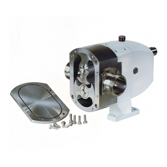
Rotary lobe pump
Hide thumbs
1
Table Of Contents
2
3
4
5
6
7
8
9
10
11
12
13
14
15
16
17
18
19
20
21
22
23
24
25
26
27
28
29
30
31
32
33
34
35
36
37
38
39
40
41
42
43
44
45
46
47
48
49
50
51
52
page
of
52
Go
/
52
Contents
Table of Contents
Bookmarks
Table of Contents
Table of Contents
Introduction
Safety
Principle of Operation
Operating Conditions
Model Numbering System
Inspection Upon Receipt
Installation
Operating Limitations
Location & Positioning
Drives
Baseplate
Guards and Safety
Electrical
Pipework
Enlarged Rectangular Inlet
Temperature Control Jackets
Seals and Flushing
Seal Materials
End Cover Relief Valve
End Cover Barrier
Overload Protection
Lubrication
Start up & Routine Checks
Start up
Daily Checks
Weekly Checks
Monthly Checks
Six Monthly Checks
Annual Checks
Sterilizing in Place (SIP)
Inspection and Repair
End Cover
Rotors
Mechanical Shaft Seals - Double
Seal Housings
Single O-Ring Seal
Double O-Ring Seal
Multi-Lip Seal
Rotor Case
Rotor Clearance - Checking & Adjustment
End Cover Relief Valve
Thermal Jacket -End Cover
Thermal Jacket -Pump Head
Thermal Jacket -Rotor Case
Gearbox Shafts and Gears
Bearing Set-Up and Pre-Load
Model Number Build Code
8 Parts List and Exploded
Parts List
Hy~Line Exploded Diagram
Ultima Exploded Diagram
Hy~Line 3 Size Sectional View
Options & Extras - Sectional Views
Advertisement
Quick Links
1
Lubrication
2
Parts List
3
Hy~Line Exploded Diagram
Download this manual
Hy~Line and Ultima Lobe Pumps
07/03
Installation, Operating, Maintenance and
Spares Manual
Hy~Line
Ultima
&
Rotary Lobe Pump
Rotary Lobe Pump
Table of
Contents
Previous
Page
Next
Page
1
2
3
4
5
Advertisement
Table of Contents
Need help?
Do you have a question about the Hy-Line and is the answer not in the manual?
Ask a question
Questions and answers
Related Manuals for JABSCO Hy-Line
Water Pump JABSCO HD Series Instruction Manual
Pressure system pumps, washdown & water (33 pages)
Water Pump JABSCO 37202-Series Manual
Electric bilge pumps (2 pages)
Water Pump JABSCO 37202-2712 Manual
Bilge pump (2 pages)
Water Pump JABSCO 18590 Series Manual
Self-priming macerator pump (4 pages)
Water Pump JABSCO CENTRI PUPPY 18510-000 Series Manual
Bronze centrifugal dc motor/pump unit with lip seal (4 pages)
Water Pump JABSCO 37202-2712 Quick Start Manual
(2 pages)
Water Pump JABSCO 31395-0092 Instruction Manual
31295 / 31395 - series automatic water system pump (5 pages)
Water Pump JABSCO xylem Operating And Installation Instructions
Flexible impeller pump (16 pages)
Water Pump JABSCO 18220 Series Manual
(4 pages)
Water Pump JABSCO 6400 Series Manual
Self-priming pumps (4 pages)
Water Pump JABSCO 37202-2 Quick Start Manual
Shower drain and bilge pump (14 pages)
Water Pump JABSCO 28 Series Manual
Flexible impeller pump cart system (2 pages)
Water Pump JABSCO 36680-2 Series Manual
Electric bilge pumps (15 pages)
Water Pump JABSCO 50840 Series Manual
Low pressure centrifugal pump (4 pages)
This manual is also suitable for:
Ultima
Table of Contents
Save PDF
Print
Rename the bookmark
Delete bookmark?
Delete from my manuals?
Login
Sign In
OR
Sign in with Facebook
Sign in with Google
Upload manual
Upload from disk
Upload from URL


Need help?
Do you have a question about the Hy-Line and is the answer not in the manual?
Questions and answers