Table of Contents
Advertisement
Quick Links
Backbox Mounting
View Shown with Hole Plug Installed.
Open Faceplate then Remove Nut from the Inside.
1.969 [50.0]
11/32" or 9mm Socket & Socket Wrench
6.212 [157.8]
2.362 [60.0]
4.026 [102.3]
1.969 [50.0]
2.165 [55.0]
Ø0.41 [Ø10.5]
Install a Shunt on JP2 to Enable Auto Answer Mode
Shunt
© 2020, CyberData Corporation, ALL RIGHTS RESERVED
Tool Required to Remove Hole Plug:
14.173 [360.0]
Conduit Hole
Ø1.3 [Ø33]
Conduit Hole Ø 1.3 [Ø33] Fits 1" EMT Fittings
19.685 [500.0]
Dimensions are in Inches [Millimeter]
Last Updated 08/06/2020
JP2
931350C
The IP Endpoint Company
Getting Started
Take the following into consideration before you install this product:
•
When this secure phone case is used, the touch screen capability of the DX phone is disabled.
•
Due to the size and mass of this product, it is important that the Backbox is safely installed according to these installation
instructions.
•
Make sure that the type of wall is capable of supporting the system and use screws that are suitable for that type of wall.
•
The system must be installed by qualified personnel in accordance with state and local building regulations.
•
Also see the
•
Locate the provided Security Torx Driver Bit (usually taped right next to the Hookswitch on the Faceplate).
•
Tool required to remove Security Torx Screws (an Electric Hand Drill or Powered Screwdriver)
•
WARNING: To prevent injury, this apparatus must be securely attached to the floor/wall in accordance with the installation
instructions.
•
WARNING: The PoE connector is intended for intra-building connections only and does not route to the outside plant.
•
WARNING: This enclosure is not rated for any AC voltages!
Hookswitch Wires to USB to Analog Audio Module Connections
Magnetic Hookswitch
Connections
***
Reconnect Before Fasten Faceplate Assembly to Backbox
Contacting CyberData
Corporate Headquarters
CyberData Corporation
3 Justin Court
Monterey, CA 93940, USA
Phone: 831-373-2601
Fax: 831-373-4193
http://www.cyberdata.net/
Quick Reference
Quick Reference
Installation Quick Reference
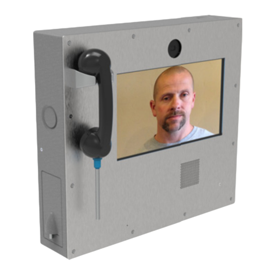
DX70 Secure Phone
011388
(on the other page).
USB to Analog
Audio Module
Terminal
1
***
Block
Black Wires
Red Wire
to Terminal 5
Black Wire
Connector
to Terminal
Receptacle
Connector
Factory Disconnected
Plug
Sales: 831-373-2601 ext. 334
Support: 831-373-2601 ext. 333
Support Website:
http://support.cyberdata.net/
RMA Department: 831-373-2601 ext. 136
RMA Email: RMA@CyberData.net
RMA Status:
http://support.cyberdata.net/
Warranty Information:
http://support.cyberdata.net/
931350C
Backbox
Armored Cord Handset
Connections
Black Wire to Terminal
4
Green Wire to Terminal
3
10
Yellow Wire to Terminal
2
Red Wire to Termianl
1
Armored Cord
USB-B
Armored Cord
USB-A
9
Handset Retainer
Phone
USB-B to USB-A
Cable Connections
© 2020, CyberData Corporation, ALL RIGHTS RESERVED
Advertisement
Table of Contents

Related Manuals for CyberData Cisco DX70


Summary of Contents for CyberData Cisco DX70
- Page 1 Shunt RMA Department: 831-373-2601 ext. 136 RMA Email: RMA@CyberData.net Phone: 831-373-2601 Fax: 831-373-4193 RMA Status: http://support.cyberdata.net/ http://www.cyberdata.net/ Warranty Information: http://support.cyberdata.net/ © 2020, CyberData Corporation, ALL RIGHTS RESERVED 931350C Quick Reference Quick Reference 931350C © 2020, CyberData Corporation, ALL RIGHTS RESERVED...
- Page 2 Use a Paper Clip Through Hole Cover Hole with Provided Foot Stand Torx Button Socket Cap Screw & T15 Torx Driver Bit © 2020, CyberData Corporation, ALL RIGHTS RESERVED 931350C Quick Reference Quick Reference 931350C © 2020, CyberData Corporation, ALL RIGHTS RESERVED...
Need help?
Do you have a question about the Cisco DX70 and is the answer not in the manual?
Questions and answers