
Related Manuals for Belden Grass Valley DENSITE 3+ FR1


Summary of Contents for Belden Grass Valley DENSITE 3+ FR1
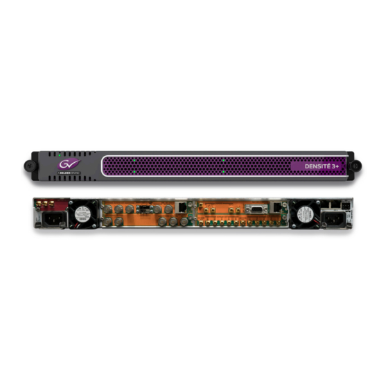
- Page 1 DENSITÉ 3+ FR1 1RU Housing Frame for Densité Modular Products User Manual M969-9900-103 2016-11-28...
- Page 2 Copyright and Trademark Notice Copyright © 2012–2016, Grass Valley Canada. All rights reserved. Belden, Belden Sending All The Right Signals, and the Belden logo are trademarks or registered trademarks of Belden Inc. or its affiliated companies in the United States and other jurisdictions.
- Page 3 Densité 3+ FR1 User Manual Important Safeguards and Notices This section provides important safety guidelines for operators and service personnel. Specific warnings and cautions appear throughout the manual where they apply. Please read and follow this important information, especially those instructions related to the risk of electric shock or injury to persons.
- Page 4 Notices The presence of this symbol in or on Grass Valley product means that it complies with all applicable European Union (CE) directives. The presence of this symbol in or on Grass Valley product means that it complies with safety of laser product applicable standards. Warnings A warning indicates a possible hazard to personnel, which may cause injury or death.
- Page 5 Densité 3+ FR1 User Manual • When installing this equipment, do not attach the power cord to building surfaces. • Products that have no on/off switch, and use an external power supply must be installed in proximity to a main power outlet that is easily accessible. •...
- Page 6 Notices Mesures de sécurité et avis importants La présente section fournit des consignes de sécurité importantes pour les opérateurs et le personnel de service. Des avertissements ou mises en garde spécifiques figurent dans le manuel, dans les sections où ils s’appliquent. Prenez le temps de bien lire les consignes et assurez-vous de les respecter, en particulier celles qui sont destinées à...
- Page 7 Densité 3+ FR1 User Manual La marque ETL Listed d’Intertek pour le marché Nord-Américain certifie que l’appareil visé a été testé par Intertek et reconnu conforme aux exigences applicables en matière de sécurité électrique en vigueur au Canada et aux États- Unis.
- Page 8 Notices • Après tout travail d’entretien ou de réparation, faites effectuer des contrôles de sécurité par le personnel technique qualifié. Mises en garde Les mises en garde signalent des conditions ou des pratiques susceptibles d’endommager l’équipement. Veuillez vous familiariser avec les mises en garde ci- dessous : •...
- Page 9 Densité 3+ FR1 User Manual • Pour plus de sécurité, vérifiez périodiquement la valeur de résistance du bracelet antistatique. Elle doit se situer entre 1 et 10 mégohms. • Si vous devez mettre une carte de côté, assurez-vous de la ranger dans un sac protecteur antistatique.
- Page 10 Notices Electromagnetic Compatibility This equipment has been tested for verification of compliance with FCC Part 15, Subpart B requirements for class A digital devices. Note: This equipment has been tested and found to comply with the limits for a Class A digital device, pursuant to Part 15 of the FCC rules. These limits are designed to provide reasonable protection against harmful interference when the equipment is operated in a commercial environment.
- Page 11 Densité 3+ FR1 User Manual Environmental Compliance 有毒有害物质或元素 (Toxic or hazardous substances and elements) DENSITÉ 3+ FR1 CHASSIS 铅 汞 镉 六价铬 多溴联苯 多溴二苯 部件名称 Part name (Pb) (Hg) (Cd) (Cr6) (PBB) (PBDE) 电缆及电缆组件 Cables and cable assemblies 电路模块 Circuit modules 组装风扇...
- Page 12 Notices...
-
Page 13: Table Of Contents
Table of Contents 1 Introduction ......... . . 1 The Densité... - Page 14 Table of Contents Data Restoration .............23 Factory Alignment.
-
Page 15: Introduction
Introduction Chapter 1 is an introduction to the Densité 3+ FR1 Housing Frame. Summary Overview ................1 Key Features and Benefits . -
Page 16: Available Options
Introduction Available Options • Hot-swappable power supply, with optional redundant power supply. • Supports full range of interfacing, distribution and monitoring modules. • Can be stacked without additional cooling spaces. • Redundant Ethernet connections. • A fifth slot is reserved for system cards such as REF-1801-FR1 or GPI-1501. Available Options Second power supply for redundant power security. -
Page 17: Densité 3+ Fr1 Housing Frame
Densité 3+ FR1 Housing Frame Chapter 2 describes the Densité 3+ FR1 housing frame and details of its installation. Summary Description ................3 Installation . -
Page 18: Installation
Densité 3+ FR1 Housing Frame Installation • Right side - a second power supply is located on the lower right, and above it is a single slot reserved for System Cards. Note: This slot supports ONLY designated System Cards; do not insert any other cards. At the time of writing, only the REF-1801-FR1 or the GPI-1501 card is supported. -
Page 19: Opening The Front Door
Densité 3+ FR1 User Manual • CPU-ETH2 controller card • Power cord retaining clips (2) • A second power supply and AC cord (optional) • A system card, per order • Densité-series cards (per order) with associated rear panels Opening the Front Door The front door of the Densité... -
Page 20: Using Densité 2 Cards In The Densité 3+ Fr1 Frame
Densité 3+ FR1 Housing Frame Using Densité 2 cards in the Densité 3+ FR1 Frame 3 Position the new panel and secure it in place with the captive screw(s) on the right- hand side. To remove and/or install a card 1 Open the front door of the frame 2 To install a card into an empty slot, slide the card into the slot with the swivel handle to the right, and push gently on the handle to seat the connectors. - Page 21 Densité 3+ FR1 User Manual To install these on the Densité 2 card 1 Fit the top edge of the card into the holding slot along the bottom edge of the adapter. 2 Align the holes in the top of the card with the holes on the adapter, and secure them together with the two provided screws and lock washers, as shown in the figure.
-
Page 22: Installing The Power Cord Retaining Clips
Densité 3+ FR1 Housing Frame Installing the Power Cord Retaining Clips Installing the Power Cord Retaining Clips Each power supply is provided with a power cord retaining clip that holds the power cord in place to prevent inadvertent disconnections. To install the retaining clips 1 With the power cord removed, install the clip into the plate that extends out beneath the power cord socket on the rear of the frame, by slipping the two ends of the clip into a pair... -
Page 23: Field-Serviceable Items
Densité 3+ FR1 User Manual Users who wish to utilize this alarm reporting mechanism should be aware of the circuit driving the GPI connector, in order to correctly interpret its signalling. Field-Serviceable Items Field-serviceable items on the Densité 3+ FR1 frame itself include the power supplies, the controller card, the system card, and the ventilation fans. -
Page 24: Replacing The Controller Card
Densité 3+ FR1 Housing Frame Replacing the Controller Card 3 Remove the power supply module by pulling on the handle on its front panel and sliding it out of the frame 4 Slide the new power supply module into the slot, and push it gently into position to seat the connectors. - Page 25 Densité 3+ FR1 User Manual To replace a frame ventilation fan 1 Procure a replacement fan assembly. It is comprised of a fan and an attached circuit board. It is available from Grass Valley as part #0969-2100. 2 Remove the two screws that secure the fan assembly to the frame and pull the fan assembly straight out of the frame.
-
Page 26: Installing And Replacing The System Card
Densité 3+ FR1 Housing Frame Installing and Replacing the System Card Installing and Replacing the System Card The system card is located in the upper right-hand-side of the Densité 3+ FR1 frame, as seen from the front. The system card is optional, and may be factory-installed when the system is ordered, or installed by the user later. -
Page 27: Cpu-Eth2 Controller Card
CPU-ETH2 Controller Card Chapter 3 describes the installation and functionality of the CPU-ETH2 Controller card in the Densité 3+ FR1 housing frame. Summary Overview ................13 Control Interfaces . -
Page 28: Control Interfaces
CPU-ETH2 Controller Card Control Interfaces • Provides ultra-robust Ethernet connectivity for LAN/WAN • Accelerated data throughput: allows video thumbnail and audio level meter and line scope streaming from all installed modular cards • Linux-based operating system for robust, mission-critical operations •... -
Page 29: Using The Local Control Panel
Densité 3+ FR1 User Manual • CPU-ETH2 controllers are identified as Controller2 in the Type column of the iControl Navigator window. • For convenience, enter a descriptive Label in the Info panel of the card, to make it easy to locate this specific frame controller amongst those in the list. See Identification, on page 19 for instructions. -
Page 30: Card-Front Status Led
CPU-ETH2 Controller Card Card-Front Status LED Pushing the CONTROLLER button on the control panel assigns the panel to operate the CPU-ETH2 card itself. The STATUS LED on the CPU-ETH2 card flashes yellow to show that it is selected for control. The local control panel displays a menu that can be navigated using the four pushbuttons located beside the display. -
Page 31: Configuring The Cpu-Eth2 Controller
Densité 3+ FR1 User Manual Configuring the CPU-ETH2 Controller This section introduces the operating features of the CPU-ETH2 controller, and describes how to access and control them using: • The iControl interface • The local control panel and menu. The local control panel must be used to configure the network settings for the controller. Beyond that, the iControl interface is more comprehensive and easier to use, so it will be used as the primary interface for purposes of describing the configuration process. - Page 32 CPU-ETH2 Controller Card Network Configuration 6 Click [SEL] and [ESC] to select a number, and [+] and [–] to change its value. 7 When done, click [ESC] until the IP ADDRESS menu item appears. 8 Click [–] until NETWORK MASK appears in the display. 9 Repeat step 5 step 7...
-
Page 33: Identification
Densité 3+ FR1 User Manual Changes to these parameters require a controller reboot. Click Reboot... to accept the changes and restart the controller. Click Cancel... to reject the changes and leave the settings unchanged. Using the Menu: To change the IP address:: To enable/disable the Redundancy option, and select the bonding mode: Note that the Host Name and the MAC address are reported in the menu but cannot be changed from there. -
Page 34: Status Monitoring
CPU-ETH2 Controller Card Status Monitoring Three buttons in the panel give access to other information: Details: Reports the Firmware version, service version, and panel version for this card Advanced: Shows the LongID for this card. The LongID is the address of this CPU-ETH2 controller in the iControl network. - Page 35 Densité 3+ FR1 User Manual iControl - click the Status button The iControl interface always displays two icons in the upper left of the window. These report the status of the two power supplies. The graphic shows the possible icon displays and the associated messages that appear below them.
-
Page 36: Snmp Functionality
CPU-ETH2 Controller Card SNMP functionality Status - Cards Select the Cards tab to see a chart of the current send (Tx) and receive (Rx) data rates, and speed, for all cards installed in the Densité frame. Note that in the Densité 3+ FR1 frame, only slots 1 to 4 are available. -
Page 37: Data Restoration
Densité 3+ FR1 User Manual iControl - click the Network button and select the SNMP tab. Click the Activate SNMP Agent box to activate this feature Enter the IP addresses of up to three SNMP trap targets in the boxes provided. Using the Menu: SNMP activation and up to three target IP addresses can be entered in the menu via the SNMP OPTIONS item. - Page 38 CPU-ETH2 Controller Card Data Restoration iControl - click the Restore Point button and view the Cards tab. The tab show a list of the slots available in the Densité frame, with a check box, name, and status box for each. •...
-
Page 39: Factory Alignment
Densité 3+ FR1 User Manual Save: The CPU-ETH2 card can be configured to automatically back up the data on the cards in its slots according to a set schedule. Click the Auto Save box to enable the automatic save function. Set up the schedule for data backup using the controls provided. -
Page 40: Time Management
CPU-ETH2 Controller Card Time Management. Note: Ethernet settings are not included in the Factory data set, and are not changed when the Factory Default alignment is installed. iControl - click the Factory Control button Click the Load Factory button to restore the card to the Factory default alignment. -
Page 41: Alarms
Densité 3+ FR1 User Manual iControl - click the Time button Time (UTC) The data boxes in this section display the time and date currently held in the card. Enter new values in these boxes to change the current setting. If an automatic update via NTP is not enabled, the clock will continue to run using an on- board reference, but precision is not... - Page 42 CPU-ETH2 Controller Card Alarms GPI reporting can only be accessed from the menu, as described at the end of this section (page 32). iControl - click the Alarm Config button The iControl Alarm Configuration panel opens in a new window when the Alarm Config button is clicked, and can be resized if needed.
- Page 43 Densité 3+ FR1 User Manual Levels associated with these alarms: The alarm status list may contain some or all of the following options: Alarm status Significance The alarm makes no contribution (black icon) The alarm is of minor importance (yellow icon) The alarm is of major importance (orange icon) The alarm is of critical importance (red icon) The alarm exists but has no effect (used for text and composite alarms)
-
Page 44: Options
CPU-ETH2 Controller Card Options Get alarm keys Click this button to open a save dialog where you can save a file containing a list of all alarms on this controller and their current values, along with an Alarm Key for each. The alarm keys are useful for system integration and troubleshooting. - Page 45 Densité 3+ FR1 User Manual Active-Backup: This mode provides fault tolerance. Transmissions are received and sent out via the first available bonded slave interface. Another bonded slave interface is only used if the active bonded slave interface fails. This mode doesn't require any configuration of the remote equipment.
-
Page 46: Local Control Panel Menu
CPU-ETH2 Controller Card Local Control Panel Menu Local Control Panel Menu Here is the complete on-board menu for the CPU-ETH2 controller, accessed through its local control panel. continued... - Page 47 Densité 3+ FR1 User Manual Local Control Panel Menu continued.
- Page 48 CPU-ETH2 Controller Card Local Control Panel Menu...
-
Page 49: Ref-1801-Fr1 Frame Reference
REF-1801-FR1 Frame Reference Chapter 4 describes the installation and functionality of the REF-1801-FR1 Frame Reference card in the Densité 3+ FR1 frame. Summary Overview ................35 Applications . -
Page 50: Block Diagram
REF-1801-FR1 Frame Reference Block Diagram Block Diagram Fig. 4-1: Functional block diagram Card Front Edge Layout Fig. 4-2: Card edge layout Applications Referencing converters and frame sync modules In this application, the REF-1801-FR1 accepts a reference input and generates a URS4D signal that is distributed to the four slots within the same frame. -
Page 51: Slaving Cards In A Frame To Another Ref-Equipped Frame
Densité 3+ FR1 User Manual Fig. 4-3: Application - referencing converters and frame sync modules Slaving cards in a frame to another REF-equipped frame In this application, the reference signal is distributed in order to slave another Densité frame. The ability to carry time code and SMPTE-318 information will allow the slaved frame to operate with the same A/V phasing information as the master frame. -
Page 52: Installation In The Densité 3+ Fr1 Frame
REF-1801-FR1 Frame Reference Installation in the Densité 3+ FR1 frame Installation in the Densité 3+ FR1 frame The REF-1801-FR1 must be mounted in a Densité 3+ FR1 frame. The installation includes both the REF-1801-FR1 module, and the rear panel module. It is not necessary to switch off the frame’s power when installing or removing the card. -
Page 53: Menu For Local Control
Densité 3+ FR1 User Manual Menu for local control The REF-1801-FR1 has operating parameters which may be adjusted locally at the controller card interface. After pressing the Select button on the REF-1801-FR1 module, use the keys on the local control panel to step through the displayed menu and adjust the parameters. -
Page 54: The Icontrol Graphic Interface Window
REF-1801-FR1 Frame Reference The iControl graphic interface window • Please consult the iControl User’s Guide for information about setting up and operating iControl. In iControl Navigator or iControl Websites, double-click on the REF-1801-FR1 icon to open the control panel. NOTE: REF-1801 is the “short label” for a REF-1801-FR1 inside iControl. The iControl graphic interface window The basic window structure for the REF-1801 is shown in figure 3. -
Page 55: Input Tab
Densité 3+ FR1 User Manual • Hovering the cursor over the Reference Status icon will show the format of the input reference Icon # Indicates Appearance Interpretation Card control Green if the card is controlled remotely. status Yellow when locally controlled. Input reference Green if OK. - Page 56 REF-1801-FR1 Frame Reference Input tab To select the reference source for this REF-1801-FR1 Use the pulldown to select the reference source: • Auto – Use the external reference if available; switch to the internal reference if the external reference is lost or unavailable. •...
-
Page 57: Mode Tab
Densité 3+ FR1 User Manual Mode tab Click the Mode tab. Fig. 4-8: Mode tab URS (Universal Reference Signal) is a Grass Valley proprietary reference that is used within a Densité frame. It is generated by the REF-1801-FR1 (which must be located in slot 5), and distributed to other cards in the frame via the frame’s midplane. -
Page 58: Alarms Tab
REF-1801-FR1 Frame Reference Alarms tab Alarms tab Click the Alarms tab Fig. 4-9: Alarms tab Timecode logging Select a checkbox to send the indicated time code to the iControl GSM, where it can be used by other network devices. • As this uses network resources, it is suggested that these boxes be left unchecked if there is no need to use the time code in this way. - Page 59 Densité 3+ FR1 User Manual Status/Name This contains an expandable tree listing all the alarms reported by this card. Each alarm name includes an icon that shows its current status The Overall alarm and GSM contribution columns contain pulldown lists that allow the level of contribution of each individual alarm to the alarm named in the column heading to be set.
- Page 60 REF-1801-FR1 Frame Reference Alarms tab Fig. 4-11: Alarm configuration - Copy to other cards To copy the alarm configuration 1 Select one or more destination cards from the list in the window by clicking in the checkboxes, or all of them by clicking in the All checkbox. 2 Click Copy The status of the transfers for each destination card is shown in the Transfer Status column.
-
Page 61: Info Tab
Densité 3+ FR1 User Manual Info tab When the REF-1801 is included in an iControl environment, certain information about the card should be available to the iControl system. The user can enter labels and comments that will make this card easy to identify in a complex setup. This information is entered into data boxes in the Info panel. - Page 62 REF-1801-FR1 Frame Reference Info tab • Remote System Administration...: Opens the Joining Locators window, which lists remote lookup services to which this REF-1801 is registered. Add: Force the iControl service for this REF-1801 to register itself on a user-specified Jini lookup service, using the following syntax for the locator’s URL in the Input data box: jini://<ip_address>...
-
Page 63: Specifications
Densité 3+ FR1 User Manual Specifications GENLOCK INPUT CONNECTOR DIN 1.0/2.3 LOAD Passive Loop-Through IMPEDANCE 75 Ohm bridging RETURN LOSS > 30 dB up to 30 MHz FREQUENCY LOCK RANGE compliant with RS-170M > 40 dB SIGNAL TYPE Composite NTSC-M, PAL-B Black Burst with optional VITC STANDARD SMPTE-170M, ITU-R BT.1700-1, SMPTE-318M SIGNAL LEVEL... - Page 64 REF-1801-FR1 Frame Reference Specifications...
-
Page 65: Contact Us
Contact Us Grass Valley Technical Support For technical assistance, contact our international support center, at 1-800-547-8949 (US and Canada) or +1 530 478 4148. To obtain a local phone number for the support center nearest you, please consult the Contact Us section of Grass Valley’s website ( www.grassvalley.com An online form for e-mail contact is also available from the website.
Need help?
Do you have a question about the Grass Valley DENSITE 3+ FR1 and is the answer not in the manual?
Questions and answers