Table of Contents
Advertisement
Quick Links
Advertisement
Table of Contents

Related Manuals for Belden GRASS VALLEY DENSITÉ 3+ FR4


Summary of Contents for Belden GRASS VALLEY DENSITÉ 3+ FR4
- Page 1 DENSITÉ 3+ FR4 HOUSING FRAME User Manual M3007-9900-102 2016-06-22...
- Page 2 Copyright and Trademark Notice Copyright © 2015-2016, Grass Valley Canada. All rights reserved. Belden, Belden Sending All The Right Signals, and the Belden logo are trademarks or registered trademarks of Belden Inc. or its affiliated companies in the United States and other jurisdictions.
- Page 3 Densité 3+ FR4 User Manual Important Safeguards and Notices Symbols and Their Meanings ............iii Warnings .
- Page 4 Notices The presence of this symbol in or on Grass Valley equipment means that it has been tested and certified as complying with applicable Intertek Testing Services regulations and recommendations for USA/Canada. The presence of this symbol in or on Grass Valley product means that it complies with all applicable European Union (CE) directives.
- Page 5 Densité 3+ FR4 User Manual Cautions A caution indicates a possible hazard to equipment that could result in equipment damage. Observe the following cautions when operating or working on this equipment: • This equipment is meant to be installed in a restricted access location. •...
- Page 6 Notices Mises en gardeLes mises en garde signalent des conditions ou des pratiques susceptibles d’endommager l’équipement. Veuillez vous familiariser avec les mises en garde ci-dessous : viiiLa présente section fournit des consignes de sécurité importantes pour les opérateurs et le personnel de service. Des avertissements ou mises en garde spécifiques figurent dans le manuel, dans les sections où...
- Page 7 Densité 3+ FR4 User Manual La marque ETL Listed d’Intertek pour le marché Nord-Américain certifie que l’appareil visé a été testé par Intertek et reconnu conforme aux exigences applicables en matière de sécurité électrique en vigueur au Canada et aux États- Unis.
- Page 8 Notices • Après tout travail d’entretien ou de réparation, faites effectuer des contrôles de sécurité par le personnel technique qualifié. Mises en garde Les mises en garde signalent des conditions ou des pratiques susceptibles d’endommager l’équipement. Veuillez vous familiariser avec les mises en garde ci-dessous : •...
- Page 9 Densité 3+ FR4 User Manual • Les cartes qui sont reliées à un châssis ou boîtier métallique mis à la terre ne nécessitent pas de protection antistatique spéciale. Recycling Visit www.grassvalley.com for recycling information. Certification and Compliance Safety Compliance This equipment complies with the requirements of CSA/UL/IEC/EN 60950-1, 2 Ed.
- Page 10 Notices Electromagnetic Compatibility This equipment has been tested for verification of compliance with FCC Part 15, Subpart B requirements for class A digital devices. Note: This equipment has been tested and found to comply with the limits for a Class A digital device, pursuant to Part 15 of the FCC rules. These limits are designed to provide reasonable protection against harmful interference when the equipment is operated in a commercial environment.
-
Page 11: Table Of Contents
Table of Contents 1 Introduction ......... . . 1 The Densité... - Page 12 Table of Contents Factory Settings .............39 Upgrading the Frame Reference .
-
Page 13: Introduction
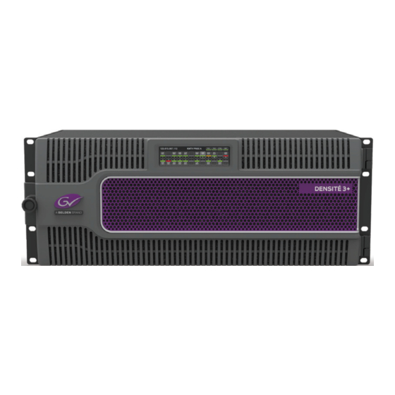
The Densité 3+ FR4 Frame Overview - Frame The 4 RU Densite 3+ FR4 Frame from Grass Valley, a Belden Brand, is a modular frame and controller designed to deliver more power per slot and higher speed connectivity needed by the increased feature set of the latest Densité... -
Page 14: Overview - Controller
Introduction Key Product Capabilities • Fully backwards compatible with Densité 2 and Densité 3 cards. • 24 slots with a power budget of 25 watts per slots. • Optional frame reference on controller card. • Fully modular I/O for the frame controller for “future readiness” of the controller I/O. •... -
Page 15: Description
Densité 3+ FR4 User Manual Features • Dual Ethernet RJ-45 ports (100Base-T and Gigabit Ethernet) - the two ports can be config- ured independently for full network redundancy • Provides ultra-robust Ethernet connectivity for LAN/WAN • Accelerated data throughput: allows video thumbnail and audio level meter and line scope streaming from all installed modular cards •... - Page 16 Introduction Front of the frame When the frame door is closed, the controller card touch screen is exposed through an opening in the top center of the door. All other front elements are concealed by the door. Rear of the Frame The rear of the Densité...
-
Page 17: Controller Rear Panel
Densité 3+ FR4 User Manual Controller Rear Panel The rear panel associated with the frame’s controller card is located at the top center of the frame. All inputs and outputs to the controller from outside the frame are connected through this panel. -
Page 18: Specifications
Introduction Specifications Users who wish to utilize this alarm reporting mech- anism should be aware of the circuit driving the GPI connector, in order to correctly interpret its signalling. Specifications MECHANICAL Dimensions 4RU x 19” W (485 mm) x 11.25” D (286 mm) with connectors Weight: 7.16 lbs (3,25 kg) with 1 PSU and controller card installed POWER... -
Page 19: Installation
Installation Summary Unpacking ................7 Opening the Front Door . -
Page 20: Mounting
Installation Mounting Mounting The Densité 3+ FR4 housing frame occupies 4RU in a standard 19” rack. To mount the frame • Remove the front door to expose the rack mounting flanges at the ends of the chassis. • Install the frame in the rack using 8 standard rack-mounting screws (not supplied) through the eight holes in the mounting flanges. -
Page 21: Using Densité 2 Cards In The Densité 3+ Fr4 Frame
Densité 3+ FR4 User Manual Card Installation and removal 1 Open the front door of the frame 2 To install a card into an empty slot, slide the card into the slot with the swivel handle to the top, and push gently on the handle to seat the connectors. If the card requires a double- width rear panel or larger to accommodate a large number of connectors, it should be inserted into the right-hand slot. - Page 22 Installation Mounting Card adapters: There are 3 different types of adapters that can be used, depending on the Densité 2 card geometry: o DENSITE 3-EXT-A o DENSITE 3-EXT-B o DENSITE 3-EXT-C Install these on the Densité 2 card as follows: 1 Fit the top edge of the card into the holding slot along the bottom edge of the adapter.
-
Page 23: Installing The Power Cord Retaining Clips
Densité 3+ FR4 User Manual Installing the Power Cord Retaining Clips Each power supply is provided with a power cord retaining clip that holds the power cord in place to prevent inadver- tent disconnections. To install the power cord retaining clips 1 With the power cord removed, install the clip into the plate that extends out beneath the power cord socket on the rear of the frame, by slipping the two... - Page 24 Installation Ventilation...
-
Page 25: Configuration
Configuration Summary Using the Ethernet interface ............13 Using the local control interface . - Page 26 Configuration In iControl Navigator or iControl Websites, double-click on the icon of the controller to open its control panel. • CPU-ETH3 controllers are identified as Controller3 in the Type column of the iControl Navigator window. • For convenience, enter a descrip- tive Label in the Info panel of the card, to make it easy to locate this specific frame controller amongst...
-
Page 27: Using The Local Control Interface
Densité 3+ FR4 User Manual Using the local control interface The local control interface is fastened to the front of the CPU-ETH3 controller card, and when installed is located in the top center of the frame. The touch screen interface is accessed through an aperture in the frame door. In its home state, it shows the contents of all 24 slots in the Densité... -
Page 28: Using The Controller's Web Page
Configuration Pushing [ESC] moves the user back up to the previous menu level. [HOME] Exits the current menu and returns the user to the HOME screen. If no controls are operated for 30 seconds, the controller reverts to its normal operating status, and the status display ceases flashing yellow and reverts to its normal operating mode. -
Page 29: Configuring The Cpu-Eth3 Controller
Densité 3+ FR4 User Manual 2 Select the topic area of interest from the index on the left, and click to open the configuration page. Configuring the CPU-ETH3 Controller This section introduces the operating features of the CPU-ETH3 controller, and describes how to access and control them using: •... -
Page 30: Identification
Configuration Identification iControl - click the Info button The CPU-ETH3 controller is accessible on a network, and must be identifiable in order to function in the iControl environment. The identification data is entered in the iControl INFO control panel. This panel also shows other data that is not user-adjustable. -
Page 31: Status Monitoring
Densité 3+ FR4 User Manual Remove: select one of the services listed in the window by clicking on it, and click Remove to open a query box allowing you to delete it from the window. Using the menu None of this data can be accessed via the local control panel menu, except to read the Firmware version. - Page 32 Configuration iControl - click the Status button Status - Frame Select the Frame tab to see a report on the status of the frame’s CPU, fans and power supplies. Status - Network Select the Network tab to see a report on the status of the two Ethernet ports on the CPU- ETH3 card.
- Page 33 Densité 3+ FR4 User Manual Status - Cards Select the Cards tab to see a chart of the current send (Tx) and receive (Rx) data rates, and speed, for all cards installed in the Densité frame. For a more detailed report on the status of a specific card, open that card’s control panel in iControl.
-
Page 34: Network
Configuration Network iControl - click the Network button and select the ETH tab Enter the HOSTNAME in the box at the top. • The hostname is the unique name by which this Densité CPU-ETH3 is known on the network. The hostname should be 15 characters or less, and may contain only the ASCII letters 'a' through 'z' (case-insen- sitive), the digits '0' through '9' , and the... -
Page 35: Data Restoration
Densité 3+ FR4 User Manual • Channel bonding is an arrangement in which the CPU-ETH3’s two network interfaces are combined for redundancy. The Densite 3+ CPU-ETH3 works in the Active-Backup bonding mode. Active-Backup bonding provides fault tolerance. • Only one slave in the bond is active. •... - Page 36 Configuration For manual operation: iControl - click the Restore Point button and view the Cards tab. The tab show a list of the slots available in the Densité frame, with a check box, name, and status box for each. Click the check box to activate the Data Restore feature for the card in that slot, -or- Click the Select All box at the top to activate...
-
Page 37: Factory Alignment
Densité 3+ FR4 User Manual Save: The CPU-ETH3 card can be configured to automatically back up the data on the cards in its slots according to a set schedule. Click the Auto Save box to enable the auto- matic save function. Set up the schedule for data backup using the controls provided. -
Page 38: Time Management
Configuration alignment in its memory, to which it can be restored at any time. Note: Ethernet settings are not included in the Factory data set, and are not changed when the Factory Default alignment is installed. iControl - click the Factory Control button Click the Load Factory button to restore the card to the Factory default alignment. -
Page 39: Alarms
Densité 3+ FR4 User Manual iControl - click the Time button Time (UTC) The data boxes in this section display the time and date currently held in the card. Enter new values in these boxes to change the current setting. If an automatic update via NTP is not enabled, the clock will continue to run using an on-board reference, but preci- sion is not guaranteed. - Page 40 Configuration iControl - click the Alarm Config button The iControl Alarm Configuration panel opens in a new window when the Alarm Config button is clicked, and can be resized if needed. It allows the alarm reporting of the CPU-ETH3 to be configured.
- Page 41 Densité 3+ FR4 User Manual The alarm status list may contain some or all of the following options: Alarm status Significance The alarm makes no contribution (black icon) The alarm is of minor importance (yellow icon) The alarm is of major importance (orange icon) The alarm is of critical importance (red icon) The alarm exists but has no effect (used for text and composite alarms) Shortcut: if you click on “Set All”...
- Page 42 Configuration Get alarm keys Click this button to open a save dialog where you can save a file containing a list of all alarms on this controller and their current values, along with an Alarm Key for each. The alarm keys are useful for system integration and troubleshooting.
-
Page 43: Local Control Panel Menu - Cpu-Eth3
Densité 3+ FR4 User Manual Local Control Panel Menu - CPU-ETH3 Here is the complete on-board menu for the CPU-ETH3 controller, accessed through its local control panel. (continued) -
Page 44: Upgrading The Cpu-Eth3 Controller
Configuration Upgrading the CPU-ETH3 Controller Upgrading the CPU-ETH3 firmware must be accomplished via a web page served by the controller, and accessed through its ethernet port using a browser. To upgrade the CPU-ETH3 controller 1 Obtain an upgrade file from Grass Valley. The file will be named 3034-01P80-###_CPU-ETH3-BASIC-Firmware_v#.#.#.zip, where ### is the firmware release version number. -
Page 45: Configuring The Frame Reference
Densité 3+ FR4 User Manual The current firmware version is shown at the top of the window 6 Click Choose File. 7 In the Open window, browse to the upgrade file you obtained in Step 1, select it and click Open. In the Tools | Upgrade Frame Controller window, the upgrade firmware version will be shown at the top of the page, and the Upgrade button will be enabled. -
Page 46: Reference Source
Configuration • The frame reference distributes a Universal Reference Signal (URS) to all modular cards in the frame. • If the option has not been purchased, individual modular cards in the frame must be connected to their own reference signals via their rear panels. To open the Frame Reference control panel Double-click on the Frame Reference icon In iControl Navigator to open the service panel. -
Page 47: Timecode
Densité 3+ FR4 User Manual 3 Click to select the URS Generation mode: Mode Means Normal The URS frame rate matches the selected reference input, i.e. only 29.97 or 25 Hz. Free Run All URS synchronization signals are generated, even the frame-rate- mismatched ones. -
Page 48: Alarms
Configuration The current status of timecode available to the reference module is shown in the LTC Status and VITC Status areas: Status Icon Details Valid Green Valid timecode detected at the input. SMPTE-12 specifies the phase relation between LTC and Phase Error Red video. -
Page 49: Information
Densité 3+ FR4 User Manual 3 For each line in the Status/Name column: a Click on the icon in the Overall Alarm column. b Click to select the appropriate alarm status from the drop-down list. c Click on the icon in the GSM Contribution column. d Click to select the appropriate alarm status from the drop-down list. - Page 50 Configuration 2 Enter appropriate text in the white data boxes (the image shows the default values): Data Usage The label that is shown for this card in iControl applications. Label short-form label that iControl uses in some cases (8 characters). Short Label The Source ID A descriptive name for this frame reference.
-
Page 51: Factory Settings
Densité 3+ FR4 User Manual Button Shows the LongID for this device. The LongID is the address of Advanced... this frame reference in the iControl network. Remote System Opens the Joining Locators window, which lists remote lookup Administration services to which this frame reference is registered. To add additional services 1 Click Add 2 Enter the IP address of a server running a Jini look-up... -
Page 52: Upgrading The Frame Reference
Configuration Upgrading the Frame Reference The Frame Reference is upgraded using the Densité Upgrade Manager. See your iControl documentation for detailed instructions. -
Page 53: Service And Maintenance
Service and Maintenance Summary Changing the Power Supply ............41 Replacing the Controller . -
Page 54: Replacing The Controller
Service and Maintenance Field-Serviceable Items To install or change a power supply module: 1 Open the front door of the frame 2 Lift up the latching tab in the front center of the supply. 3 Slide the power supply out of the frame by pulling on the bracket on the bottom right of the supply. -
Page 55: Replacing The Frame Ventilation Fans
Densité 3+ FR4 User Manual 5 With the lever extended, slide the new controller gently into the controller slot as far as you can until it stops. Do not apply any force, as it may damage the controller/display interface. 6 Firmly push the lever up to seat the card in its connectors. 7 Close the front door of the frame Replacing the Frame Ventilation Fans In case of failure of one of the two cooling fans assemblies on the rear of the frame, replace it... -
Page 56: Cleaning And Replacing The Front-Door Air Filter
Service and Maintenance Field-Serviceable Items • Use the two screws that were retained when the old fan assembly was removed to secure the new fan assembly to the rear panel. Cleaning and replacing the front-door air filter Cooling air pulled into the frame by the rear fan assemblies passes throught an air filter located in the front door of the frame. - Page 57 Densité 3+ FR4 User Manual To install the filter in the door 1 Orient the filter so the cutout for the controller display window lines up with the window in the frame door. 2 Slip the holes in the four corners of the filter over the hooks on the door panel. 3 Insert the tip of the retaining bar into the slot on the hinge end of the door 4 Tighten the thumbscrew on the other end of the retaining bar to hold it in place.
- Page 58 Service and Maintenance Field-Serviceable Items...
-
Page 59: Contact Us
Contact Us Grass Valley Technical Support For technical assistance, contact our international support center, at 1-800-547-8949 (US and Canada) or +1 530 478 4148. To obtain a local phone number for the support center nearest you, please consult the Contact Us section of Grass Valley’s website ( www.grassvalley.com An online form for e-mail contact is also available from the website.
Need help?
Do you have a question about the GRASS VALLEY DENSITÉ 3+ FR4 and is the answer not in the manual?
Questions and answers