
Related Manuals for bar agturn PKT Series

Summary of Contents for bar agturn PKT Series
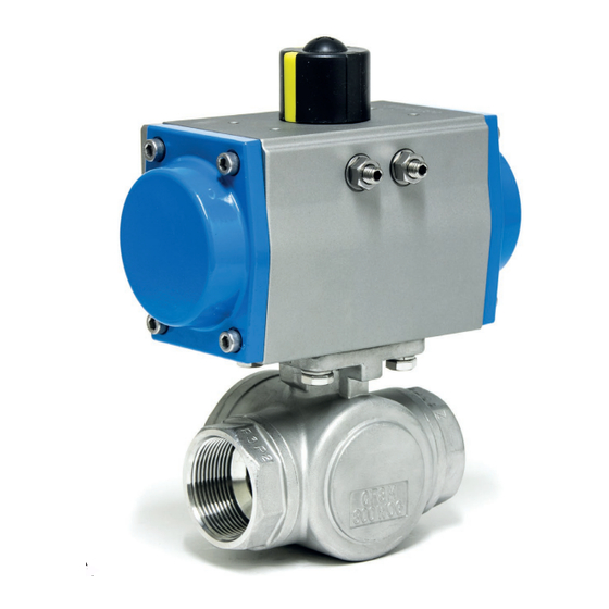
- Page 1 3/2-way automatic valve of PKT type Translation of the original operating manual bar-gmbh.de...
-
Page 2: Table Of Contents
Table of Contents General information ..............5 Reference documents ..................5 Validity of the operating manual .................5 Notes to operating manual .................5 1.3.1 Signal words and symbols ..............5 1.3.2 Explanation of the structure of the safety instructions ......7 1.3.3 Descriptions in figures ................7 Responsibility of the operating company ............7 Safety .................. - Page 3 Rotary actuator bar-agturn ................19 3.3.1 Overview of different models ..............19 3.3.2 Functional description ................20 3.3.3 Operating and display elements ............22 3.3.4 Accessories .................... 22 Transport and storage .............23 Scope of delivery ....................23 4.1.1 Incoming goods inspection ..............23 Transport, packaging and storage ..............
- Page 4 14.4.1 Dimensional drawing 3/2-way automatic valve of PKT type ....42 14.4.2 Dimensional table for 3/2-way automatic valve of PKT type ....44 14.5 Actuator assignment ..................46 14.6 Weight and volume of the rotary actuators bar-agturn ........47 14.7 Switching positions of ball valve ..............48 PKT-GD/GS-IM-DE-B-EN-09-19 Rev.0...
-
Page 5: General Information
The instructions information – also in other language ver- must therefore be observed. sions, can be obtained from: 1.3.1 Signal words and symbols bar pneumatische Steuerungssysteme GmbH DANGER Auf der Hohl 1 ... indicates a hazard that, if not avoided, 53547 Dattenberg will result in death or serious injury. - Page 6 Hand injuries! NOTE The text passages marked with ... indicates important information (e.g. this symbol inform you about Material damage) but not hazards. dangerous situations resulting in hand injuries caused by bruising or punching. The activities described in the relevant Electric voltage! text passage must be performed with the The text passages marked with...
-
Page 7: Explanation Of The Structure Of The Safety Instructions
1.3.2 Explanation of the structure of Responsibility of the the safety instructions operating company A safety instruction is initiated with a signal • The installation, electrical and pneumatic connection as well as the commission- word describing the severity of the danger ing of the product may only be carried ( „Chapter 1.3.1 Signal words and symbols“... -
Page 8: Safety
Please note that only original spare and sheet must be observed. wear parts of bar GmbH are to be used. • Intended use also includes the obser- vance of these operating instructions. -
Page 9: Personnel Qualification
Personnel qualification Use head protection! Wear suitable head protection Only trained or instructed personnel who during transport. has known and understood the operating instructions as well as the possible dangers of the rotary actuator is allowed to work with Use protective clothing! the rotary actuator. -
Page 10: Dangers When Dealing With The Automatic Valve
Dangers when dealing with the automatic valve This product of bar GmbH is built according to the state of the art and the recognized safety rules. Nevertheless, there remains a residual risk and may cause dangers to the life and limb of the user or third parties or impairments of the product and other material assets in use, if: •... -
Page 11: Dangers During Assembly, Maintenance And Disassembly
2.7.1 Dangers during assembly, WARNING maintenance and disassembly Very cold and hot surfaces! DANGER The body of the valve can be- come very cold or very hot Electric voltage! during operation. There is danger to life when work- ing on electrical components. •... - Page 12 WARNING WARNING Danger of crushing hands Flying parts! and other body parts! Splashing medium! There is a risk of injury during as- There is a risk of injury when the valve is sembly/disassembly by movements of the removed under pressure or with present ball.
-
Page 13: Dangers During Functional Checks, Commissioning And Operation
2.7.2 Dangers during functional WARNING checks, commissioning and operation Uncontrolled start-ups! There is a risk of injury if pneumatic rotary DANGER actuators create a very high torque during actuation or by spring force. Bursting parts! • Escaping media! Secure the rotary actuator against any unintentional start-up or unexpected There is danger to life if the maximum per- spinning. - Page 14 WARNING WARNING Danger of being pulled in, Risk of burns! danger of crushing and Devices and system components locking can become very hot during op- eration. Danger due to moving parts of the ma- • Wear protective gloves and protective chine/valve which can be accessed clothing to protect against burns.
-
Page 15: Dangers When Used In Explosion-Protected Areas
2.7.3 Dangers when used in CAUTION explosion-protected areas Self-loosing components! DANGER Components and fasteners may become loose if not properly installed. Danger of explosion! • Observe the information on tightening An explosion can occur if the following torques in this operating manual. protective measures are not observed: •... - Page 16 DANGER Danger of explosion (continuation) • Always observe the max. permissible operating pressure. Exceeding can cause material failure which can lead to sparking. • Avoid dust accumulation. • Do not install rotary actuators in pit- like cavities if there is a predictable dust accumulation.
-
Page 17: Product Description
4-fold bearing of the ball in the half-shells ball • Optionally available with end position • Rotary actuator bar-agturn, types GD- feedback, position controllers and sole- 032 to 040, GD/GS-052 to 400 noid valves The valve is operated pneumatically (dou- •... -
Page 18: Type Plate
PKT-2/0-T2-038-GD105 Article/order designation (see data sheet) PN 50 Maximum permissible medium pressure P (St)= 3-8 bar Control pressure range for the pneum. rotary actuator Ex II 2 GD c 26/07/19 ATEX marking and date of manufacture (year of construc- tion) Ball valve The 3/2-way ball valve of KT type is intended for installation in piping systems. -
Page 19: Rotary Actuator Bar-Agturn
Rotary actuator bar-agturn 3.3.1 Overview of different models Fig. 3-2 Product variants bar-agturn GD-032 till 040, GD/GS-052 till 270, GD/GS-300 till 400 Fig. 3-3 bar-agturn GD-032 overview of components (left: top view, right: bottom view) Fig. 3-4 bar-agturn GD/GS-125 overview of components (left: top view, right: bottom view) -
Page 20: Functional Description
Fig. 3-5 bar-agturn GD/GS-300 overview of components (left: top view, right: bottom view) Legend Pneumatic interface connection of the actuator according to VDI/VDE 3845 Position indicator and interface to (Namur) the end position feedback as well as Adjusting screws position controllers according to VDI/... - Page 21 Fig. 3-6 Rotary actuator bar-agturn function Fig. 3-8 Rotary actuator bar-agturn function „double-acting“ GD-032 till 210 „single-acting“ GS-052 till 210 Fig. 3-7 Rotary actuator bar-agturn function Fig. 3-9 Rotary actuator bar-agturn function „double-acting“ GD-240 till 400 „single-acting“ GS-240 till 400...
-
Page 22: Operating And Display Elements
• When selecting the pneumatic valves and the accessories, pay attention to the combination with Ex-approved products. Contact your bar customer service for se- Fig. 3-11 Operating and display elements of the rotary actuator bar-agturn lection of the right accessories: Longitudinal design = open position •... -
Page 23: Transport And Storage
Keep third persons out of the dan- (e.g. with photographs and a written proto- ger zone. Use appropriate barriers or col) before unpacking the product. name supervisors. bar GmbH is not responsible for transport damages and can take over no liability for that. PKT-GD/GS-IM-DE-B-EN-09-19 Rev.0... - Page 24 NOTE Lifting slings are mounted at the facto- ry from size 160 (type GD/GS-160). The mounted lifting slings are designed exclu- sively for the weight of the actuator! The products must be handled, transported and stored with care: • There is no liability of the manufacturer for transport within the customer's ter- ritory or to the individual places of use.
-
Page 25: Installation
240 till 400 2,0 sec large valves, it is recommended to support the pipeline. Tab. 5-1 bar-agturn minimum times for the rotary movement of 90° Installation conditions The switching time can be reduced and ad- justed by using silencers or throttle plates The minimum space requirement can be from our range of accessories. -
Page 26: Installation Of Ball Valve
Installation of ball valve * MV = Mounting variants Tab. 5-2 Mounting variants for rotary actuator bar-agturn (see also type plate) View from above Fig. 5-1 Mounting a ball valve in pipeline Left-turning mounting variants F/E 1. Before applying additional sealing mate-... -
Page 27: Installation Of The Pneumatic Connection
Installation of the valve spindle / shaft adapter Fig. 5-3 Pneumatic connections of the rotary Installation of the connecting screws actuator bar-agturn Pneumatic connection Pneumatic connection Threaded hole M5 Make sure that plugs or end caps are re- moved at the pneumatic connections 2 and 4, if necessary. -
Page 28: Pressure Test Of The Pipe Section
single-acting rotary actua- tors equipped with silenc- er in the pneumatic connection (4) at the factory. Remove this before you connect a NAMUR control valve. Pneumatic connection for single-acting ro- tary actuators: • Remove silencer in the pneumatic con- nection (4). •... -
Page 29: Commissioning And Operation
The end positions are factory-set to 0 ° and 90 ° and tested for function. Fig. 6-1 Adjustable mechanical swivel angle range of the bar-agturn version 90° from The size GD-032 has a fixed stop at 0° and size GD-040, GD/GS-052 till 400 90°. - Page 30 Observe the following tightening torques when tightening the lock nuts: Type (GD/GS) Nut size Tightening torque [Nm] 040 till 063 075 till 105 140 till 160 190 till 240 350 till 400 Tab. 6-1 Tightening torques of bar-agturn lock nuts PKT-GD/GS-IM-DE-B-EN-09-19 Rev.0...
-
Page 31: Adjustment Of Swivel Angle For Mounting Variants F/E
If the setting needs to be corrected again, repeat points 5 to 8. Fig. 6-3 Adjustment of the rotary actuator bar- agturn in details Setting the closed valve position 1. If this is not already the case, allow the actuator to swing into the closed posi- tion. -
Page 32: Adjustment Of Swivel Angle For Mounting Variants G/H
7. Close and open the valve and check We recommend that you have the repair both end positions. carried out by the company bar GmbH. 8. If the setting is correct, return the actu- We will be pleased to offer you a corre-... -
Page 33: Troubleshooting
„Chapter 2. Safety“ . NOTE Spare parts are to be ordered with all in- formation on the type plate and the serial number. It is allowed to mount only origi- nal parts of bar GmbH. PKT-GD/GS-IM-DE-B-EN-09-19 Rev.0... -
Page 34: Repair And Spare Parts
9. Repair and spare parts Rotary actuator agturn 9.1.1 Type GD-032 (schematic diagram) Fig. 9-1 Exploded-view drawing of all individual components of rotary actuator bar-agturn Casing Upper pinion seal Piston Position indicator Lower pinion seal Piston seal Fixing screw to position... -
Page 35: Type Gs-075 (Schematic Diagram)
9.1.2 Type GS-075 (schematic diagram) Fig. 9-2 Exploded-view drawing of all individual components of rotary actuator bar-agturn Casing Pinion Piston Stop screw Stop cam Guiding shoe Seal of stop screw Upper pinion bearing Guiding ring Washer Lower pinion bearing Piston seal... -
Page 36: Disassembly
10. Disassembly 4. Remove the rotary actuator from the valve spindle. 5. Remove any additional parts such as DANGER shaft adapter, reducer, mounting bridge and/or centering and store them care- Electric voltage! fully. There is danger to life when work- ing on electrical components. -
Page 37: Disposal
• The materials used in the products are steel, aluminum, brass, copper and var- ious plastics. Dispose of lubricated parts separately ac- cording to local environmental regulations! If you have any questions, please contact the company bar GmbH. PKT-GD/GS-IM-DE-B-EN-09-19 Rev.0... -
Page 38: Eu Declaration Of Incorporation
12. EU Declaration of Incorporation PKT-GD/GS-IM-DE-B-EN-09-19 Rev.0... -
Page 39: Atex Declaration Of Conformity
This declaration relates exclusively to the product in the state in which it was placed on the market. The declaration loses validity, if the product is modified without agreement of company bar. Hiermit erklären wir, dass das nachstehend beschriebene Produkt... -
Page 40: Annex / Technical Data
Nominal swivel angle can be adjusted as standard from + 5° to -5° in both end positions Torque 2 Nm to 13.040 Nm Control pressure 2 to 8 bar Control medium/ Air or neutral gases (other media on request) Upon request also can be operated quality Acc. -
Page 41: Technical Data Of 3/2-Way Ball Valve
14.2 Technical data of 3/2-way ball valve Standard design Upon request Nominal size DN12 – DN38 Connection type Inside thread Rp 1/2“ to Rp 2“ acc. to ISO 7-1 Mounting position Nominal pressure DN 12 – 20: PN 63 rating DN 25 –... -
Page 42: Dimensional Tables And Dimensional Drawings
14.4 Dimensional tables and dimensional drawings 14.4.1 Dimensional drawing 3/2-way automatic valve of PKT type Fig. 13-2 Dimensional drawing with bar-agturn type GD-075 (exemplary presentation) PKT-GD/GS-IM-DE-B-EN-09-19 Rev.0... - Page 43 PKT-GD/GS-IM-DE-B-EN-09-19 Rev.0...
-
Page 44: Dimensional Table For 3/2-Way Automatic Valve Of Pkt Type
14.4.2 Dimensional table for 3/2-way automatic valve of PKT type Thread Actuator „Rp“ size 168.0 G 1/4“ 1/2“ 188.0 G 1/4“ 199.0 73.3 G 1/4“ 173.0 G 1/4“ 193.0 G 1/4“ 3/4“ 205.0 73.3 G 1/4“ 214.0 G 1/4“ 186.0 G 1/4“... - Page 45 Weight (kg) 74.5 1.94 38.5 2.64 99.5 3.19 74.5 2.15 2.85 41.5 32.5 99.5 3.40 4.10 74.5 2.76 74.5 3.46 49.5 99.5 4.01 4.71 4.18 99.5 4.73 34.5 49.5 5.43 109.5 116.5 7.42 124.5 8.24 6.53 109.5 116.5 8.52 62.5 37.5 56.5 124.5...
-
Page 46: Actuator Assignment
GD-052 1/0“ GD-063 GD-052 5/4“ GD-083 GD-063 3/2“ GD-092 GD-083 2/0“ GD-105 GD-092 Tab. 13-5 Actuator assignment for bar-agturn type GD Actuator assignment for bar-agturn type GS Thread 4 bar 6 bar „Rp“ actuators actuators 1/2“ GS-075-09 GS-063-12 3/4“ GS-083-08 GS-075-10 1/0“... -
Page 47: Weight And Volume Of The Rotary Actuators Bar-Agturn
39.8 15.0 49.3 57.0 20.0 70.0 11.0 78.7 31.0 100.3 17.0 121.7 53.5 149.12 23.8 210.2 81.4 259.3 35.1 108.6 52.6 * Weight with maximum number of springs Tab. 13-7 Weight and volume of the rotary actuators bar-agturn PKT-GD/GS-IM-DE-B-EN-09-19 Rev.0... -
Page 48: Switching Positions Of Ball Valve
14.7 Switching positions of ball valve Tab. 13-8 Switching positions of ball valve PKT-GD/GS-IM-DE-B-EN-09-19 Rev.0... - Page 49 Notes...
- Page 50 Notes...
- Page 51 Notes...
- Page 52 The bar products are comprehensively tested. The company bar therefore only guarantees the replacement or - at its sole discretion - the free repair of those components of the delivered products which, in the opinion of bar, have demonstrable manufacturing defects. Warranty claims due to defects or defects of title can be asserted within one (1) year from delivery/transfer of risk.
Need help?
Do you have a question about the agturn PKT Series and is the answer not in the manual?
Questions and answers