Table of Contents
Advertisement
Quick Links
Advertisement
Table of Contents

Related Manuals for Handler IV

Summary of Contents for Handler IV
- Page 1 HANDLER IV OPERATOR’S MANUAL...
-
Page 2: Table Of Contents
The Handler IV Batch and Induction Tank Table of Contents Warranty Warranty Registration ..........3 1. Introduction 2. Safety 3. Safety Decal Locations 4. Assembly & Installation 5. Operation Plumbing Package System (3” Package) ....15 Mixing Dry & Packaged Products ......17 6. -
Page 3: Warranty
WARRANTY Handler products are warranted for one year from date of purchase against defects in material and workmanship and to perform according to specifications when such products are properly assembled, installed, used, and maintained. Warranty is granted to original owner only. -
Page 4: Warranty Registration
Batch and induction tank Warranty Registration Form & Inspection Report Warranty Registration This form must be filled out by the dealer and signed by both the dealer and the customer at the time of delivery. Customers Name ________________________ Dealer Name _____________________________ Address _________________________________ Address _______________________________ City, State, Code ___________________________... - Page 5 Page 4...
- Page 6 Occupational Safety and Health Administration is unqualified to operate this equipment. (OSHA). Anyone who will be operating and/or maintaining the Handler IV batch and induction A sign off form is provided for your record tank must read and clearly understand ALL...
-
Page 7: Introduction
IV batch and induction tank. Safe, efficient and trouble-free operation of your Handler IV requires that you and anyone else who will be operating or maintaining the batch and induction system, read and understand the safety, operation, maintenance and troubleshooting information contained in the Operators’s... -
Page 8: Safety
Why is SAFETY important to you? This safety Alert symbol means ATTENTION! BECOME ALERT! YOUR SAFETY IS INVOLVED! The Safety Alert symbol identifies important safety messages on the Handler IV batch and induction tank. possibility of When you see this symbol, be alert to the personal injury or death. - Page 9 Ensure that you and anyone else who is going to Read and understand the operator’s Manual and all operate, maintain, or work around the Handler IV batch safety signs before operating, maintaining, adjusting, or and induction tank be familiar with the operating and unplugging the Handler.
- Page 10 • Do not put hands into the Handler when adding product. Slowly peel back the remaining paper and carefully smooth the remaining portion of the decal in place.
-
Page 11: Safety Decal Locations
3. SAFETY DECAL LOCATIONS The types of decals on the equipment are shown in the illustrations below. Location is depicted on the photograph below. Good safety requires that you familiarize yourself with the various safety decals, the type of warning and the area, or the particular function related to that area that requires your safety awareness. -
Page 12: Assembly & Installation
INSTALLATION ABOUT YOUR HANDLER Model Type You have purchased a free standing Handler IV batch and induction tank. All components required to install the unit are included in the package, except for the fittings used to join the Handler tank to the existing sprayer lines. Purchase these from your dealer, as the size may vary between make and model of sprayer. -
Page 13: Operation
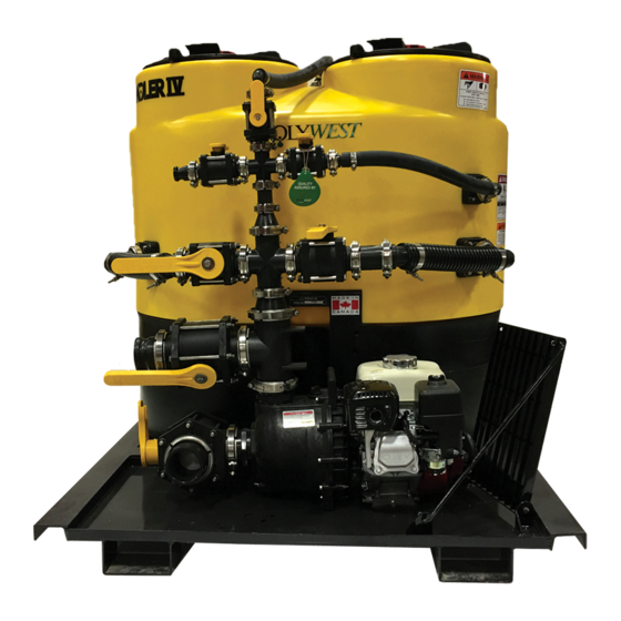
HOW THE SYSTEM WORKS TO THE NEW OPERATOR OR OWNER The handler consists of a plastic tank mounted near or on a sprayer or other water source unit, and a valve system plumbed for adding product to the machine. A patented... - Page 14 Handler IV (Customer Supplied Pump) Handler Tank Mounting Frame Handler Knife (Inside Tank - Not shown) Agitation Valves Jug Rinse Valve Tank Rinse Valve Suction Line (Under Tank) Suction Valve Discharge Port (To Sprayer) 10 Induction Port (From Pump) 11 Fresh Water Inlet...
- Page 15 The Handler IV can be adapted for use on any existing sprayer or water supply vehicle. It may be used for adding Check all fitting and connections for leaks.
-
Page 16: Plumbing Package System (3" Package)
Close all lids and open valve #5 (rotoflush valve) Place container into tank and puncture. Push the to rinse Handler tank (See Fig. 5.6). When rinsing is container down with consistent and even force to cut the complete, close valve #5 to stop water flow into Handler bottom of the container and to allow it to drain. - Page 17 Figure 5.3 Suction Valve - drawing from nurse tank position Figure 5.6 RotoFlush Valve Open valve #1 (suction valve) to allow mixture to be drawn from Handler tank. (See Fig. 5.7) Open Valve #3 (discharge valve) to allow mixture to be delivered to sprayer. (See Fig. 5.8) Repeat Steps #5 to #7 as necessary to rinse tank.
-
Page 18: Mixing Dry & Packaged Products
(Fig 5.3) gasoline engine driven (Fig. 5.9 & 5.10) Open one or both valves #4 & #6 (agitation valves) and fill Handler tank with appropriate amount of water to mix product. (Fig. 5.9 & 5.10) Slowly pour product into Handler tank. - Page 19 Once the desired mixture is achieved, close agitation valve(s) to prevent continued recirculation. Open valve #3 (discharge valve) to send Handler tank contents to sprayer tank. (See Fig 5.8) 10 Close valve #3 once tank is filled to desired level or all product has been delivered.
-
Page 20: Trouble Shooting
6. TROUBLE SHOOTING The Handler batch and induction tank is a simple causes and presents solutions to the problems. If you product adding system that employs either a suction or have a different problem, even after having read through plumbing system to place product into your sprayer tank. It... - Page 21 Suction line is drawing air. Incorrect valve setting. Reduce suction from sprayer tank by partially closing the valve. This will regulate the speed at which product mixture is drawn from the Handler. Dry Product Mixing Clogged suction lines. Granular product is insufficiently Force water back into the venturi by opening dissolved.
-
Page 22: Parts
Item Part Number Description Quantity Item Part Number Description Quantity 3” Plumbing Section 1 25-FC220 2” Worm Screw Clamp 54-79350 3” EPDM Hose 2.5FT 25-200G 2” EPDM Gasket 25-MV300BL 3” Manifold 3-Way Ball Valve 54-79250 2” EPDM Hose 2.5FT 25-V25153138BL 1 3/8”... -
Page 23: 3" Plumbing Package Breakdown W/ Pump
Item Part Number Description Quantity Item Part Number Description Quantity 3” Plumbing Section 1 25-FC220 2” Worm Screw Clamp 25-MV300BL 3” Manifold 3-Way Ball Valve 25-200G 2” EPDM Gasket 25-V25153138BL 1 3/8” 3 Way Handle Offset 54-79250 2” EPDM Hose 2.5FT 25-V25153SH Short Handle for Ball Valve... -
Page 24: Tank Parts Breakdown
Item Part Number Description Quantity 85-HKNIFE Handler Knife 86-H4T250 230 US Gallon Tank 86-H4T250STAND Handler 4 Stand 25-MBF220 2” FPTxFlange Bolted Bulkhead 2 25-SL200-54 2” MPTxFPT 45° Street Elbow 25-MBF100 1’ FPTxFlange Bolted Bulkhead 1 49-62532 15” Hinged Vented Lid... -
Page 25: Specifications
6. SPECIFICATIONS • Tank: Polyethylene, cone bottom. • Capacity: 230 US gallons or 870 liters. • Subframe: Steel • Fittings: fiberglass filled polypropylene • Hose: braided clear PVC (pressure side) or EPDM suction (suction side of system). • Clamps: all stainless steel. •...
Need help?
Do you have a question about the IV and is the answer not in the manual?
Questions and answers