
Related Manuals for Tuthill 4000 Series


Summary of Contents for Tuthill 4000 Series
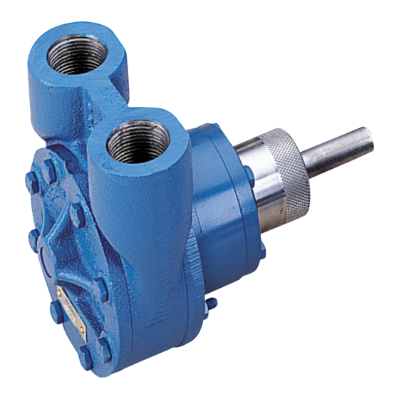
- Page 1 Installation and Service Instructions 4000 Series Pumps Excellence at work. Excellence in life.
-
Page 2: Table Of Contents
Table of Contents Introduction Warranty General Description Contact Information The Pumping Principle Proper Installation Method of Drive Relief Valve Protection 4100 Series 4300 Series Strainer Protection Startup 4101-4108 Parts List 4121-4128 Parts List Seal Replacement Pump Disassembly Inspection Pump Assembly Changing Rotation 4312-4316 Parts List Seal Replacement... - Page 3 Introduction The 4000 Series pumps have been certified to the requirements of the ATEX Directive 94/9/EC for use in Category II, Group 2 G applications. Read this manual before operating or working on the 4000 Series pumps. If additional information is required to facilitate operation or maintenance, contact the authorized Tuthill distributor shown at the back of this service manual.
-
Page 4: The Pumping Principle
Charge. Tuthill 4000 Series pumps are required to develop 25” mercury vacuum at 0 psi on factory test. While these pumps will develop as high as 27” of vacuum, it is a sound engineering practice to avoid extreme vacuum whenever possible. Select a pipe size to reduce line friction loss to a minimum. -
Page 5: Proper Installation
Tuthill 4000 Series pumps are supplied with both ports on the same plane. Pumps with this type of porting arrangement should always be installed with the ports facing upward to insure proper priming. If it is necessary to install the pump with the ports pointing to either side, it is recommended that the top port be the suction port. -
Page 6: Relief Valve Protection
Relief Valve Protection All 4000 Series models are positive displacement pumps. As the pump rotates, liquid is positively delivered to the discharge side of the pump. If the discharge line is closed off, pressure will increase until the drive stalls and/or fails, the pump breaks or ruptures, or the piping bursts. -
Page 7: Strainer Protection
WARNING All Tuthill pumps contain residual 200 SSU lube oil from the factory test. Determine if this is compatible with the fluid you are pumping. If the fluid is incompatible, consult the factory. If the pump is to operate at elevated temperatures, it should be brought up to operating temperature gradually. -
Page 8: 4101-4108 Parts List
4101-4108 Parts List 4121-4128 Parts List Item Description Item Description Housing Retaining Ring* Cover Assembly Mechanical Seal Idler Gear O’Ring Cover Screws Housing Plug Cover Gasket Rotor Housing Bushing * Models 4101/4121, 4102/4122, 4103/4123 & 4104/4124 only. Page 8 of 18... -
Page 9: Seal Replacement
• Inspect the shaft at the keyway, flat or tang. Any burrs will interfere with removal of the housing plug and bearing assembly. • Remove the housing plug with a face-type spanner wrench, available from Tuthill as part number 0L506. -
Page 10: Pump Disassembly
Pump Disassembly • Follow steps 1-5 from “Seal Replacement” above to remove the seal assembly • On models 4101/4121, 4102/4122, 4103/4123, and 4104/4145, remove the retaining ring from the shaft • Mark the cover and housing of the pump for proper re-assembly •... -
Page 11: 4312-4316 Parts List
4312-4316 Parts List 8 10 Item Description Item Description Cover Mechanical Seal Housing Retaining Ring Bracket Cover Screws Idler Gear Seal Gland Cover Screws Rotor Lockwasher O-Ring Gland Screws O-Ring Seal Replacement • Grip the pump firmly across the ports and secure the housing in a vise with the shaft end up •... -
Page 12: 4332-4336 Parts List
4332-4336 Parts List 15 6 12 13 14 Item Description Item Description Cover Retaining Ring Housing Thrust Washer Bracket Thrust Bearing Idler Gear Lip Seal Seal Gland Set Screw Adjusting Sleeve Cover Screws Rotor O-Ring Cover Screws O-Ring Lockwasher Mechanical Seal Gland Screws Page 12 of 18... -
Page 13: Seal Replacement And Resetting Of Clearances
Seal Replacement and Resetting of Clearances 1. Grip the pump firmly across the ports and opposite side of the housing in a vise with the shaft end up. 2. Remove any burrs or nicks on the shaft. Use a small, fine file if needed. 3. Remove the lip seal from the adjustment sleeve. -
Page 14: Pump Disassembly
Pump Disassembly The seal must be removed before the pump can be disassembled. Mark the cover, housing and bracket for proper re-assembly. Remove the cover screws, cover, housing, idler and rotor from the bracket Inspection Check the pump housing, rotor, idler gear, idler pin and cover for wear and chipped or broken teeth. There must not be any deep scratches or grooves on any of the following. -
Page 15: Changing Shaft Rotation While Maintaining Suction Ports
Changing Shaft Rotation While Maintaining Suction Ports Models 4312-4316 To maintain the same suction port and yet change shaft rotation from clockwise to counter-clockwise or vice versa please do the following. • Looking at the pump from the shaft end with the ports up, note the location of the V notch in the bracket •... -
Page 16: Changing Suction Ports While Changing Shaft Rotation
WARNING Failure to follow these instructions could result in serious bodily injury or death. Do not attempt to work on any Tuthill pump installation before completing the steps below. Disconnect the drive so that it cannot be started while work is being performed. Review the Material Safety Data Sheet (MSDS) applicable to the liquid being pumped to determine its characteristics and the precautions necessary to ensure safe handling. -
Page 17: Troubleshooting
Troubleshooting No fluid is delivered Pump works spasmodically • Power is not on • Leaky suction line • Net positive suction head available (NPSHA) is • Varying suction conditions lower than required for the inlet conditions and • Air or vapor in the fluid. the vapor pressure of the liquid pumped. -
Page 18: Introduction 3 Warranty
Warranty Tuthill Pump Group warrants its products against defective material and workmanship for 90 days from the date of startup or one year from date of shipment from Tuthill’s plant, whichever comes first. This warranty does not include products damaged by tampering, improper installation, abuse, or wear.
Need help?
Do you have a question about the 4000 Series and is the answer not in the manual?
Questions and answers