
Related Manuals for IDS 805


Summary of Contents for IDS 805
- Page 1 Training Manual Installer Training 805 Stock Code: 860-1-B08-MN 805S Stock Code: 860-1-0808M...
-
Page 2: Table Of Contents
Contents Features ________________________________________________________________________________________________3 Hardware _______________________________________________________________________________________________4 Serial Output (805S Only) ____________________________________________________________________________ 8 Dialler Progress Mode (805 Only) ______________________________________________________________________ 9 Programming __________________________________________________________________________________________ 10 Programming and locations _________________________________________________________________________ 10 Installer Mode _____________________________________________________________________________________ 10 Location 11 Trouble Conditions. ________________________________________________________________________________ 25 User Operation ________________________________________________________________________________________ 26... -
Page 3: Features
Fax defeat allows download access to the panel with other devices connected to the phone line. (805 ONLY) Dual reporting provides for duplicated reporting to two independent central base stations. (805 ONLY) Programmable silent or audible panic. -
Page 4: Hardware
Hardware Default Button IDS 805 Dialler Board Connectors IDS 805s Serial Connector Connectors Keypad Siren 16V AC Zones Programmable +12V Output Radio Tx ... - Page 5 Dialler A transformer of no less than 30VA should be used to supply 16V AC to the IDS805 alarm panel. Radio Tx Power supply to any radio transmitter While it may seem unnecessary to some, in order to carry the full transmit current without any significant volt drop in the cable length between the battery and the radio, it is necessary to use mains cable that is rated no less than 5 amps.
- Page 6 Make sure that when connecting the keypad bus that Data on the keypad is connected to D on the 805 and the same with CK, that it is connected to C. Keypad Connector The keypad has a 3V LED output which mimics the armed LED. I.e. when the system is armed the LED will come on.
- Page 7 Depending if the device is normally open or normally closed, will depend on how the end-of-line resistor is connected. The end-of-line resistor is what the Alarm Panel looks for to determine if there has been a violation or not. Therefore, it is very important to connect it correctly! The end of line resistor must be 3K3...
-
Page 8: Serial Output (805S Only)
LED connected to output Serial Output (805S Only) The serial connection outputs an IDS serial protocol that can communicate to any device which has the protocol implemented. The serial connector can also be used to upload and download settings via IDSwift2 and the IDS USB to Serial convertor. -
Page 9: Dialler Progress Mode (805 Only)
Standby Standby Dialling Kiss-off Seizing Kiss-on Data Exercise: Remove power from the 805 alarm, press and hold the default button. While holding the button put connect the battery leads to the battery. Keep holding for 3 seconds and then release. -
Page 10: Programming
Programming Programming and locations Programming the IDS805 is putting values into a location. A location is an area of memory that stores a value to control the system when a task needs to be performed. Each location controls different tasks or a different aspect of a task. -
Page 11: Location
Location A location is a single tiered location holding a single value. The location is entered and the value is inserted confirmed by the star key. Once confirmed the location is exited automatically. The following steps show how to program standard locations. Keypress Explaination Visual Indicator... - Page 12 Examples: on how to read the data in a location. Value 3 Value 10 Exercise: 1. Enter programming. 2. Enter Location 8. What is the value in this location? _______________ Location 0: Defaulting There are two ways of resetting the system back to factory default, hardware button, described on page 8 or via programming.
- Page 13 Location 1 to 8: Zone Types A zone type is how a zone acts when the alarm is armed or disarmed. A value is associated with each zone type and when entered into the zones location it changes that zone to the type it represents. Value Type Explanation Disable...
- Page 14 Location 9: Entry / Exit Options This location changes the way the alarm reacts when the alarm needs to be armed. If any of the options below are chosen and are not met, the alarm will not be ready to arm. Value Entry / Exit Follower Entry / Exit...
- Page 15 Location 11: Tamper per Zone Tamper is a way of monitoring a device for any type of interference, without having to use extra cable. Tamper is always active even when the alarm is disarmed. Value Description Disable Enable When enabling tamper per zone the 3k3 end of line resistor is replaced by 12K and 4K7 ohm resistors, which are placed in parallel, as can be seen in the diagram below.
- Page 16 Location 13: Stay Arming Options Stay arming is the ability to arm the system and at the same time have selected zones bypassed automatically. All active zones will be instant zones, including entry/exit zones. To stay arm, press and hold [5] until armed light comes on. Value Action The alarm will automatically arm in the stay mode if a user code is entered but no entry exit zone is triggered...
- Page 17 Location 18: Exit Delay Period This is the time a person has from entering their code or using the quick arm key, [1], to exiting the building through the entry exit zones, without setting the alarm off. Value Time-out Value Time-out Value Time- 0.25 sec...
- Page 18 The IDS 805 has 5 positively triggered outputs. Each output triggers with, direct current (DC) 12V and can supply approximately 100mA of current. If more current is required please use a 12V positively triggered relay to supply current from a different power source.
- Page 19 Download via software is complete. Complete Location 42: Phone Number Options and Dialling Options (805 Only) These options guide the alarm when it is required to communicate using the telephone line. Each telephone number has 16 locations, for 16 digits per number. If this is not enough digits the the two numbers can be joined together to create a 32 digit number if required.
- Page 20 Location 64 to 79: Secondary Telephone Number/Serial Telephone Number 805: This is the second number that can be dialled as a backup for the primary number should there be a failure to communicate on that number. The same rules apply as the primary telephone number.
- Page 21 Location 80 to 133: Reporting Codes These are the codes that the device at the monitoring company will turn into the corresponding action for the operator to read and know what the incident is and react accordingly. Note: Not required for Contact-ID. To disable a Contact-ID reporting code, enter 00 into the location Location Description Location...
- Page 22 Location 142: Zone Trip Count This and location 143 are also known as “double knock” by some. What this means is that, if a follower zone trips this many times, while the system is armed, in the time entered into location 143. Location 143: Zone Trip Count Time Delay The zone must trigger the number of times set in location 142, within the time period set in this location.
- Page 23 The number of times the system will try and dial if communication fails. By default this is set to 4. Location 152 to 155: Secondary Communicator Account Code (805 Only) For dual reporting discussed earlier this is the second account code if needed.
- Page 24 Location 158 to 165: Zone Programmable Outputs If a zone is violated and an output has been associated with it, that output will trigger. Note: If the zone is only active when the alarm is armed, i.e. an instant zone, then the output will only activate when the system is armed.
-
Page 25: Trouble Conditions
Trouble Conditions. Hold down the [7] until the beep If the POWER LED is flashing (or if so programmed, the keypad is beeping) hold down the [7] key for one second. The ARMED, AWAY, and READY indicators will start flashing to show that the keypad is in the TROUBLE viewing mode. -
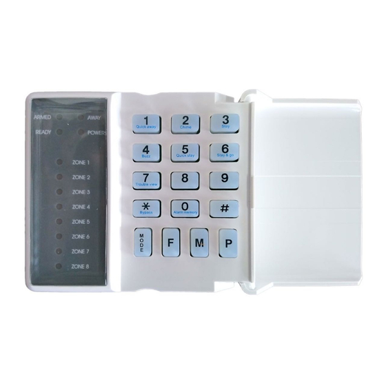
Page 26: User Operation
User Operation Understanding the Keypad Indicators Feedback Indicators Keys Feedback Indicators Feedback Indicators Armed Indicator (Red) Away Indicator (Red) This will be on when the system is This will be on when armed armed in away and stay modes in the away mode Ready Indicator (Green) Power Indicator (Red) The ready indicator comes... -
Page 27: Keys
Keys By pressing this key until the exit beeps begin will away arm the system, without having to enter a user code This is to enter which zones are to beep the keypad if they are violated will the system is disarmed To enable the zones which are to be automatically bypassed when armed in the stay mode To enter the zones which are to buzz the keypad if violated, when the... -
Page 28: Away Arming
Away Arming Away arming is when the system arms with all entry / exit zones actively monitoring any violations, to trigger the entry / exit cycle. The entry / exit cycle is the time programmed to allow the person to either exit or enter and insert a user code, without the system going into an alarm state. -
Page 29: Stay Zones
Stay Zones These are the zones that will be automatically disabled when the system arms in the stay mode. To create stay zones: 1. Press and hold the [3] key for 3 seconds 2. Press the [zone number] keep selecting all required zones 3. -
Page 30: Adding A Maid's Code
Adding a Maid’s Code A maid’s code is a code that can only disarm the alarm if it has been used to arm the alarm. If a general user code has been used to arm, the maids code will not be able to disarm. [*] [master code] [*] [1] [4] [*] [code] [*] 1. -
Page 31: Glossary Of Terms
Glossary of terms Alarm Memory This is the history of the most recent violations that occurred the last time the system was armed. Alarm memory is always cleared when the system is armed. In this mode, violating a zone will activate an alarm condition. If the system is programmed accordingly, it will cause a reporting code to be sent to the monitoring company. -
Page 32: Ids Analogue Receiver Training
IDS Analogue Receiver Training Features Can operate in stand-alone mode or connected to an IDS805 200 users in stand-alone mode 16 users when connected to the IDS805 3 LEDs for status information Programmed via an 8 way dip switch All arm or disarm actions logged by user... -
Page 33: Connections
Connections IDS 805 IDS Analogue Rx Mk ll Antenna Power LED Bus Status LED Dip Switch Function LED Tamper Switch Bus Status LED: On - Indicates if the receiver is connected to the keypad bus Flashing – Not connected to the bus... -
Page 34: To Default Receiver
5. Hold a button on the remote transmitter down until the keypad gives the confirmation beep [*] [1][2][3][4] [2][*] [4][4][3][2][*] Press the button on the remote transmitter until the keypad gives a Master User User confirmation beep Code Number Code Default button assignment for the remote transmitter Disarm IDS Remote Transmitter... -
Page 35: Delete A Remote Transmitter
Delete a Remote Transmitter To delete a remote transmitter: 1. Press and hold the [*] key for 3 seconds 2. Enter the master code 3. Enter the user number followed by [*][*] [*] [1][2][3][4] [2][*][*] Master User Code Number Button Properties Changing button properties for a remote transmitter will change the properties for all remote transmitters. -
Page 36: Relay Pulse Or Toggle
Assign a Relay to a Button To assign a button to trigger a relay: 1. Switch dip switch 5 on 2. Switch dip switch 8 on 3. Switch dip switch 1 on for relay 1 or dip switch 2 on for relay 2 1 for relay 1 4. -
Page 37: Relay Retrigger Protection
Relay Retrigger Protection Retrigger protection will not allow the relay to trigger again for 20 seconds To setup retrigger protection: 1. Switch dip switches 5 and 7 on 2. Switch dip switch 8 on 3. Select which relay by switching either dip switch 1 or 2 or both on 4. -
Page 38: Learning A Panic Remote
Learning a Panic Remote To teach a remote as a panic remote: 1. Switch dip switch 6 on 2. Press a button on the remote transmitter 3. Switch dip switch 6 off...
Need help?
Do you have a question about the 805 and is the answer not in the manual?
Questions and answers
How to bypass some zones when you are home