
Summary of Contents for 123electric Smart BMS gen 3
- Page 1 Manual Rev 1 123electric The Netherlands E-mail: info@123electric.eu www.123electric.eu...
-
Page 2: Table Of Contents
Multiple battery cells or packs different cell chemistries ......14 parallel ..........24 The App ............15 Switching combined charger/inverter ........24 First connection ......... 15 Separate battery sections ..... 25 App Settings ..........15 Dashboard ..........17 123electric The Netherlands E-mail: info@123electric.eu www.123electric.eu... -
Page 3: Introduction
Cell temperature and current are 1.5 – 5 volt. also very important, in order to guarantee a 123electric The Netherlands E-mail: info@123electric.eu www.123electric.eu... -
Page 4: Package Contents
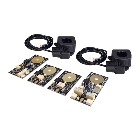
The standard 4 cells/12V package contains: 1x Begin Cell Board 1x End Cell Board 2x Between Cell Boards 2x Dual range current sensors 20A/500A Piece of 0.75 mm² wire for the interconnections Connector unlock tool 123electric The Netherlands E-mail: info@123electric.eu www.123electric.eu... -
Page 5: Specifications
Dual range current sensor measurement specifications (4x loop, see hardware installation step 6) <5A >5A measurement Blind spot around Max measured measurement resolution zero current resolution 12.5 mA 313 mA ± 75 mA 125 A 123electric The Netherlands E-mail: info@123electric.eu www.123electric.eu... -
Page 6: Schematic Overview
Schematic overview 123electric The Netherlands E-mail: info@123electric.eu www.123electric.eu... -
Page 7: Hardware Installation
When the flashing LEDs stop panels, MPPT, charger and the load. somewhere in the middle of the cell chain, there is an error, in this case check the wiring. 123electric The Netherlands E-mail: info@123electric.eu www.123electric.eu... - Page 8 Step 1. Step 2. Step 4. Step 3. 123electric The Netherlands E-mail: info@123electric.eu www.123electric.eu...
- Page 9 For example when charging, you should see a positive current number next to the solar panel image. 123electric The Netherlands E-mail: info@123electric.eu www.123electric.eu...
- Page 10 Step 6. 123electric The Netherlands E-mail: info@123electric.eu www.123electric.eu...
- Page 11 If not, connect an energy efficient power relay to the potential free contacts so the BMS is able to switch the power to these devices. See the next chapter for more information. 123electric The Netherlands E-mail: info@123electric.eu www.123electric.eu...
-
Page 12: Controlling External Components
CHARGE relay contacts are closed (pin 1 & 2 are open). Note: when switching inductive loads like a relay/contactor, make sure there is a protection against flyback of the coil. A simple example is the flyback diode parallel to the coil. 123electric The Netherlands E-mail: info@123electric.eu www.123electric.eu... -
Page 13: Hardware Setting
2.2V 2.3V 2.4V 2.5V 2.6V (for LTO) 2.7V 2.8V 2.9V 3.0V 3.1V 3.2V 3.3V 3.4V (for LiFe4PO) 3.5V 3.6V 3.7V 3.8V 3.9V 4.0V (for NMC) 4.1V 4.2V 4.3V 4.4V 4.5V 4.6V 4.7V 4.8V 4.9V 123electric The Netherlands E-mail: info@123electric.eu www.123electric.eu... -
Page 14: Keep The Batteries In Perfect Condition
A LiFePO4 cell voltage vs. SOC curve. The voltage is dependent on the percentage energy left in the cell (SOC). Recommended threshold values for different cell chemistries Cell chemistry Minimum voltage Balance voltage Maximum voltage (Vmin) (Vbalance) (Vmax) LiFePO4 2.9V 3.4V 3.7V 2.15V 2.6V 2.7V 3.43V 4.0V 4.1V Li-ion 3.43V 4.1V 4.15V 123electric The Netherlands E-mail: info@123electric.eu www.123electric.eu... -
Page 15: The App
The standard current relay to control external devices will be sensors supplied in the set are dual range switched off. 500A – 20A. Critical mode: Read extra info section B. 123electric The Netherlands E-mail: info@123electric.eu www.123electric.eu... - Page 16 App, you can run a simulator. screen is switched on. Both relays to control Support: You can contact the app developer external devices be switched off. and give your feedback. The App version will be showed here. 123electric The Netherlands E-mail: info@123electric.eu www.123electric.eu...
-
Page 17: Dashboard
Stored power in kWh, presentation you will find details like: Incoming / outgoing power, Total battery pack consumed current, consumed power, voltage. consumed energy today, total of consumed energy. 123electric The Netherlands E-mail: info@123electric.eu www.123electric.eu... -
Page 18: Battery Details
Green values are in the safe range, yellow maximum cell temperature, “Tl” exceeding values shows balancing cells and red values minimum cell temperature. are out of the safe range cells (above V max or below V min for example) 123electric The Netherlands E-mail: info@123electric.eu www.123electric.eu... -
Page 19: Algorithm
> T-min > T-min AND cell temperature Cell temperature > T- AND cell temperature Cell temperature > T- < T-max < T-max AND cell No cell AND cell No cell communication communication communication communication 123electric The Netherlands E-mail: info@123electric.eu www.123electric.eu... -
Page 20: Module Details
Connector for the current sensor of the incoming current (solar). Current sensor consumers Connector for the current sensor of the outgoing current (consumers). Extended data output Data output for external modules to receive information about the battery pack. 123electric The Netherlands E-mail: info@123electric.eu www.123electric.eu... -
Page 21: Between Boards
ON when the board is balancing. BMS IN Data input from the previous cell board. Use one of the two holes. BMS OUT Data output to the next cell board. Use one of the two holes. 123electric The Netherlands E-mail: info@123electric.eu www.123electric.eu... -
Page 22: End Board
Relay for cutting off chargers, MPPT, solar chargers etc. In case of full batteries. Load relay contacts Relay for cutting off consumers like inverters, etc. In case of empty batteries. Extended data output Data output for external modules. 123electric The Netherlands E-mail: info@123electric.eu www.123electric.eu... -
Page 23: Troubleshooting
Press and hold the blue button until the BMS. the LED flashes fast several times. Now 1. Restart the App and check in de Settings release the button. The calibration is done. screen if the BMS appears. 123electric The Netherlands E-mail: info@123electric.eu www.123electric.eu... -
Page 24: Appendix
In this case you only need 1 and use the charge relay for the BMS for 4S (4 cell groups). enable/disable signal of the charger and the load relay for the enable/disable signal of the inverter. 123electric The Netherlands E-mail: info@123electric.eu www.123electric.eu... -
Page 25: Separate Battery Sections
In this case twisted pair wire will be used. The data connection has to be galvanic isolated. The last Cell Board of the first battery bank in the cell chain doesn’t have to be modified. 123electric The Netherlands E-mail: info@123electric.eu www.123electric.eu... - Page 26 The picture below shows a setup with separated battery banks. 123electric The Netherlands E-mail: info@123electric.eu www.123electric.eu...