Advertisement
Available languages
Available languages
MANUALE DI USO E
INSTALLAZIONE
USE AND INSTALLATION
MANUAL
BETRIEB UND
INSTALLATIONSANLEITUNGEN
Climatizzatore con motocondensante a scomparsa
Air Conditioner with recessed condensing unit
Klima-Anlage mit verdeckt eingebauter
Kondensatoreinheit
MONO
ELSKOV - 12 H9
ELSKOV - 18 H9
DUAL
ELSKOV2 - 14 H9
ELSKOV2 - 18 H9
Versione 1.0
TRIAL
ELSKOV3 - 24 H9
Advertisement

Related Manuals for Tekno Point ELSKOV-12


Summary of Contents for Tekno Point ELSKOV-12
- Page 1 MANUALE DI USO E INSTALLAZIONE USE AND INSTALLATION MANUAL BETRIEB UND INSTALLATIONSANLEITUNGEN Climatizzatore con motocondensante a scomparsa Air Conditioner with recessed condensing unit Klima-Anlage mit verdeckt eingebauter Kondensatoreinheit TRIAL MONO ELSKOV3 - 24 H9 ELSKOV - 12 H9 ELSKOV - 18 H9 DUAL ELSKOV2 - 14 H9 ELSKOV2 - 18 H9...
- Page 2 DÉCLARATION DE CONFORMITÉ KONFORMITÄTSERKLÄRUNG Descrizione - Description - Beschreibung Modello - Model MONO/MULTISPLIT DC INVERTER ARIA-ARIA ELSKOV-12 | H9 ELSKOV-18 H9 MONO/MULTISPLIT DC INVERTER AIR TO AIR ELSKOV2-14 | ELSKOV2-18 H9 MONO/MULTISPLIT DC ONDULEUR AIR-AIR ELSKOV3-24 H9 MONO/MULTISPLIT DC INVERTER LUFT-LUFT Io fi...
- Page 3 ITALIANO INDICE capitolo pagina 1. INFORMAZIONI GENERALI 2. DESCRIZIONE 3. VERIFICHE PRELIMINARI 4. INSTALLAZIONE 5. MANUTENZIONE DELL’ UNITÀ 6. AUTODIAGNOSI...
- Page 4 La validità della garanzia decade nel caso non siano e/o raffreddamento dell’aria. Una diversa applicazione, non rispettate le indicazioni sopra menzionate. espressamente autorizzata da Tekno Point, è da ritenersi La documentazione fornita con l’unità deve essere impropria e quindi non consentita.
- Page 5 Per anomalie non contemplate da questo manuale, Tekno Point non emette disegni o specifiche di impianti di interpellare tempestivamente il Servizio Assistenza. Tekno allacciamento. Qualsiasi deroga alle prescrizioni contenute Point declina ogni responsabilità per qualsiasi danno dovuto...
- Page 6 INFORMAZIONI GENERALI Il libretto Uso e manutenzione è parte integrante Non disperdere nell’ambiente le parti degli imballaggi, dell’apparecchiatura; si raccomanda di leggerlo e di o lasciarli alla portata di bambini in quanto potenziali conservarlo con cura. fonti di pericolo. Smaltire gli imballi secondo le Togliere l’imballo solo con apparecchiatura posta normative vigenti nel paese.
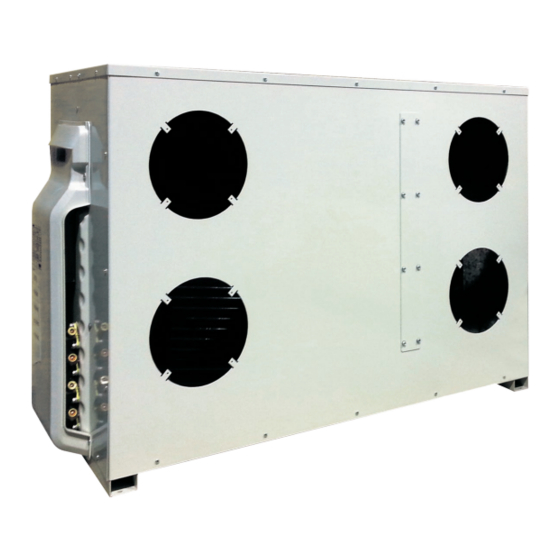
- Page 7 DESCRIZIONE 2. DESCRIZIONE Il prodotto reale può essere diverso, si prega di fare riferimental prodotto reale mension of the unit 2.1 COMPONENTS AND MEASURES 2.2 COMPONENTS AND MEASURES Outline dimension of th Outline dimension of the unit Outline dimension of th ELSKO ELSKO 2 4 H9 SAVH12A-A1NB(O)
- Page 8 VERIFICHE PRELIMINARI 3. VERIFICHE PRELIMINARI 3.1 ATTREZZATURA 1. Livella 8. Tagliatubi 9. Nastro di misurazione 2. Trapano 3. Chiave esagonale 10. Manometri 4. Chiave inglese 11. Carotatrice 5. Pompa per il vuoto 12. Aspirapolvere 6. Giravite 13. Cerca Fughe 7. Cartellatrice 14.
- Page 9 30 cm 50 cm 30 cm 50 cm 50 cm 10 cm 4.2 MODALITÀ DI INSTALLAZIONE ELSKOV-12 H9 Aria in uscita Aria in uscita Aria in entrata unità invisibile parete perimetrale unità invisibile parete perimetrale Distanza max dal muro: 4 m lineari, 8 m in versione prolungata.
- Page 10 Ø 200 si possono raccordare tramite un “Y” in usufruire di una presa AUX . Contattare il servizio tecnico un unico condotto da Ø 300 o area equivalente di Ø 628 cm Tekno Point per maggiori informazioni. Distanza max 1 m. MANUALE INSTALLAZIONE ELFO...
- Page 11 outdoor unit. ● Make sure the support can withstand at least four times INSTALLAZIONE of the unit weight. ● The outdoor unit should be installed at least 3cm above the the floor in order to install drainjoint. ● For the unit with cooling capacity of 2300W~5000W, 6 4.7 TUBO DI DRENAGGIO expansion screws are needed;...
- Page 12 INSTALLAZIONE 4.13 PROCEDURA DI MONTAGGIO La motocondensante ELFO DEVE ESSERE INSTALLATA - Collegare i tubi di collegamento all’unità motocondensante e all’unità Interna. IN POSIZIONE ACCESSIBILE per eventuali interventi tecnici in sicurezza, in caso contrario i CAT (centri - Collegare la pompa per vuoto al raccordo (aspirazione), assistenza tecnica) potranno...
- Page 13 INSTALLAZIONE La presenza di aria e umidità all’interno del sistema • Per ciascuno dei circuiti frigoriferi, pressurizzare i tubi refrigerante può avere i seguenti effetti indesiderati: agendo dalla valvola di scarico del gas: PROVA DI TENUTA TUBAZIONI E VUOTO • Aumento della pressione del sistema 1.
- Page 14 Installation of outdoor unit INSTALLAZIONE 3. Pretightening the union nut with hand. 4. Tighten the union nut with torque wrench by referring to the sheet below. Hex nut diameter Tightening torque (N . m) pipe joint diametro tubazione [mm] coppia di serraggio [Nm] Φ...
- Page 15 INSTALLAZIONE 4.20 ESECUZIONE DEL VUOTO • Usare una pompa per eseguire il vuoto, è severamente Se dopo 3 ore totali la pressione non è ancora scesa sotto i vietato spurgare il refrigerante. -755 mmHg, bisogna individuare la perdita e ripararla. •...
- Page 16 INSTALLAZIONE 4.22 RILEVAMENTO PERDITE 1. Verificare se ci sono perdite con rilevatore di perdite. Applicare acqua e sapone in posizione sospetta e mantenere l’acqua e sapone per più di 3 minuti. Se ci sono bolle 2. Se la sonda di perdita non è disponibile, si prega di che escono da questa posizione, identificare la perdita e utilizzare acqua e sapone per il rilevamento delle perdite.
- Page 17 MANUTENZIONE 5. MANUTENZIONE UNITÀ 5.1 MANUTENZIONE ORDINARIA - Efficienza sicurezze. La manutenzione periodica è fondamentale per mantenere in perfetta efficienza l’unità sia sotto l’aspetto funzionale che - Tensione elettrica di alimentazione. energetico. - Assorbimento elettrico. Il piano di manutenzione che il Centro Assistenza Tecnica - Serraggio connessioni elettriche.
- Page 18 MANUTENZIONE 5.4 EVENTUALI ANOMALIE E POSSIBILI RIMEDI Anomalia Causa Rimedio U/INS/CAT Mancanza di tensione Verificare la presenza di tensione Interruttore generale in pos. OFF Verificare sistemi di sicurezza a monte Tensione di alimentazione bassa Verificare linea di alimentazione Il compressore non si avvia Condensatore del compressore guasto Sostituire il componente...
- Page 19 6. AUTODIAGNOSI 6.1 CODICI DI ERRORE Codice errore Problema Modalità recupero gas refrigerante Pulizia filtri Trial run Sbrinamento o ritorno olio al compressore in pompa di calore Protezione surriscaldamento temperatura di scarico Protezione sovraccarico del sistema Protezine sovraccarico del compressore Protezione anti gelo Protezione alta pressione / Errore flussostato Protezione bassa pressione del sistema...
- Page 20 Protezione da malfunzionamento del circuito di rilevamento della corrente del compressore Protezione perdita di fase del compressore Protezione antigelo Protezione da malfunzionamento del circuito di rilevamento della corrente del ventilatore dell'unità esterna Errore configurazione jumper unità interna Errore del circuito "zero crossing detection" Errore motore ventola unità...
- Page 21 Errore sensore temperatura ambiente unità interna Errore sensore temperatura tubo unità interna Errore sensore temperatura ingresso aria Errore sensore temperatura uscita aria Errore sensore temperatura scarico compressore Errore sensore temperatura IPM Errore sensore temperatura tubo liquido Errore sensore temperatura tubo gas Errore sensore temperatura scarico MANUALE INSTALLAZIONE ELFO...
-
Page 23: Table Of Contents
ENGLISH INDEX chapter page 1. GENERAL INFORMATION 2. DESCRIPRION 3. PRELIMINARY CHECKS 4. INSTALLATION 5. MAINTENANCE OF UNITY 6. SELF-DIAGNOSIS... -
Page 24: General Information
The guarantee is invalidated if they do not meet the cooling of the air. A different application, unless expressly above mentioned directions. authorized by Tekno Point, is to be considered improper and The documentation supplied with the unit must be delivered therefore not permitted. - Page 25 For anomalies do not by this manual, contact the Customer Tekno Point does not emit drawings or specifications of the Service. Tekno Point accepts no responsibility for any connection systems. Any departure from the requirements...
- Page 26 Before installing the equipment read carefully and keep the 7. The connections to the machine must be performed by user manual and general conditions tekno point here below. trained and competent personnel and must meet all safety standards and protection of health at the time and in force in 1.
-
Page 27: Descriprion
DESCRIPTION 2. DESCRIPTION Actual product may be different, please refer to the actual product. mension of the unit 2.1 COMPONENTS AND MEASURES 2.2 COMPONENTS AND MEASURES Outline dimension of th Outline dimension of the unit Outline dimension of th ELSKO ELSKO 2 4 H9 SAVH12A-A1NB(O) SAVH12A-A1NB(O) -
Page 28: Preliminary Checks
PRELIMINARY CHECKS 3. PRELIMINARY CHECKS 3.1 EQUIPMENT 1. Level 8. Cutter 9. Measuring tape 2. Drill 3. Hexagonal wrench 10. Pressure gauges 4. Wrench 11. Core drill 5. Vacuum pump 12. Vacuum cleaner 6. Screwdriver 13. Search Getaway 7. Flaring 14. -
Page 29: Installation
MINIMUM DISTANCES TO BE RESPECTED FRONT 30 cm 30 cm 50 cm 50 cm 10 cm 4.2 INSTALLATION MODE ELSKOV-12 H9 Air output Air output Inlet air invisible unit perimeter wall invisible unit perimeter wall... - Page 30 In particular conditions, you may need to make use of from Ø 200 can connect via a “Y” in a single conduit from Ø Ø an AUX jack. Contact technical service Tekno Point for more 300 or equivalent area of 628 cm2. Max distance of 1 m.
- Page 31 outdoor unit. ● Make sure the support can withstand at least four times INSTALLATION of the unit weight. ● The outdoor unit should be installed at least 3cm above the the floor in order to install drainjoint. ● For the unit with cooling capacity of 2300W~5000W, 6 4.7 DRAINAGE PIPE expansion screws are needed;...
- Page 32 INSTALLATION 4.13 ASSEMBLY PROCEDURE The condensing ELFO SHALL BE INSTALLED IN - Connect the unit and connecting pipes condensing unit Inner. POSITION ACCESSIBLE technician in safely, otherwise the CAT (service centers) may refuse the intervention. - Connect the vacuum pump to the fitting (suction), set in THE CONDENSING MUST NOT BE INSTALLED AS motion and make sure that the needle drops to - 0.1 MPa OUTSIDE IN WINTER MAY CAUSE DAMAGE.
- Page 33 INSTALLATION The presence of air and moisture in the refrigerant system • For each of the refrigerant circuits, acting pressurize the may have the following side effects: tubes from the gas exhaust valve: PROVA DI TENUTA TUBAZIONI E VUOTO • Increased pressure in the system 1.
- Page 34 ● Never cut the power connection wire to prolong or shorten the distance. 3. Fix the power connection wire and signal control wire with wire clip (only for cooling and heating unit). 4. Reinstall the handle. ELSKOV-12 H9 ELSKOV 2-14 H9 ELSKOV-18 H9 handle...
- Page 35 INSTALLATION 4.20 PERFORMANCE OF EMPTY • Use a pump to run the vacuum, it is strictly forbidden to hour. If after 3 total hours the pressure is not yet dropped drain the coolant. below -755 mmHg, you have to find the leak and repair it. •...
- Page 36 INSTALLATION 4.22 LEAK DETECTION 1. Check for leaks with leak detector. Apply soap and water in the suspected position and maintain the soap and water for more than 3 minutes. If there are 2. If the leakage probe is not available, please use soap and bubbles coming out from this position, identify and restore water for leak detection.
-
Page 37: Maintenance Of Unity
MAINTENANCE UNIT 5. MAINTENANCE UNIT 5.1 ORDINARY MAINTENANCE - Efficiency safeties. Regular maintenance is essential to maintain the efficiency of the unit both in terms of operation and energy. - Power supply voltage. The maintenance plan that the Technical Assistance - Power consumption. - Page 38 MAINTENANCE UNIT 5.4 FAULTS AND POSSIBLE REMEDIES Anomalia Causa Rimedio U/INS/CAT Power failure Verify the presence of voltage main switch in pos. OFF Check the upstream safety systems low supply voltage Check power line The compressor does not start Fault compressor condenser Replace the part compressor failure Replace the part...
-
Page 39: Self-Diagnosis
6. SELF-DIAGNOSIS 6.1 ERROR CODES Codice errore Problema Refrigerant gas recovery mode Filter cleaning Trial run Defrost or oil return to the compressor in heat pump Exhaust temperature overheat protection System overload protection Compressor overload protection Frost protection High pressure protection / Flow switch error Low system pressure protection Refrigerant leakage protection / Valve block protection 4-way malfunction protection... - Page 40 Protection against malfunction of the compressor current detection circuit Compressor phase loss protection Air frost protection Protection against malfunction of the fan current detection circuit of the outdoor unit Indoor unit jumper configuration error Zero crossing detection circuit error Indoor unit fan motor error Communication error between UI and EU reported in UI Communication error between IU and EU reported in the EU Communication error between UI and wired command...
- Page 41 Indoor unit room temperature sensor error Indoor unit tube temperature sensor error Air inlet temperature sensor error Air outlet temperature sensor error Compressor discharge temperature sensor error IPM temperature sensor error Liquid tube temperature sensor error Gas pipe temperature sensor error Drain temperature sensor error USE AND INSTALLATION MANUAL ELFO...
- Page 43 DEUTSCH INDEX Kapitel Seite 1. ALLGEMEINE INFORMATIONEN 2. BESCHREIBUNG 3. EIGENDIAGNOSE 4. INSTALLATION 5. WARTUNG 6. ANHÄNGE...
- Page 44 1. ALLGEMEINE INFORMATIONEN 1.0 SYMBOLEN Folgenden Symbole werden in dieser Anleitung und/oder in dem Gerät verwendet: GEFAHR: Bitte beachten unbedingt diese END-USER: Informationen, Paragraph, Anweisungen. Wenn die hier notierten Aktionen Kapitel Anleitungen, welche nicht korrekt durchgefuehrt werden, Es koennte Benutzer intessieren. zur schweren Verletzungen führen.
- Page 45 1.3 ZUGELASSENE VERWENDUNG UND VORSCHRIFTEN Diese Geräte wurden zum Heizen und / oder Kühlen der Luft feststellen sollten, vermerken Sie dies nach Erhalt des Gerätes in Wohngebieten oder im Tertiärbereich entwickelt. Eine andere auf dem Lieferschein: Bitte überprüfen Sie alle Teile, um vom Hersteller nicht ausdrücklich genehmigte Anwendung gilt sicherzustellen, dass der Transport keine Schäden verursacht als nicht bestimmungsgemäß...
- Page 46 1.6 GRUNDLEGENDE SICHERHEITSBESTIMMUNGEN Wir erinnern Sie daran, dass die Verwendung Es ist verboten, die aus dem Gerät kommenden elektrischen Produkten, Strom verbrauchen, Kabel zu ziehen, abzuziehen oder zu verdrehen, auch wenn Einhaltung einiger grundlegender Sicherheitsregeln das Gerät vom Stromnetz getrennt ist. voraussetzt, wie zum Beispiel: Das Öffnen der Zugangstüren zu den Innenteilen des Geräts ist verboten, wenn das System nicht mit dem Hauptschalter...
- Page 47 Entsorgen Sie Verpackungsteile nicht in der Umwelt Vergewissern Sie sich nach Erhalt, dass keine Transport- und lassen Sie sie nicht in Reichweite von Kindern, da und / oder Handhabungsschäden vorliegen und das sie potenzielle Gefahrenquellen darstellen. Entsorgen erforderliche Zubehör in der Verpackung vorhanden ist. Sie die Verpackung gemäß...
- Page 48 2. ELFO EINHEIT BESCHREIBUNG 2.1 TECHNISCHE DATEN 2.1.1 ELFO monosplit ELFO Monosplit DC inverter ELFO monosplit Codice ELFO-12 ELFO-18 Alimentazione - Power Supply - Alimentation éléctrique V - Hz- F 230 - 50 - 1 Nominale W/BTU 3500/12000 5200/17742 Potenza - Puissance Capacity Min/Max 1400/4200...
- Page 49 2.1.2 ELFO Multisplit ELFO Multisplit DC inverter ELFO multisplit Codice ELFO2-14 ELFO2-18 ELFO3-24 Tipo -Type - Typologie R410a Refrigerante Refrigerant Carica refrig. standard - Gaz - Refrigerant 1,10 1,00 1,30 Réfrigérant Carica aggiuntiva oltre la precarica gr/m Alimentazione - Power Supply - Alimentation éléctrique V - Hz- F 230 - 50 - 1 Nominale...
- Page 50 2. BESCHREIBUNG Das tatsächliche Produkt kann abweichen, beziehen Sie sich bitte auf das tatsächliche Produkt mension of the unit Outline dimension of th Outline dimension of the unit Outline dimension of th PRODUKT ABMESSUNGEN 2.2 PRODUKT ABMESSUNGEN ELSKO ELSKO 2 4 H9 SAVH12A-A1NB(O) SAVH12A-A1NB(O) SAVH12A-A1NB(O)
- Page 51 EINZUHALTENDE MINDESTABSTÄNDE 30 cm linke/rechte Seite Oberseite 50 cm 30 cm 50 cm 50 cm 10 cm 3.2 INSTALLATIONMOEGLICHKEIT ELSKOV-12 H9 ABLUFT ABLUFT LUFTEINLASS ELFO AUSSENWAND ELFO AUSSENWAND maximaler Abstand von der Wand 4 m laufenden maximaler Abstand von der Wand 4 m laufenden 1 x Ø...
- Page 52 Absaugrohre Ø 200 über ein "Y" in einem einzigen Kanal von Ø 300 Zusatzsteckdose zu verwenden. Wenden Sie sich an den oder einer äquivalenten Fläche von Ø 628 cm2 verbunden werden. technischen Kundendienst von Tekno Point, um weitere Maximale Entfernung 1 m Informationen zu erhalten.
- Page 53 outdoor unit. ● Make sure the support can withstand at least four times of the unit weight. ● The outdoor unit should be installed at least 3cm above the the floor in order to install drainjoint. ● For the unit with cooling capacity of 2300W~5000W, 6 3.6 ABLAUFROHR expansion screws are needed;...
- Page 54 3.8 INSTALLATION DER KÜHLMITTELLEITUNGEN Klebeband verkleben, um das Eintreten von Schmutz zu Zum Vorbereiten der Kupferleitungen wie folgt vorgehen: vermeiden). Messen Sie die Innen- und Außenleitung genau ab. Formen Sie die Kühlleitungen so, dass sie die Anschlüsse Verwenden Sie eine Leitung mit einer etwas größeren als auf dem Außengerät erreichen.
- Page 55 3.9 HINWEISE ZUM EINRICHTEN DER LEITUNGEN FÜR DAS KÄLTEMITTEL BEI IN EINER POSITION UNTER DEM INNENGERÄT Beim Anschließen des Innengeräts an die Anschlussleitung INSTALLIERTEM AUSSENGERÄT darf auf die Anschlüsse des Innengeräts nicht zu viel Kraft • Die Kondensatablaufl eitung muss sich über der Bodenfl äche angewendet werden, da dies zu Brüchen und Verlusten in den befi...
- Page 56 3.10 LUFTABZUG AUS DEN KÜHLLEITUNGEN UND BEFÜLLEN MIT KÄLTEMITTEL ELFO ist auf einer Länge der Kühlleitung von mindestens 2 m und maximal 10 m vorgefüllt. Es ist untersagt, die Geräte mit weniger als 2 m Kühlleitung zu installieren • Mit Absperrschieber für das Kühlgas ausgestattete Der Installateur muss über folgende Ausrüstung verfügen: •...
- Page 57 OPEN Um auch die an das elektronische Vakuummessgerät angeschlossene rote Leitung mit Vakuum zu beaufschlagen, auch den roten Absperrschieber mit der Aufschrift “HIGH” der Druckmessergruppe öffnen. Überprüfen Sie den Vakuumgrad, den die Pumpe erreichen kann, und prüfen Sie dann den auf dem Vakuummessgerät erreichten Wert. Unter den gleichen Bedingungen nach einigen Minuten: - Den gelben Absperrschieber “VAC”...
- Page 58 3.11 ELEKTRISCHE ANSCHLÜSSE EIN WIRKSAMER ERDANSCHLUSS IST OBLIGATORISCH. Der Hersteller haftet nicht für durch das Fehlen desselben verursachte Schäden (Weder an die Wasser- noch an die Gasleitungen anschließen!) Unterbrechen jeglichen Eingriffen - Die Versorgungsspannung des Verfl üssigersatzes muss Stromversorgung Klimaanlage. Schaltpläne einen Wert von ±...
- Page 59 4. EIGENDIAGNOSE 4.1 FEHLERCODES Fehlercode Problem Art der Kältemittelgasrückführung Filterreinigung Probelauf Enteisung Überwärmungsschutz Abgastemperatur Überlastschutz des Systems Überlastschutz des Kompressors Frostschutz Hochdruckschutz Niederdruckschutz des Systems Kältemittelverlustschutz / Ventilsperrenschutz 4-Wege-Funktionsstörungsschutz Anormale Eingangs-/Ausgangslufttemperatur Schutz für nicht synchronisierten Kompressor Schutz für nicht erfolgten Start des Kompressors Stromspitzenschutz Kompressor RMS-Schutz Phasenstrom des Kompressors IPM-Schutz...
- Page 60 Schutz vor Funktionsstörung des Schaltkreises zum Messen des Kompressorstroms Phasenverlustschutz des Kompressors Schutz vor Funktionsstörung des Schaltkreises zum Messen des Ventilatorstroms des Außengeräts Jumper-Konfi gurationsfehler Innengerät Fehler des Schaltkreises der Nulldurchgangserkennung Fehler Gebläsemotor Innengerät Kommunikationsfehler zwischen IG und AG im IG gemeldet Kommunikationsfehler zwischen IG und AG in AG gemeldet Kommunikationsfehler zwischen IG und Steuerung über Draht Pumpenfehler Kondensatablauf...
- Page 61 Raumtemperaturfühlerfehler interne Einheit Errore Temperaturfühler Schlauch Inneneinheit Fehler Lufteintrittstemperatursensor Fehler am Lufttemperatursensor Fehler beim Temperatursensor zum Entladen des Kompressors IPM-Temperatursensorfehler Fehler am Flüssigkeitsrohrtemperatursensor Fehler Gasrohrtemperatursensor Temperaturfühlerfehler Entwässerung 5. WARTUNG DES GERÄTS ELFO ACHTUNG! VOR JEGLICHEN EINGRIFFEN AUF DEM MATERIAL IST ES NOTWENDIG, SICH ZU VERGEWISSERN, DASS DIE STROMVERSORGUNG UNTERBROCHEN WURDE UND KEINERLEI MÖGLICHKEIT DER UNVORHERGESEHENEN INBETRIEBNAHME BESTEHT.
- Page 62 6. ANHÄNGE 6.1 WIE SIE DEN KUNDENDIENST ANFORDERN Zuerst möchten wir Ihnen danken, dass Sie eines Uniquement de cette manières, il nous es possible de garantir unserer Produkte gekauft haben. une correcte gestion et vérification des paramètres de garantie, en établissant donc si l’unité est encore ou pas Nur Sollte Ihr Produkt einen Einsatz des Kundendiensts auf diese Art und Weise ist unser Einsatzverwaltungssystem erfordern, füllen Sie bitte nach Prüfung Ihres Installateurs...
- Page 66 Coniugando innovazione, creatività e funzionalità, con la pubblicazione di questo “Manuale di installazione ELFO” TEKNO POINT si conferma oggi azienda di riferimento per Progettisti, Costruttori e Installatori. TEKNO POINT ITALIA S.R.L. Via dell’Artigianato, 5 | 30020 Marcon VE - IT Tel.
Need help?
Do you have a question about the ELSKOV-12 and is the answer not in the manual?
Questions and answers