Table of Contents
Advertisement
Quick Links
Document Copyrights
Copyright 2006 by Kenwood Corporation. All rights reserved.
No part of this manual may be reproduced, translated, distributed, or transmitted in any
form or by any means, electronic, mechanical, photocopying, recording, or otherwise, for
any purpose without the prior written permission of Kenwood.
Disclaimer
While every precaution has been taken in the preparation of this manual, Kenwood
assumes no responsibility for errors or omissions. Neither is any liability assumed for
damages resulting from the use of the information contained herein. Kenwood reserves
the right to make changes to any products herein at any time for improvement purposes.
Advertisement
Table of Contents

Related Manuals for Kenwood KCT-31


Summary of Contents for Kenwood KCT-31
- Page 1 Kenwood. Disclaimer While every precaution has been taken in the preparation of this manual, Kenwood assumes no responsibility for errors or omissions. Neither is any liability assumed for damages resulting from the use of the information contained herein. Kenwood reserves...
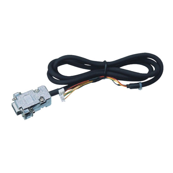
- Page 2 INTERFACE CABLE KCT-31 SERVICE MANUAL © 2000-2 PRINTED IN JAPAN B51-8573-00(S) 1433 CONTENTS OUTLINE ..............2 FEATURES ..............2 TERMINAL FUNCTION ..........2 INSTALLATION ............2 PARTS LIST ............... 3 SCHEMATIC DIAGRAM ..........3 PC BOARD VIEWS ............ 4...
- Page 3 INSTALLATION OUTLINE Note: When the COM 1 is used, A connector is unused. 1. The KCT-31 is a RS-232C interface cable for LMR Mobile When the COM 2 is used, C connector is unused. radios, TK-780,880,980,981 and TK-785,885. 1. Bind the unused connector to the cable with a retaining The 9-pin (D-sub) connector is connected to an external band as shown.
- Page 4 RK73GB1J473J CHIP R 1/16W Fig. 2 5. Insert the KCT-31 cable ( ) into the chassis ( ). The wire retaining band ( ) must be inside the chassis. 6. Replace the DC cable bushing ( ). SCHEMATIC DIAGRAM 7. Connect the KCT-31 to the TX-RX unit (A/2) as shown in figure 3 ( ).
- Page 5 Mechelsesteenweg 418 B-1930 Zaventem, Belgium KENWOOD ELECTRONICS FRANCE S.A. 13, Boulevard Ney, 75018 Paris, France KENWOOD ELECTRONICS U.K. LIMITED KENWOOD House, Dwight Road, Watford, Herts., WD1 8EB United Kingdom KENWOOD ELECTRONICS EUROPE B.V. Amsterdamseweg 37, 1422 AC Uithoorn, The Netherlands KENWOOD ELECTRONICS ITALIA S.p.A.
Need help?
Do you have a question about the KCT-31 and is the answer not in the manual?
Questions and answers