Advertisement
Ears
User manual
INSTALLATION
Ears requires a -12V / +12V power supply (2x5 pin connector). The ribbon cable connector must be aligned so that the red stripe of the ribbon
cable (-12V) is on the same side of the module's power header as the "Red stripe" marking on the board. The module draws 5mA from both the
+12V and the -12V supply rails.
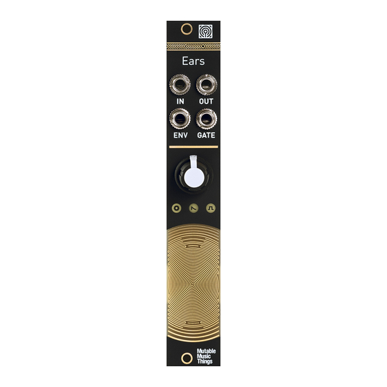
CONTROLS, INPUTS AND OUTPUTS
A. Gain control, 0 to +40dB. This large gain ranges covers everything - from the amplification of line-level instruments, to the magnification of
tiny sonic details captured by external contact microphones.
B. Contact microphone. Scratch, tap, rub, brush... to your heart's delight.
1. Hi-Z Audio input. Amplifies an external source. Patching a cable here disconnects the contact microphone.
2. Audio output. The red LED indicates clipping.
3. Envelope CV output. The white LED indicates the envelope CV level.
4. Gate output. Emits +8V when the envelope exceeds a threshold. The activity of this output is indicated by the orange LED.
ENVELOPE FOLLOWER AND GATE DETECTOR SETTINGS
The jumpers at the back of the module adjust the response of the envelope follower and gate detector.
The last setting, corresponding to the longest time or higher voltge, is obtained by removing the jumper.
WARRANTY
This product is covered by Mutable Instruments' warranty, for one year following the date of manufacture. This warranty covers any defect in the
manufacturing of this product. This warranty does not cover any damage or malfunction caused by incorrect use - such as, but not limited to,
power cables connected backwards, excessive voltage levels, or exposure to extreme temperature or moisture levels.
The warranty covers replacement or repair, as decided by Mutable Instruments. Please contact our customer service (support@mutable-
instruments.net) for a return authorization before sending the module. The cost of sending a module back for servicing is paid for by the
customer.
Mutable Instruments encourages modding and hacking, but we will not service modified units or provide any assistance in the realization of
mods.
Advertisement
Table of Contents

Subscribe to Our Youtube Channel
Related Manuals for Mutable Instruments Ears


Summary of Contents for Mutable Instruments Ears
- Page 1 INSTALLATION Ears requires a -12V / +12V power supply (2x5 pin connector). The ribbon cable connector must be aligned so that the red stripe of the ribbon cable (-12V) is on the same side of the module’s power header as the “Red stripe” marking on the board. The module draws 5mA from both the +12V and the -12V supply rails.
Need help?
Do you have a question about the Ears and is the answer not in the manual?
Questions and answers